
Airplane Flying Handbook
2021
U.S. Department of Transportation
FEDERAL AVIATION ADMINISTRATION
Flight Standards Service
i
Airplane Flying Handbook (FAA-H-8083-3C)
Preface
The Airplane Flying Handbook provides basic knowledge that is essential for pilots. This handbook introduces basic pilot
skills and knowledge that are essential for piloting airplanes. It provides information on transition to other airplanes and the
operation of various airplane systems. It is developed by the Flight Standards Service, Airman Testing Standards Branch,
in cooperation with various aviation educators and industry. This handbook is developed to assist student pilots learning
to fly airplanes. It is also beneficial to pilots who wish to improve their flying proficiency and aeronautical knowledge,
those pilots preparing for additional certificates or ratings, and flight instructors engaged in the instruction of both student
and certificated pilots. It introduces the future pilot to the realm of flight and provides information and guidance in the
performance of procedures and maneuvers required for pilot certification.
It is essential for persons using this handbook to become familiar with and apply the pertinent parts of 14 CFR and the
Aeronautical Information Manual (AIM). The AIM is available online at
www.faa.gov
. The current Flight Standards Service
airman training and testing material can be obtained from
www.faa.gov
.
This handbook supersedes FAA-H-8083-3B, Airplane Flying Handbook, dated 2016.
This handbook is available for download, in PDF format, from
www.faa.gov
.
This handbook is published by the United States Department of Transportation, Federal Aviation Administration, Airman
Testing Standards Branch, P.O. Box 25082, Oklahoma City, OK 73125.
Comments regarding this publication should be emailed to
AFS630comments@faa.gov
.
ii
iii
Airplane Flying Handbook (FAA-H-8083-3C)
Acknowledgments
The Airplane Flying Handbook was produced by the Federal Aviation Administration (FAA). The FAA wishes to
acknowledge the following contributors:
Mr. Shane Torgerson for imagery of the Sedona Airport (Chapter 1)
Mr. Robert Frola for imagery of an Evektor-Aerotechnik EV-97 SportStar Max (Chapter 16)
Additional appreciation is extended to the General Aviation Joint Steering Committee (GA JSC) and the Aviation Rulemaking
Advisory Committee’s (ARAC) Airman Certification Standards (ACS) Working Group for their technical support and input.
iv
Airplane Flying Handbook (FAA-H-8083-3C)
Major Revisions
•
Removed mandatory language or cited applicable regulations throughout handbook.
•
Chapter 1 (Introduction to Flight Training) – Added information on the FAA Wings Program.
•
Chapter 2 (Ground Operations) – Added a new graphic and information regarding detonation. Now uses
the same marshalling graphic as the AMT General Handbook. Updated material on hand propping to
match the material in the AMT General Handbook (it doesn’t matter whether a pilot or mechanic is hand
propping).
•
Chapter 3 (Basic Flight Maneuvers) – Corrected G1000 and indications of slip and skid graphics.
•
Chapter 4 (Energy Management) – All new chapter/material. Incremented the existing chapters 4-17 by 1
(now there are 18 chapters in total).
•
Chapter 5 (Maintaining Aircraft Control) – Revised the order in which the material was presented.
•
Chapter 7 (Ground Reference Maneuvers) – Corrected errors in text and graphics for eights on pylons.
•
Chapter 9 (Approaches and Landings) – Added information concerning a forward slip to a landing and
corrected Figure 9-6. Changed description associated with Crosswind Final Approach. Removed
material on 360 degree power-off landing as this maneuver is not part of testing standard.
•
Chapter 10 (Performance Maneuvers) – Added information on lazy eights.
•
Chapter 11 (Night Operations) – Revised to align with material from CAMI.
•
Chapter 13 (Transition to Multiengine Airplanes) – Incorporated the addendum. Corrected G1000
displays and force vectors on figures. Accelerated approach to stall minimum altitude revised to match
the ACS. The 14 CFR part 23 certification standard used for many multiengine airplanes is now referred
to a historical standard, since many of the previous requirements will not apply to newly certificated
aircraft.
•
Chapter 14 (Transition to Tailwheel Airplanes) – Made minor revision regarding handling characteristics.
•
Chapter 15 (Transition to Turboprop
eller-Powered Airplanes
) – Addressed an NTSB recommendation
regarding slow spool up time of split-shaft engines and corrected figure of fixed-shaft engine gauges.
•
Chapter 16 (Transition to
J
et
-Powered
Airplanes) – Removed extra information that appears unrelated to
flying a turbojet and added information regarding energy management and distance versus altitude in a
descent.
•
Chapter 18 (Emergency Procedures) – Revised information regarding the safety of turning back after an
engine failure after takeoff. Added a section on emergency response systems to include ballistic
parachutes and autoland systems. Corrected figures of G1000 displays.
v
vi
Airplane Flying Handbook (FAA-H-8083-3C)
Table of Contents
Chapter 1: Introduction to Flight Training
Introduction
1-1
Role of the FAA
1-2
Flight Standards Service
1-5
Role of the Pilot Examiner
1-6
Role of the Flight Instructor
1-6
Sources of Flight Training
1-8
Airman Certification Standards (ACS) and Practical Test Standards (PTS)
1-9
Safety Considerations
1-10
Collision Avoidance
1-10
Runway Incursion Avoidance
1-12
Stall Awareness
1-13
Use of Checklists
1-15
Continuing Education
1-16
FAA Wings Program
1-16
Chapter Summary
1-16
Chapter 2: Ground Operations
Introduction
2-1
Preflight Assessment of the Aircraft
2-1
Visual Preflight Assessment
2-4
Outer Wing Surfaces and Tail Section
2-6
Fuel and Oil
2-7
Landing Gear, Tires, and Brakes
2-10
Engine and Propeller
2-11
Risk and Resource Management
2-12
Risk Management
2-12
Identifying the Hazard
2-12
Risk
2-13
Risk Assessment
2-13
Risk Identification
2-13
Risk Mitigation
2-13
Resource Management
2-13
Situational Awareness
2-13
Human Resource Management
2-13
Task Management
2-14
Aeronautical Decision-Making (ADM)
2-14
Ground Operations
2-14
Engine Starting
2-16
Hand Propping
2-16
Taxiing
2-18
Before Takeoff Check
2-21
Takeoff Checks
2-22
After Landing
2-22
vii
Clear of Runway and Stopped
2-22
Parking
2-23
Engine Shutdown
2-23
Post-Flight
2-23
Securing and Servicing
2-23
Chapter Summary
2-24
Chapter 3: Basic Flight Maneuvers
Introduction
3-1
The Four Fundamentals
3-1
Effect and Use of Flight Controls
3-1
Feel of the Airplane
3-3
Attitude Flying
3-4
Integrated Flight Instruction
3-5
Straight-and-Level Flight
3-6
Straight Flight
3-6
Level Flight
3-8
Common Errors
3-8
Trim Control
3-10
Level Turns
3-11
Turn Radius
3-14
Establishing a Turn
3-15
Common Errors
3-17
Climbs and Climbing Turns
3-17
Establishing a Climb
3-19
Climbing Turns
3-20
Common Errors
3-20
Descents and Descending Turns
3-20
Glides
3-21
Gliding Turns
3-23
Common Errors
3-24
Chapter Summary
3-25
Chapter 4:
Energy Management: Mastering Altitude and Airspeed Control
Introduction
4-1
Importance of Energy Management
4-1
Viewing the Airplane as an Energy System
4-1
A Frame of Reference for Managing Energy State
4-1
Managing Energy is a Balancing Act
4-3
Role of the Controls to Manage Energy State
4-3
Primary Energy Role of the Throttle and Elevator
4-4
Additional Role for the Elevator
4-5
Rules of Energy Control
4-6
Visualizing the Airplane’s
Ability to “Move” Between Energy
States
4-7
Three Basic Rules of Energy Control
4-9
Mitigating Risks from Mismanagement of Energy
4-11
Two Energy Management Scenarios
4-11
Scenario 1
4-11
viii
Scenario 2
4-11
Managing Energy Errors
4-12
Preventing Irreversible Deceleration and/or Sink Rate
4-14
Review of Definitions and Terms
4-18
Chapter Summary
4-19
Chapter 5: Maintaining Aircraft Control: Upset Prevention and Recovery Training
Introduction
5-1
Defining an Airplane Upset
5-1
Upset Prevention and Recovery
5-1
Unusual Attitudes Versus Upsets
5-1
Environmental Factors
5-2
Mechanical Factors
5-2
Human Factors
5-2
IMC
5-2
Diversion of Attention
5-2
Task Saturation
5-3
Sensory Overload/Deprivation
5-3
Spatial Disorientation
5-3
Surprise and Startle Response
5-3
Upset Prevention and Recovery Training (UPRT)
5-4
UPRT Core Concepts
5-5
Academic Material (Knowledge and Risk Management
5-5
Prevention Through ADM and Risk Management
5-6
Prevention Through Proportional Counter-Response
5-6
Recovery
5-6
Common Errors
5-7
Roles of FSTDs and Airplanes in UPRT
5-7
Airplane-Based UPRT
5-7
All-Altitude/All Envelope Flight Training Methods
5-8
FSTD-Based UPRT
5-8
Coordinated Flight
5-8
Angle of Attack
5-8
Slow Flight
5-9
Performing the Slow Flight Maneuver
5-10
Maneuvering in Slow Flight
5-11
Common Errors
5-12
Stalls
5-12
Stall Recognition
5-13
Angle of Attack Indicators
5-13
Stall Characteristics
5-15
Fundamentals of Stall Recovery
5-15
Stall Training
5-16
Approaches to Stalls (Impending Stalls), Power-On or Power-Off
5-17
Full Stalls, Power-Off
5-17
Full Stalls, Power-On
5-18
Secondary Stall
5-18
ix
Accelerated Stalls
5-19
Cross-Control Stall
5-20
Elevator Trim Stall
5-20
Common Errors
5-21
Spin Awareness
5-22
Spin Procedures
5-23
Entry Phase
5-24
Incipient Phase
5-24
Developed Phase
5-24
Recovery Phase
5-24
Intentional Spins
5-25
Weight and Balance Requirements Related to Spins
5-26
Common Errors
5-26
Spiral Dive
5-26
Common Errors
5-27
UPRT Summary
5-27
Chapter Summary
5-27
Chapter 6: Takeoffs and Departure Climbs
Introduction
6-1
Terms and Definitions
6-1
Prior to Takeoff
6-1
Normal Takeoff
6-3
Takeoff Roll
6-3
Lift-Off
6-4
Initial Climb
6-5
Common Errors
6-6
Crosswind Takeoff
6-6
Takeoff Roll
6-6
Lift-Off
6-7
Initial Climb
6-8
Common Errors
6-10
Ground Effect on Takeoff
6-10
Short-Field Takeoff and Maximum Performance Climb
6-11
Takeoff Roll
6-11
Lift-Off
6-12
Initial Climb
6-12
Common Errors
6-12
Soft/Rough-Field Takeoff and Climb
6-13
Takeoff Roll
6-13
Lift-Off
6-13
Initial Climb
6-13
Common Errors
6-14
Rejected Takeoff/Engine Failure
6-14
Noise Abatement
6-14
Chapter Summary
6-14
x
Chapter 7: Ground Reference Maneuvers
Introduction
7-1
Maneuvering by Reference to Ground Objects
7-1
Drift and Ground Track Control
7-2
Correcting Drift During Straight and Level Flight
7-2
Constant Radius During Turning Flight
7-3
Tracking Over and Parallel to a Straight Line
7-5
Rectangular Course
7-5
Common Errors
7-7
Turns Around a Point
7-7
S-Turns
7-8
Common Errors
7-10
Elementary Eights
7-10
Eights along a Road
7-11
Eights across a Road
7-12
Eights around Pylons
7-13
Common Errors
7-13
Eights-on-Pylons
7-14
Common Errors
7-18
Chapter Summary
7-18
Chapter 8: Airport Traffic Patterns
Introduction
8-1
Airport Traffic Patterns and Operations
8-1
Standard Airport Traffic Patterns
8-1
Non-Towered Airports
8-4
Safety Considerations
8-5
Chapter Summary
8-7
Chapter 9: Approaches and Landings
Introduction
9-1
Use of Flaps
9-1
Normal Approach and Landing
9-2
Base Leg
9-2
Final Approach
9-3
Wrong Surface Landing Avoidance
9-4
Stabilized Approach Concept
9-4
Estimating Airplane Movement and Height
9-7
Round Out (Flare)
9-8
Touchdown
9-9
After-Landing Roll
9-9
Common Errors
9-10
Go-Arounds (Rejected Landings)
9-10
Power
9-11
Attitude
9-11
Configuration
9-11
Ground Effect
9-12
xi
Common Errors
9-12
Intentional Slips
9-12
Forward Slip to a Landing
9-15
Common Errors
9-15
Crosswind Approach and Landing
9-15
Crosswind Final Approach
9-15
Crosswind Round Out (Flare)
9-17
Crosswind Touchdown
9-17
Crosswind After-Landing Roll
9-18
Maximum Safe Crosswind Velocities
9-18
Common Errors
9-20
Turbulent Air Approach and Landing
9-20
Short-Field Approach and Landing
9-20
Common Errors
9-23
Soft-Field Approach and Landing
9-23
Common Errors
9-24
Power-Off Accuracy Approaches
9-24
90° Power-Off Approach
9-25
180° Power-Off Approach
9-26
Common Errors
9-27
Emergency Approaches and Landings (Simulated)
9-28
Faulty Approaches and Landings
9-30
Low Final Approach
9-30
High Final Approach
9-30
Slow Final Approach
9-31
Use of Power
9-31
High Round Out
9-31
Late or Rapid Round Out
9-31
Floating During Round Out
9-32
Ballooning During Round Out
9-32
Bouncing During Touchdown
9-33
Porpoising
9-34
Wheelbarrowing
9-35
Hard Landing
9-35
Touchdown in a Drift or Crab
9-35
Ground Loop
9-36
Wing Rising After Touchdown
9-37
Hydroplaning
9-37
Dynamic Hydroplaning
9-37
Reverted Rubber Hydroplaning
9-37
Viscous Hydroplaning
9-37
Chapter Summary
9-38
Chapter 10: Performance Maneuvers
Introduction
10-1
Steep Turns
10-1
Common Errors
10-3
xii
Steep Spiral
10-3
Common Errors
10-4
Chandelle
10-4
Common Errors
10-6
Lazy Eight
10-6
Common Errors
10-7
Chapter Summary
10-8
Chapter 11: Night Operations
Introduction
11-1
Night Vision
11-1
Anatomy of the Eye
11-1
Types of Vision
11-2
The Night Blind Spot
11-3
Vision Under Dim and Bright Illumination
11-3
Factors Affecting Vision
11-3
Night Illusions
11-4
False Horizon
11-4
Autokinesis
11-4
Featureless Terrain Illusion
11-5
Ground Lighting Illusions
11-5
Pilot Equipment
11-5
Airplane Equipment and Lighting
11-5
Airport and Navigation Lighting Aids
11-6
Training for Night Flight
11-7
Preparation and Preflight
11-7
Starting, Taxiing, and Run-up
11-8
Takeoff and Climb
11-8
Orientation and Navigation
11-9
Approaches and Landings
11-10
How to Prevent Landing Errors Due to Optical Illusions
11-13
Night Emergencies
11-13
Chapter Summary
11-14
Chapter 12: Transition to Complex Airplanes
Introduction
12-1
Function of Flaps
12-1
Flap Effectiveness
12-3
Operational Procedures
12-4
Controllable-Pitch Propeller
12-5
Constant-Speed Propeller
12-5
Takeoff, Climb, and Cruise
12-6
Blade Angle Control
12-7
Governing Range
12-8
Constant-Speed Propeller Operation
12-8
Turbocharging
12-9
Ground Boosting Versus Altitude Turbocharging
12-10
Operating Characteristics
12-10
xiii
Heat Management
12-10
Turbocharger Failure
12-11
Over-Boost Condition
12-11
Low Manifold Pressure
12-11
Retractable Landing Gear
12-12
Landing Gear Systems
12-12
Controls and Position Indicators
12-12
Landing Gear Safety Devices
12-12
Emergency Gear Extension Systems
12-14
Operational Procedures
12-14
Takeoff and Climb
12-16
Approach and Landing
12-16
Transition Training
12-17
Chapter Summary
12-18
Chapter 13: Transition to Multiengine Airplanes
Introduction
13-1
General
13-1
Terms and Definitions
13-1
Operation of Systems
13-3
Feathering Propellers
13-3
Propeller Synchronization
13-7
Fuel Crossfeed
13-7
Combustion Heater
13-8
Flight Director/Autopilot
13-8
Yaw Damper
13-8
Alternator/Generator
13-9
Nose Baggage Compartment
13-9
Anti-Icing/Deicing Equipment
13-9
Performance and Limitations
13-10
Weight and Balance
13-12
Ground Operation
13-14
Normal and Crosswind Takeoff and Climb
13-15
Short-Field Takeoff and Climb
13-17
Rejected Takeoff
13-17
Level Off and Cruise
13-17
Slow Flight
13-18
Spin Awareness and Stalls
13-18
Spin Awareness
13-18
Stall Training
13-18
Power-Off Approach to Stall (Approach and Landing)
13-19
Power-On Approach to Stall (Takeoff and Departure)
13-19
Full Stall
13-20
Accelerated Approach to Stall
13-20
Normal Approach and Landing
13-20
Crosswind Approach and Landing
13-21
Short-Field Approach and Landing
13-22
xiv
Go-Around
13-22
Engine Inoperative Flight Principles
13-23
Derivation of V
MC
13-23
V
MC
Demo
13-26
V
MC
Demo Stall Avoidance
13-26
OEI Climb Performance
13-27
Low Altitude Engine Failure Scenarios
13-29
Landing Gear Down
13-30
Landing Gear Control Selected Up, Single-Engine Climb Performance Inadequate
13-30
Landing Gear Control Selected Up, Single-Engine Climb Performance Adequate
13-31
Control
13-31
Configuration
13-31
Climb
13-32
Checklist
13-32
Engine Failure During Flight
13-34
Engine Inoperative Approach and Landing
13-34
Multiengine Training Considerations
13-35
Chapter Summary
13-37
Chapter 14: Transition to Tailwheel Airplanes
Introduction
14-1
Landing Gear
14-1
Instability
14-1
Angle of Attack
14-2
Taxiing
14-2
Weathervaning
14-2
Visibility
14-3
Directional Control
14-3
Normal Takeoff Roll
14-3
Liftoff
14-3
Crosswind Takeoff
14-3
Short-Field Takeoff
14-4
Soft-Field Takeoff
14-4
Landing
14-4
Touchdown
14-4
Three-Point Landing
14-5
Wheel Landing
14-5
Crosswinds
14-6
After-Landing Roll
14-6
Crosswind After-Landing Roll
14-7
Short-Field Landing
14-8
Soft-Field Landing
14-8
Ground Loop
14-8
Chapter Summary
14-8
Chapter 15: Transition to Turbopropeller-Powered Airplanes
Introduction
15-1
Gas Turbine Engine
15-1
xv
15-2
Turboprop Engines
Fixed-Shaft
15-2
Split-Shaft/Free Turbine Engine
15-5
Reverse Thrust and Beta Range Operations
15-8
Turboprop Airplane Electrical Systems
15-10
Operational Considerations
15-11
Training Considerations
15-13
Ground Training
15-14
Flight Training
15-15
Chapter Summary
15-15
Chapter 16: Transition to Jet-Powered Airplanes
Introduction
16-1
Ground Safety
16-1
Jet Engine Basics
16-1
Operating the Jet Engine
16-2
Setting Power
16-2
Thrust to Thrust Lever Relationship
16-2
Variation of Thrust with RPM
16-3
Slow Acceleration of the Jet Engine
16-3
Jet Engine Efficiency
16-4
Absence of Propeller Effects
16-4
Absence of Propeller Slipstream
16-4
Absence of Propeller Drag
16-4
Speed Margins
16-4
Mach Buffet
16-6
Low-Speed Flight
16-6
Stalls
16-7
Drag Devices
16-9
Thrust Reversers
16-10
Pilot Sensations in Jet Flying
16-11
Jet Airplane Takeoff and Climb
16-12
V-Speeds
16-12
Takeoff Roll
16-12
Rejected Takeoff
16-15
Rotation and Lift-Off
16-16
Initial Climb
16-16
Jet Airplane Descent and Approach
16-17
Descent Planning
16-17
Descent Energy Management
16-18
Jet Airplane Landing
16-19
Landing Speeds
16-20
Significant Differences
16-21
Stabilized Approach
16-21
Approach Speed
16-22
Glidepath Control
16-22
The Flare
16-23
xvi
16-24
Touchdown and Rollout
Jet Airplane Systems and Maintenance
16-24
Minimum Equipment List
16-25
Configuration Deviation List
16-25
Chapter Summary
16-25
Chapter 17: Transition to Light Sport Airplanes (LSA)
Introduction
17-1
Light Sport Airplane (LSA) Background
17-1
LSA Synopsis
17-3
Sport Pilot Certificate
17-3
Transition Training Considerations
17-4
Flight School
17-4
Flight Instructors
17-4
LSA Maintenance
17-5
Airframe and Systems
17-5
Construction
17-5
Engines
17-6
Instrumentation
17-7
Weather Considerations
17-7
Flight Environment
17-8
Preflight
17-9
Inside the Airplane
17-9
Outside the Airplane
17-11
Before Start and Starting Engine
17-12
Taxi
17-12
Takeoff and Climb
17-12
Cruise
17-13
Approach and Landing
17-14
Emergencies
17-14
Post-Flight
17-15
Key Points
17-15
Chapter Summary
17-15
Chapter 18: Emergency Procedures
Emergency Situations
18-1
Emergency Landings
18-1
Types of Emergency Landings
18-1
Psychological Hazards
18-1
Basic Safety Concepts
18-2
General
18-2
Attitude and Sink Rate Control
18-4
Terrain Selection
18-4
Airplane Configuration
18-4
Approach
18-4
Terrain Types
18-5
Confined Areas
18-5
Trees (Forest)
18-5
xvii
Water (Ditching) and Snow
Engine Failure After Takeoff (Single-Engine)
Emergency Descents
In-Flight Fire
Engine Fire
Electrical Fires
Cabin Fire
Flight Control Malfunction/Failure
Total Flap Failure
Asymmetric (Split) Flap
Loss of Elevator Control
Landing Gear Malfunction
System Malfunctions
Electrical System
Pitot-Static System
Abnormal Engine Instrument Indication
Door Opening In-Flight
Inadvertent VFR Flight Into IMC
Recognition
Maintaining Airplane Control
Attitude Control
Turns
Climbs
Descents
Combined Maneuvers
Transition to Visual Flight
Emergency Response Systems
Ballistic Parachute
Autoland
Chapter Summary
Glossary
Index
18-7
18-7
18-8
18-9
18-9
18-10
18-10
18-10
18-10
18-11
18-11
18-12
18-13
18-13
18-14
18-16
18-17
18-17
18-17
18-18
18-18
18-19
18-20
18-20
18-21
18-22
18-22
18-22
18-22
18-23
G-1
I-1
xviii
Airplane Flying Handbook (FAA-H-8083-3C)
Chapter 1: Introduction to Flight Training
Introduction
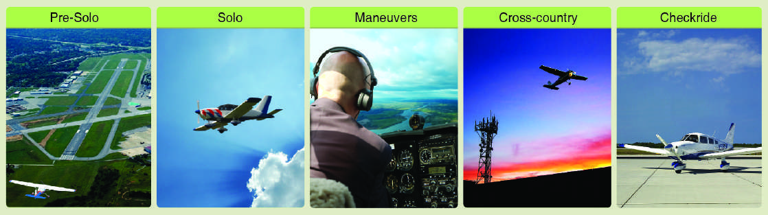
The overall purpose of primary and intermediate flight training, as outlined in this handbook, is the acquisition and honing of basic
airmanship skills.
[Figure 1-1]
Airmanship is a broad term that includes a sound knowledge of and experience with the principles of
flight; the knowledge, experience, and ability to operate an aircraft with competence and precision both on the ground and in the air;
and the application of sound judgment that results in optimal operational safety and efficiency.
[Figure 1-2]
Learning to fly an
aircraft has often been compared to learning to drive an automobile. This analogy is misleading. Since aircraft operate in a three-
dimensional environment, they require a depth of knowledge and type of motor skill development that is more sensitive to this
situation, such as:
⦁
Coordination
–
the ability to use the hands and feet together subconsciously and in the proper relationship
to produce desired results in the airplane.
⦁
Timing
–
the application of muscular coordination at the proper instant to make flight, and all maneuvers, a
constant, smooth process.
⦁
Control touch
–
the ability to sense the action of the airplane and knowledge to determine its probable
actions immediately regarding attitude and speed variations by sensing the varying pressures and resistance
of the control surfaces transmitted through the flight controls.
⦁
Speed sense
–
the ability to sense and react to reasonable variations of airspeed.
Figure 1-1.
Primary and intermediate flight training teaches basic airmanship skills and creates a good foundation for learners.
An accomplished pilot demonstrates the knowledge and ability to:
⦁
Assess a situation quickly and accurately and determine the correct procedure to be followed under the
existing circumstance.
⦁
Predict the probable results of a given set of circumstances or of a proposed procedure.
⦁
Exercise care and due regard for safety.
⦁
Accurately gauge the performance of the aircraft.
⦁
Recognize personal limitations and limitations of the aircraft and avoid exceeding them.
⦁
Identify, assess, and mitigate risk on an ongoing basis.
1-1
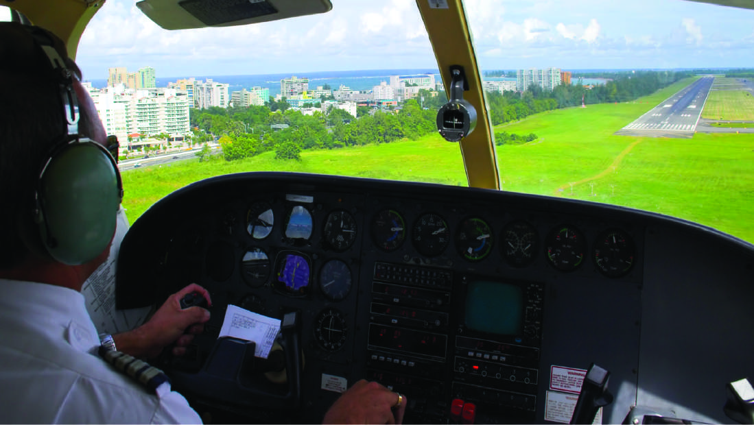
Figure 1-2.
Good airmanship skills include sound knowledge of the principles of flight and the ability to operate an airplane with
competence and precision.
The development of airmanship skills depends upon effort and dedication on the part of both the learner and the flight instructor,
beginning with the very first training flight where proper habit formation begins with the learner being introduced to good operating
practices.
Every airplane has its own particular flight characteristics. The purpose of primary and intermediate flight training, however, is not to
learn how to fly a particular make and model airplane. The purpose of flight training is to develop the knowledge, experience, skills,
and safe habits that establish a foundation and are transferable to any airplane. The pilot who has acquired necessary skills during
training, and develops these skills by flying training-type airplanes with precision and safe flying habits, is able to easily transition to
more complex and higher performance airplanes. Also note that the goal of flight training is a safe and competent pilot; passing
required practical tests for pilot certification is only incidental to this goal.
Role of the FAA
The Federal Aviation Administration (FAA) is empowered by the U.S. Congress to promote aviation safety by prescribing safety
standards for civil aviation. Standards are established for the certification of airmen and aircraft, as well as outlining operating rules.
This is accomplished through the Code of Federal Regulations (CFR), formerly referred to as Federal Aviation Regulations (FAR).
Title 14 of the CFR (14 CFR) is titled Aeronautics and Space with Chapter 1 dedicated to the FAA. Subchapters are broken down by
category with numbered parts detailing specific information.
[Figure 1-3]
For ease of reference and since the parts are numerical, the
abbreviated pattern 14 CFR part ___ is used (e.g., 14 CFR part 91).
This guidance is not legally binding in its own right and will not be relied upon by the FAA as a separate basis for affirmative
enforcement action or other administrative penalty. Conformity with the guidance is voluntary only and nonconformity will not affect
rights and obligations under existing statutes and regulations.
While the various subchapters and parts of 14 CFR provide general to specific guidance regarding aviation operations within the
U.S., the topic of aircraft certification and airworthiness is spread through several interconnected parts of 14 CFR.
1-2
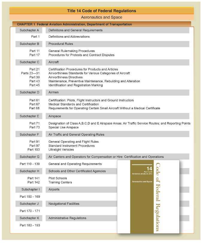
Figure 1-3.
Title 14 CFR, Chapter 1, Aeronautics and Space and subchapters.
⦁
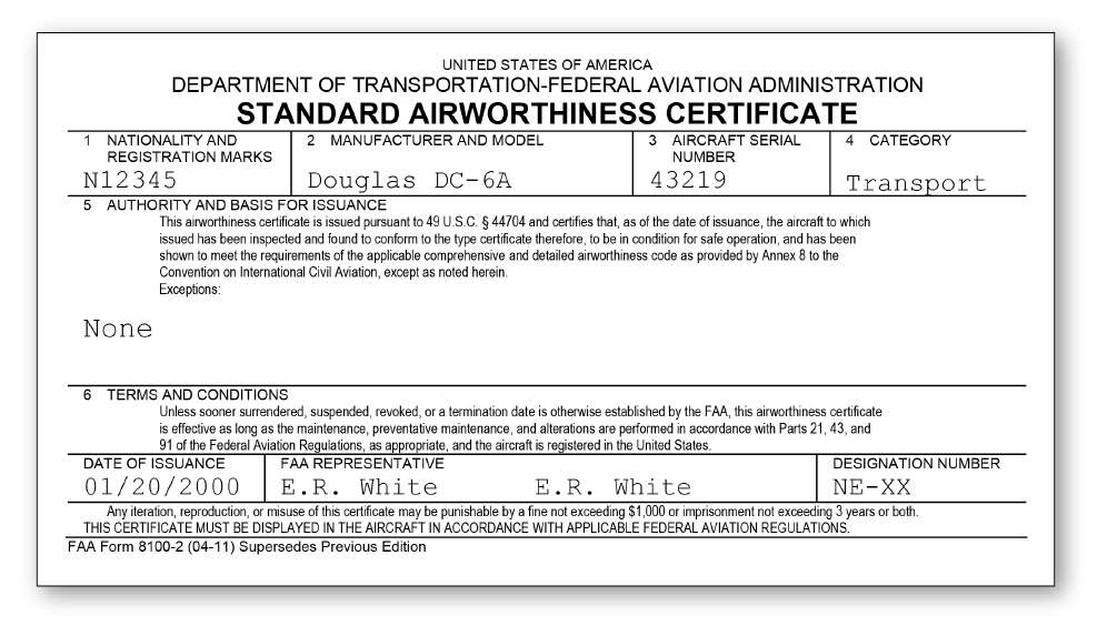
14 CFR part 21 prescribes procedural requirements for issuing airworthiness certificates and
airworthiness approvals for aircraft and aircraft parts. A standard airworthiness certificate, FAA Form
8100-2
[Figure 1-4]
, is required to be displayed in the aircraft in accordance with 14 CFR part 91,
section 91.203(b). It is issued for aircraft type certificated in the normal, utility, acrobatic, commuter or
transport category, and for manned free balloons. A standard airworthiness certificate remains valid as long
as the aircraft meets its approved type design, is in a condition for safe operation and maintenance, and
preventative maintenance and alterations are performed in accordance with 14 CFR parts 21, 43, and 91.
⦁
14 CFR part 39 is the authority for the FAA to issue Airworthiness Directives (ADs) when an unsafe
condition exists in a product, aircraft, or part, and the condition is likely to exist or develop in other
products of the same type design.
⦁
14 CFR part
43 prescribes rules governing the maintenance, preventive maintenance, rebuilding, and
alteration of any aircraft having a U.S. airworthiness certificate. It also applies to the airframe,
aircraft engines, propellers, appliances, and component parts of such aircraft.
⦁
14 CFR part
45 identifies the requirements for the identification of aircraft, engines, propellers, certain
replacement and modification parts, and the nationality and registration marking required on U.S.-
registered aircraft.
1-3
⦁
14 CFR part 91 outlines aircraft certifications and equipment requirements for the operation of aircraft in
U.S. airspace. It also prescribes rules governing maintenance, preventive maintenance, and alterations. Also
found in 14 CFR part 91 is the requirement to maintain records of maintenance, preventive maintenance,
and alterations, as well as records of the 100-hour, annual, progressive, and other required or approved
inspections.
Figure 1-4.
FAA Form 8100-2, Standard Airworthiness Certificate.
While 14
CFR
part 91,
section
91.205
outlines the minimum
equipment required
for
flight, the Airplane Flight Manual/Pilot’s
Operating Handbook (AFM/POH) lists the equipment required for the airplane to be airworthy. The equipment list found in the
AFM/POH is developed during the airplane certification process. This list identifies those items that are required for airworthiness,
optional equipment installed in addition to the required equipment, and any supplemental items or appliances.
Figure 1-5
shows an example of some of the required equipment, standard or supplemental (not required but commonly found in the
aircraft) and optional equipment for an aircraft. The equipment list, originally issued by the manufacturer, is maintained by the Type
Certificate Data Sheet (TCDS). An aircraft and its installed components and parts must conform to the original Type Certificate or
approved altered conditions to meet the definition of airworthy in accordance with 14 CFR part 3.5.
Certification requirements for pilots, medical certificate requirements, and operating rules are found in the following parts:
⦁
14 CFR part 61 pertains to the certification of pilots, flight instructors, and ground instructors. It
prescribes the eligibility, aeronautical knowledge, flight proficiency training, and testing requirements for
each type of pilot certificate issued.
⦁
14 CFR part 67 prescribes the medical standards and certification procedures for issuing medical
certificates for airmen and for remaining eligible for a medical certificate.
⦁
14 CFR part 68 contains requirements for operating certain small aircraft without a medical certificate.
⦁
14 CFR part 91 contains general operating and flight rules. The section is broad in scope and
provides general guidance in the areas of general flight rules, visual flight rules (VFR), instrument
flight rules (IFR), and as previously discussed aircraft maintenance, and preventive maintenance and
alterations.
1-4
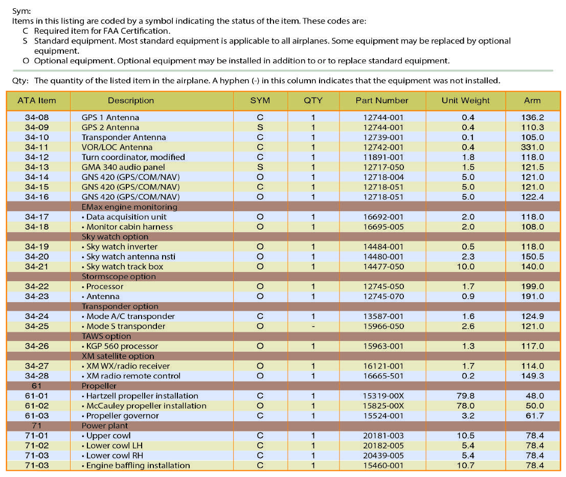
Figure 1-5.
Example of some of the required standard or supplemental and optional equipment for an aircraft.
Flight Standards Service
The
FAA’s
Flight
Standards
Service
(FS)
sets
aviation
standards
for
airmen
and
aircraft
operations
in
the
United
States
and
for
American airmen and aircraft around the world. Flight Standards is organized into four functional offices: Office of Safety Standards,
Air Carrier Safety Assurance, General Aviation Safety Assurance, and Foundational Business.
The primary interface between FS and the general aviation community/general public is the local Flight Standards District Office
(FSDO). The FSDOs are responsible for the certification and surveillance of certain air carriers, air operators, flight schools/training
centers, airmen (pilots, flight instructors, mechanics and other certificate holders). FSDO inspectors also handle general aviation
accident investigation at the request of, or in cooperation with, the National Transportation Safety Board.
Each FSDO is staffed by Aviation Safety Inspectors (ASIs) whose specialties include operations, maintenance, and avionics. General
Aviation ASIs are highly qualified and experienced aviators. Once accepted for the position, an inspector will satisfactorily complete
indoctrination training conducted at the FAA Academy. The indoctrination training coursework for a General Aviation Operations
Inspector, which is oriented to the tasks to be performed by an ASI in the general aviation environment, includes classroom and flight
training on pilot certification activities. Thereafter, the inspector will complete recurrent training on a regular basis. Among other
duties, the ASI is responsible for administering FAA practical tests for pilot and flight instructor certificates and associated ratings.
Questions concerning pilot certification and/or requests for other aviation information or services should be directed to the FSDO.
For specific FSDO locations and telephone numbers, refer to
www.faa.gov
.
1-5
Role of the Pilot Examiner
Pilot and flight instructor certificates are issued by the FAA upon satisfactory completion of required knowledge and practical tests.
The administration of practical tests is an FAA responsibility that may occur at the FSDO level. However, in order to satisfy the
public need for pilot testing and certification services, the FAA delegates certain responsibilities, as the need arises, to private
individuals who are not FAA employees. A Designated Pilot Examiner (DPE) is a private citizen who is designated as a
representative of the FAA Administrator to perform specific (but limited) pilot certification tasks on behalf of the FAA and may
charge a reasonable fee
for
doing
so.
Generally,
a DPE’s
authority
is
limited
to
accepting
applications
and
conducting
practical tests
leading to the issuance of specific pilot certificates and/or ratings. A DPE operates under the direct supervision of the FSDO that
holds
the examiner’s
designation
file.
A
FSDO inspector
is
assigned
to
monitor
the DPE’s
certification
activities.
The FAA selects highly qualified individuals to be DPEs. These individuals have good industry reputations for professionalism, high
integrity, a demonstrated willingness to serve the public, and adhere to FAA policies and procedures in certification matters. A DPE
is expected to administer practical tests with the same degree of professionalism, using the same methods, procedures, and standards
as an FAA ASI. Note that a DPE is not an FAA ASI. A DPE cannot initiate enforcement action, investigate accidents, or perform
surveillance activities on behalf of the FAA. However, the majority of FAA practical tests at the recreational, private, and commercial
pilot level are administered by DPEs.
Role of the Flight Instructor
The flight instructor is the cornerstone of aviation safety. The FAA has adopted an operational training concept that places the full
responsibility for pilot training on the flight instructor. In this role, the instructor assumes the total responsibility for providing
training in all the knowledge areas and skills necessary for pilots to operate safely and competently in the National Airspace System
(NAS). This training includes airmanship skills, pilot judgment and decision-making, hazard identification, risk analysis, and good
operating practices. (See Risk Management Handbook, FAA-H-8083-2).
[Figure 1-6]
Figure 1-6.
The flight instructor is responsible for teaching and training.
A flight instructor normally meets broad flying experience requirements, passes rigid knowledge and practical tests, and demonstrates
the ability to apply recommended teaching techniques before being certificated.
A pilot training program is dependent on the quality of the ground and flight instruction given. A good flight instructor has a
thorough understanding of the learning process, knowledge of the fundamentals of instruction, and the ability to communicate
effectively with the learner.
1-6
A good flight instructor uses a syllabus and insists on correct techniques and procedures from the beginning of training so that the
learner
will develop
proper
habit patterns.
The syllabus
should
embody
the “building
block” method
of
instruction
in
which
the
learner systematically progresses from the known to the unknown. The course of instruction should be laid out so that each new
maneuver embodies the principles involved in the performance of those previously undertaken. Consequently, through each new
subject introduced, the learner not only learns a new principle or technique, but also broadens their application of those previously
learned and has their deficiencies in the previous maneuvers emphasized and made obvious.
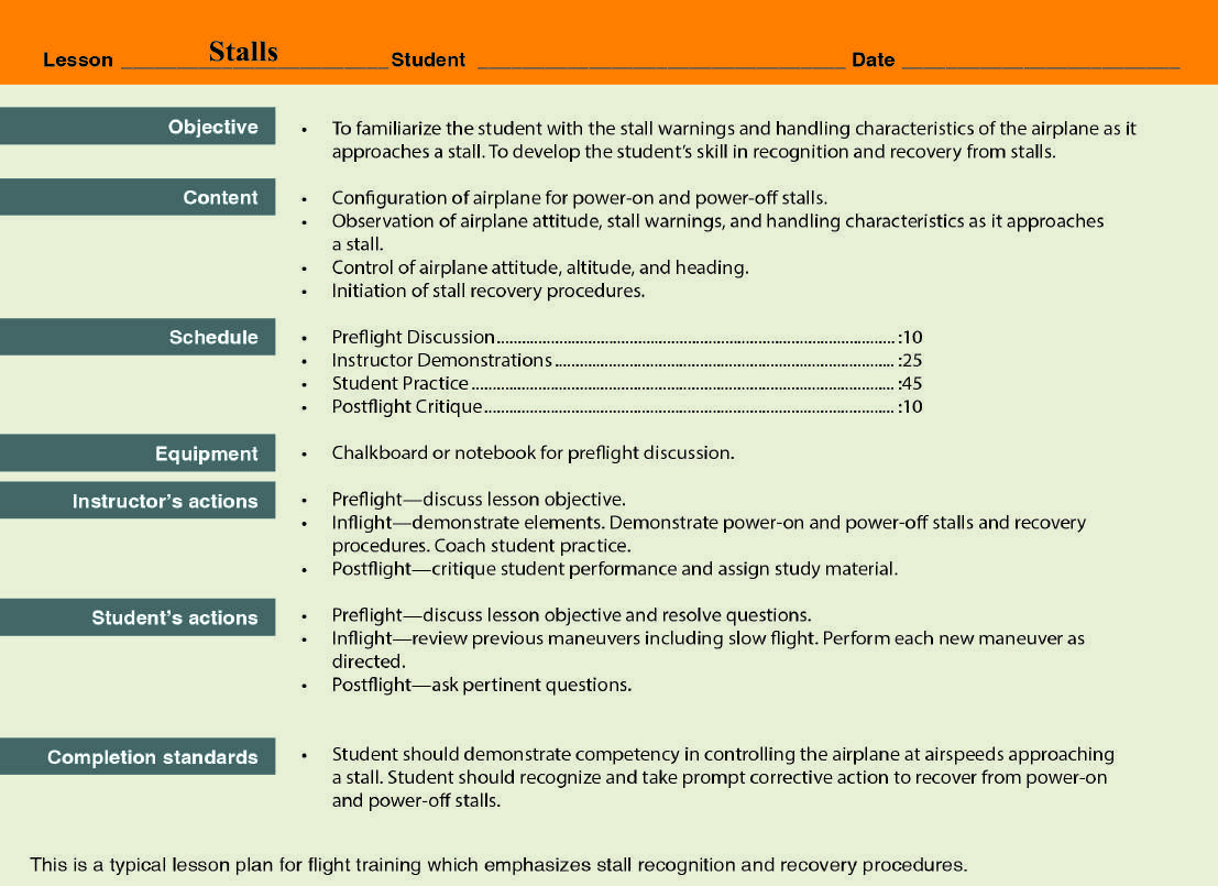
[Figure 1-7]
Figure 1-7.
Sample lesson plan for stall training and recovery procedures.
The flying habits of the flight instructor, both during flight instruction and as observed by learners when conducting other pilot
operations, have a vital effect on safety. Learners consider their flight instructor to be a paragon of flying proficiency whose flying
habits they, consciously or unconsciously, attempt to imitate. For this reason, a good flight instructor meticulously observes the safety
practices taught to the learners. Additionally, a good flight instructor carefully observes all regulations and recognized safety
practices during all flight operations.
A prospective pilot should know that there are other differences among flight instructors. Certain instructors who have performed at a
high level have earned a Gold Seal Flight Instructor Certificate. This is not a requirement when looking for an instructor, but it is
indication of an active and successful instructor. Top notch instructors also participate in the Pilot Proficiency Awards Wings
Program (Wings program) to improve their proficiency and to serve as an example to learners who also benefit from program
participation.
Generally, an individual who enrolls in a pilot training program is prepared to commit considerable time, effort, and expense in
pursuit of a pilot certificate. A trainee may judge the effectiveness of the flight instructor and the overall success of the pilot training
program solely in terms of being able to pass the requisite FAA practical test. A good flight instructor is able to communicate that
evaluation through practical tests is a mere sampling of pilot ability that is compressed into a short period of time. The flight
instructor’s
role is
to
train
the “total” pilot.
1-7
Sources of Flight Training
The major sources of flight training in the United States include FAA-approved pilot schools and training centers, non-certificated
(14 CFR part 61) flying schools, and independent flight instructors. FAA-approved schools are those flight schools certificated by the
FAA as pilot schools under 14 CFR part 141.
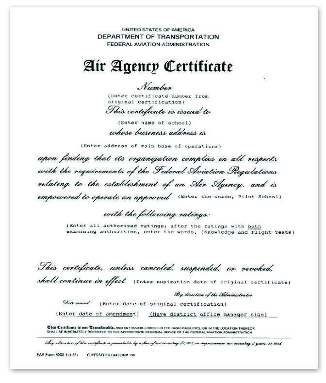
[Figure 1-8]
Figure 1-8.
FAA Form 8000-4, Air Agency Certificate.
Application for part 141 certification is voluntary, and the school needs to meet specific requirements for personnel, equipment,
maintenance, and facilities. The school operates each course offering in accordance with an established curriculum that includes a
training course outline (TCO) approved by the FAA. Each TCO contains enrollment prerequisites, a detailed description of each
lesson including standards and objectives, expected accomplishments and standards for each stage of training, and a description of the
checks and tests used to measure each training course enrollee's accomplishments. An FAA-approved pilot school Air Agency
certificate expires and needs to be renewed every 2 years.
Renewal is contingent upon proof of continued high quality instruction and a minimum level of instructional activity. Training at an
FAA-certificated pilot school is structured and because of this structured environment, the graduates of these pilot schools are
allowed to meet the certification experience requirements of 14 CFR part 61 with less flight time. Many FAA-certificated pilot
schools have DPEs on staff to administer FAA practical tests. Some schools have been granted examining authority by the FAA. A
school with examining authority for a particular course(s) has the authority to recommend its graduates for pilot certificates or ratings
without further testing by the FAA. A list of FAA-certificated pilot schools and their training courses can be found at
https://av-info.faa.gov/pilotschool.asp
.
FAA-approved training centers are certificated under 14 CFR part 142. Training centers, like certificated pilot schools, operate in a
structured environment with approved courses and curricula and stringent standards for personnel, equipment, facilities, operating
procedures, and record keeping. Training centers certificated under 14 CFR part 142, however, specialize in the use of flight
simulation (full flight simulators and flight training devices) in their training courses.
1-8
There are a number of flying schools in the United States that are not certificated by the FAA. These schools operate under the
provisions of 14 CFR part 61. Many of these non-certificated flying schools offer excellent training and meet or exceed the standards
required of FAA-approved pilot schools. Flight instructors employed by non-certificated flying schools, as well as independent flight
instructors, meet the same basic 14 CFR part 61 flight instructor requirements for certification and renewal as those flight instructors
employed by FAA-certificated pilot schools. In the end, any training program is dependent upon the quality of the ground and flight
instruction a learner receives.
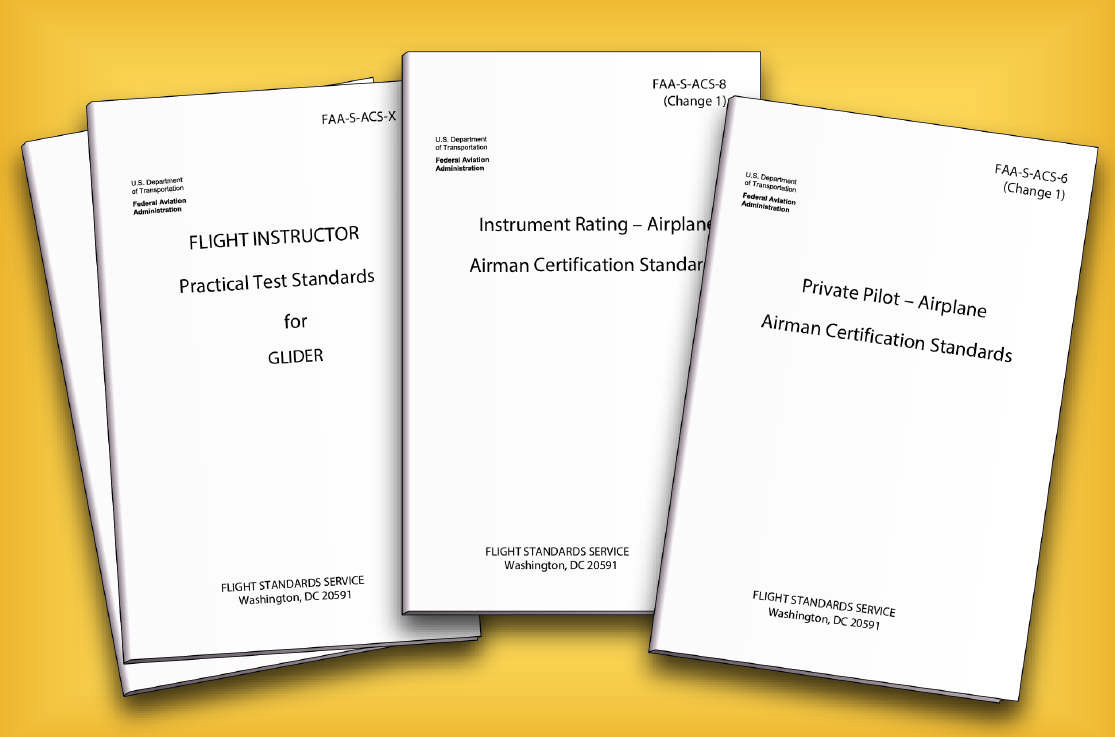
Airman Certification Standards (ACS) and Practical Test Standards (PTS)
Figure 1-9.
Airman Certification Standards (ACS) developed by FAA
Practical tests for FAA pilot certificates and associated ratings are administered by FAA inspectors and DPEs using FAA
Airman Certification Standards (ACS) and Practical Test Standards (PTS), which co
n
tain structured areas of operation, tasks, and
standards.
[Figure 1-9]
14 CFR part 61, section 61.43 specifies that the practical test consists of the tasks specif
i
ed in the areas of
operation for the airman certificate or rating sought
. To pass the test, the applicant
demonstrat
es
mastery of the aircraft
performing each task successfully,
pr
oficiency and competency within the approved standards, and sound judgment.
It should be emphasized that the ACS and PTS are testing documents rather than teaching documents. Although the pilot applicant
should be familiar with these books and refer to the standards they contain during training, the ACS and PTS are not intended to be
used as a training syllabus. They contain the standards to which maneuvers/procedures on FAA practical tests should be performed
and the FAA policies governing the administration of practical tests. An appropriately rated flight instructor is responsible for training
a pilot applicant to acceptable standards in all subject matter areas, procedures, and maneuvers included in, and encompassed by, the
tasks within each area of operation in the appropriate ACS and PTS. Flight instructors and pilot applicants should always remember
that safe, competent piloting requires a commitment to learning, planning, and risk management that goes beyond rote performance of
maneuvers. Descriptions of tasks and information on how to perform maneuvers and procedures are contained in reference and
teaching documents, such as this handbook. A list of reference documents is contained in the appendices of each ACS and PTS. It is
necessary that the latest version of the PTS and ACS, with all recent changes, be referenced for training. All recent versions and
changes to the FAA ACS and PTS may be viewed or downloaded at
www.faa.gov
.
1-9
Safety
Considerations
In the interest of safety and good habit pattern formation, there are certain basic flight safety practices and procedures that should be
emphasized by the flight instructor, and adhered to by both instructor and learner, beginning with the very first dual instruction flight.
These include, but are not limited to, collision avoidance procedures including proper scanning techniques and clearing procedures,
runway incursion avoidance, stall awareness, positive transfer of controls, and flight deck workload management.
Collision Avoidance
All pilots should be alert to the potential for midair collision and impending loss of separation. The general operating and flight rules
in
14
CFR
part
91
set
forth
the
concept
of
“see
and
avoid.”
This
concept
requires
that
vigilance
shall
be
maintained
at all times by
each person operating an aircraft regardless of whether the operation is conducted under IFR or VFR. Pilots should also keep in mind
their responsibility for continuously maintaining a vigilant lookout regardless of the type of aircraft being flown and the purpose of
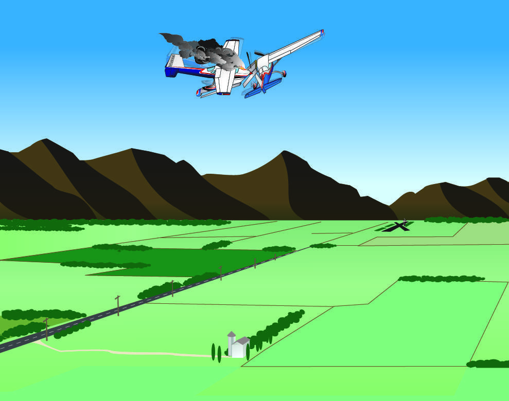
the flight. Most midair collision accidents and reported near midair collision incidents occur in good VFR weather conditions and
during the hours of daylight. Most of these accident/incidents occur within 5 miles of an airport and/or near navigation aids.
[Figure
1-10]
Figure 1-10.
Most midair collision accidents occur in good weather.
The “see
and
avoid” concept relies on
knowledge of
the limitations
of
the human
eye and
the use of
proper
visual scanning
techniques
to help compensate for these limitations. Pilots should remain constantly alert to all traffic movement within their field of vision, as
well as periodically scanning the entire visual field outside of their aircraft to ensure detection of conflicting traffic. Remember that
the performance capabilities of many aircraft, in both speed and rates of climb/descent, result in high closure rates limiting the time
available for detection, decision, and evasive action.
[Figure 1-11]
1-10
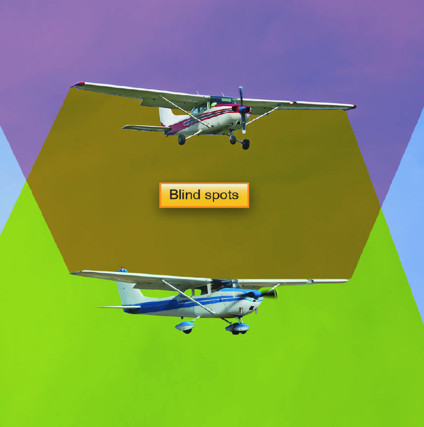
Figure 1-11.
Proper scanning techniques can mitigate midair collisions. Pilots should be aware of potential blind spots and attempt to
clear the entire area in which they are maneuvering.
The probability of spotting a potential collision threat increases with the time spent looking outside, but certain techniques may be
used to increase the effectiveness of the scan time. The human eyes tend to focus somewhere, even in a featureless sky. In order to be
most effective, the pilot should shift glances and refocus at intervals. Most pilots do this in the process of scanning the instrument
panel, but it is also important to focus outside to set up the visual system for effective target acquisition. Pilots should also realize that
their eyes may require several seconds to refocus when switching views between items on the instrument panel and distant objects.
Proper scanning requires the constant sharing of attention with other piloting tasks, thus it is easily degraded by psychological and
physiological conditions such as fatigue, boredom, illness, anxiety, or preoccupation.
Effective scanning is accomplished with a series of short, regularly-spaced eye movements that bring successive areas of the sky into
the central visual field. Each movement should not exceed 10 degrees, and each area should be observed for at least 1 second to
enable detection. Although horizontal back-and-forth eye movements seem preferred by most pilots, each pilot should develop a
scanning pattern that is comfortable and adhere to it to assure optimum scanning.
Peripheral vision can be most useful in spotting collision threats from other aircraft. Each time a scan is stopped and the eyes are
refocused, the peripheral vision takes on more importance because it is through this element that movement is detected. Apparent
movement is usually the first perception of a collision threat and probably the most important because it is the discovery of a threat
that triggers the events leading to proper evasive action. It is essential to remember that if another aircraft appears to have no relative
motion, it is likely to be on a collision course. If the other aircraft shows no lateral or vertical motion, but is increasing in size, the
observing pilot needs to take immediate evasive action to avoid a collision.
1-11
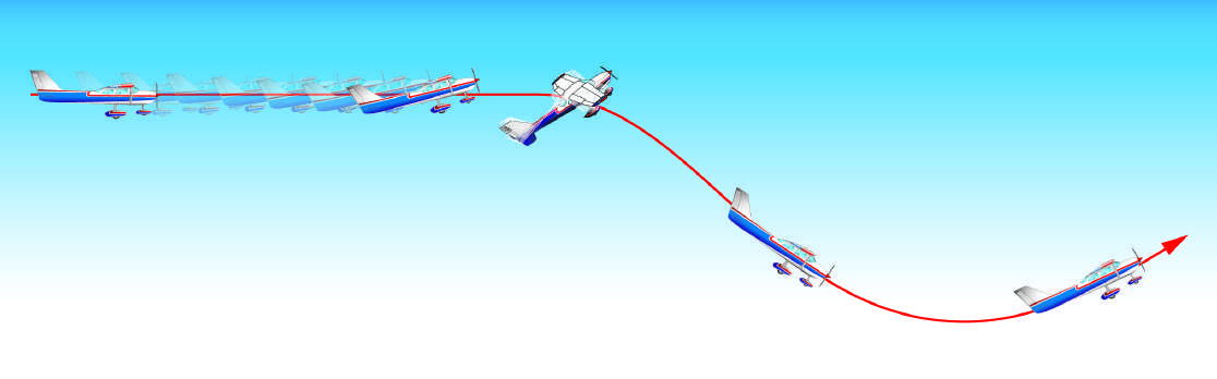
The importance of, and the proper techniques for, visual scanning should be taught at the very beginning of flight training. The
competent flight instructor should be familiar with the visual scanning and collision avoidance information contained in AC 90-48,
Pilots’
Role in
Collision
Avoidance
, and the Aeronautical Information Manual (AIM).
There are many different types of clearing procedures. Most are centered around the use of clearing turns. The essential idea of the
clearing
turn
is
to
be certain
that the next maneuver
is
not going
to
proceed
into
another
aircraft’s
flightpath.
Some pilot training
programs have hard and fast rules, such as requiring two 90° turns in opposite directions before executing any training maneuver.
Other types of clearing procedures may be developed by individual flight instructors. Whatever the preferred method, the flight
instructor should teach the beginning learner an effective clearing procedure and insist on its use. The learner should execute the
appropriate clearing procedure before all turns and before executing any training maneuver. Proper clearing procedures, combined
with proper visual scanning techniques, are the most effective strategy for collision avoidance.
In case of pilot incapacitation, an installed Emergency Autoland (EAL) system may take control of an airplane, navigate to an airport,
and land without additional human intervention. Currently, these systems take no evasive action in response to potential impact with
another aircraft, although they transmit over the radio. Pilots should avoid the path of any aircraft under the control of an EAL or
suspected as under the control of an EAL system. The
Emergency Procedures
chapter in this handbook contains additional
information about these systems.
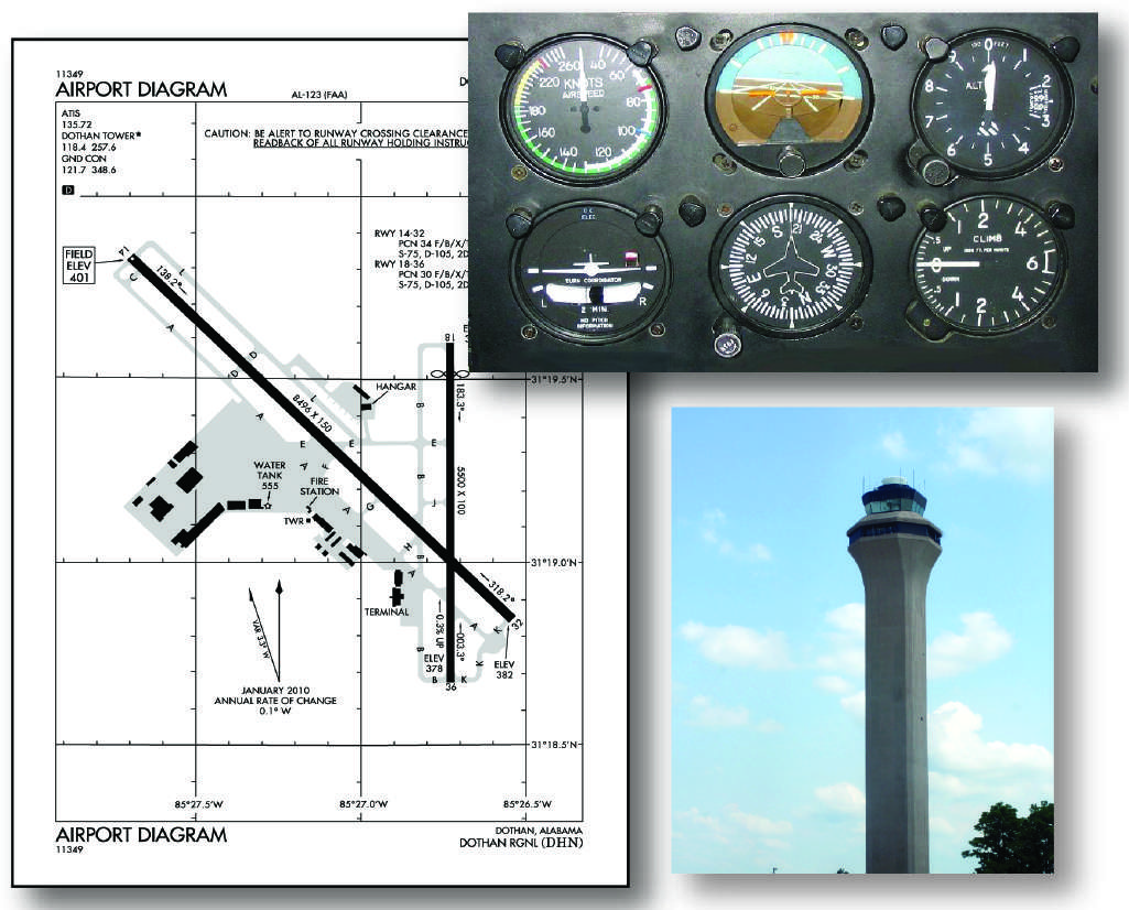
Runway Incursion Avoidance
A runway incursion is any occurrence at an airport involving an aircraft, vehicle, person, or object on the ground that creates a
collision hazard or results in a loss of separation with an aircraft taking off, landing, or intending to land. The three major areas
contributing to runway incursions are communications, airport knowledge, and flight deck procedures for maintaining orientation.
[Figure 1-12]
Figure 1-12.
Three major areas contributing to runway incursions are communications with air traffic control (ATC), airport
knowledge, and flight deck procedures.
1-12
Taxi operations require constant vigilance by the entire flight crew, not just the pilot taxiing the airplane. During flight training, the
instructor should emphasize the importance of vigilance during taxi operations. Both the learner and the flight instructor need to be
continually aware of the movement and location of other aircraft and ground vehicles on the airport movement area. Many flight
training activities are conducted at non-tower controlled airports. The absence of an operating airport control tower creates a need for
increased vigilance on the part of pilots operating at those airports.
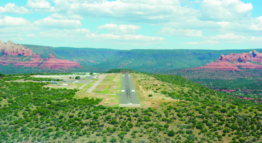
[Figure 1-13]
Figure 1-13.
Sedona Airport is one of the many airports that operate without a control tower.
Planning, clear communications, and enhanced situational awareness during airport surface operations reduces the potential for
surface incidents. Safe aircraft operations can be accomplished and incidents eliminated if the pilot is properly trained early on and
throughout their flying career on standard taxi operating procedures and practices. This requires the development of the formalized
teaching of safe operating practices during taxi operations. The flight instructor is the key to this teaching. The flight instructor should
instill in the learner an awareness of the potential for runway incursion, and should emphasize the runway incursion avoidance
procedures. For more information and a list of additional references, refer to Chapter 14 of the
Pilot’s Handbook of Aeronautical
Knowledge
.
Stall Awareness
14 CFR part 61, section 61.87 (d)(10) and (e)(10) require that a student pilot who is receiving training for a single-engine or
multiengine airplane rating or privileges, respectively, log flight training in stalls and stall recoveries prior to solo flight. [
Figure 1-14
]
During this training, the flight instructor should emphasize that the direct cause of every stall is an excessive angle of attack (AOA).
The student pilot should fully understand that there are several flight maneuvers that may produce an increase in the wing’s AOA, but
the stall does not occur until the AOA becomes excessive. This critical AOA varies from 16°–20° depending on the airplane design.
[
Figure 1-15
]
Figure 1-14.
All student pilots receive and log flight training in stalls and stall recoveries prior to their first solo flight.
1-13
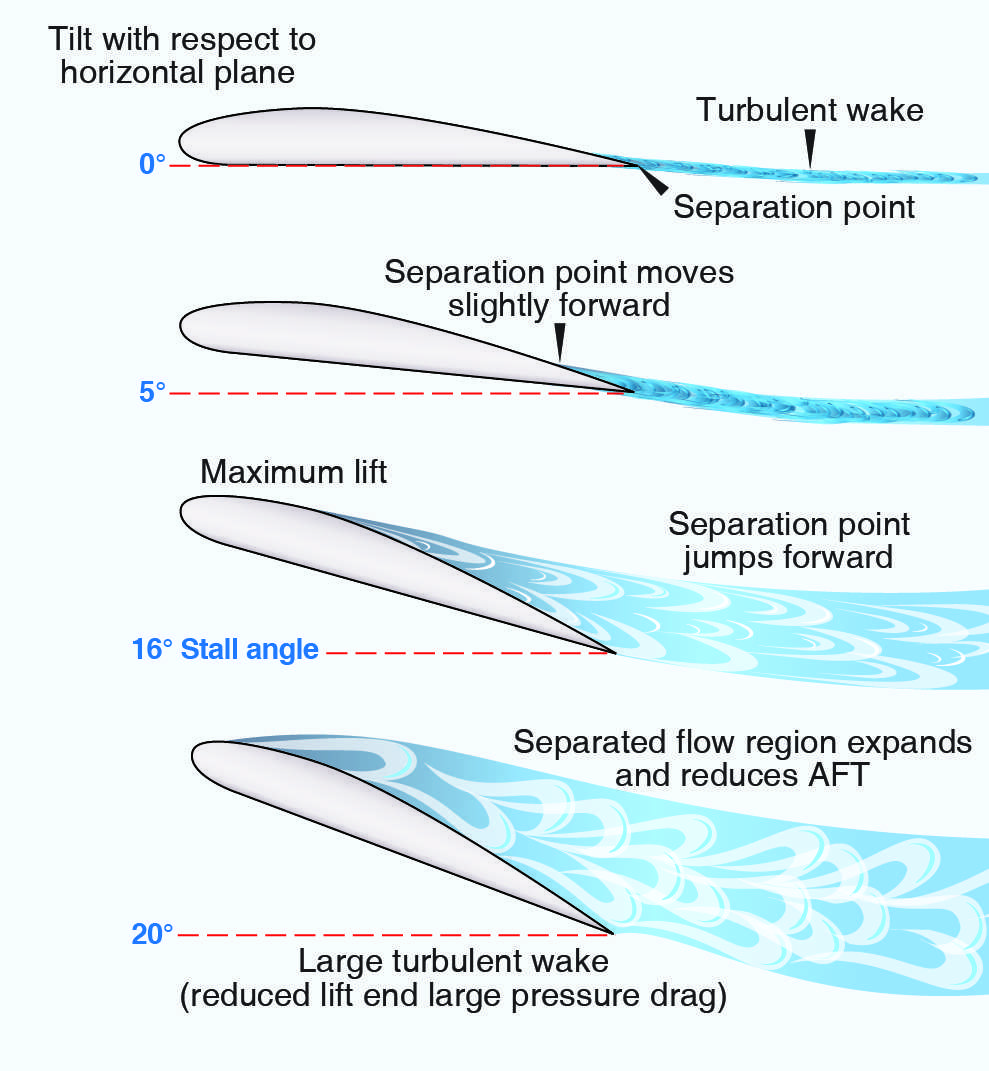
Figure 1-15.
Stalls occur when the airfoil's angle of attack reaches the critical point which can vary between 16
°
and 20
°
.
The flight instructor should emphasize that low speed is not necessary to produce a stall. The wing can be brought to an excessive
AOA at any speed. High pitch attitude is not an absolute indication of proximity to a stall. Some airplanes are capable of vertical
flight with a corresponding low AOA. Most airplanes are quite capable of stalling at a level or near level pitch attitude.
The key
to
stall awareness
is
the pilot’s
ability
to
visualize
the wing’s
AOA
in
any
particular
circumstance,
and
thereby
be able to
estimate his or her margin of safety above stall. This is a learned skill that should be acquired early in flight training and carried
through
the pilot’s
entire
flying
career.
The pilot should understand and appreciate factors such as airspeed, pitch attitude, load factor, relative wind, power setting, and
aircraft configuration
in
order
to
develop
a reasonably
accurate mental picture of
the wing’s
AOA
at any
particular
time.
It is essential
to
safety
of
flight that pilots
take into
consideration
this
visualization
of
the wing’s
AOA
prior
to
entering
any
flight maneuver.
Chapter 3, Basic Flight Maneuvers, discusses stalls in detail.
1-14
Use of Checklists
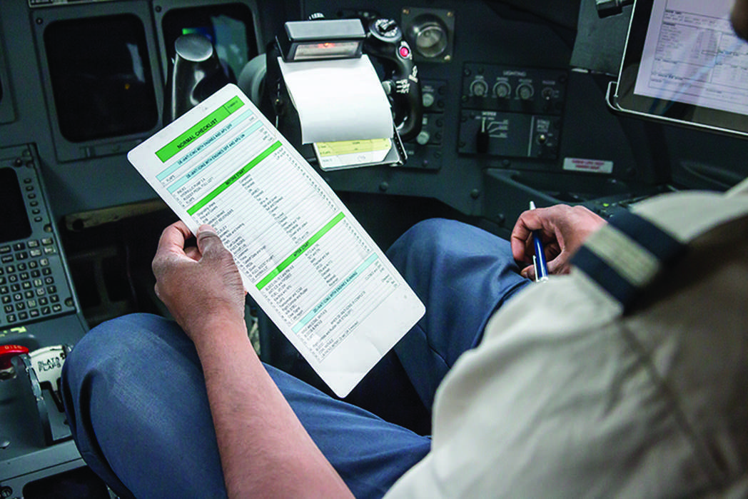
Checklists have been the foundation of pilot standardization and flight deck safety for years.
[Figure 1-16]
The checklist is a memory
aid and helps to ensure that critical items necessary for the safe operation of aircraft are not overlooked or forgotten. Checklists need
not be “do
lists.” In
other
words,
the proper
actions
can
be accomplished,
and
then
the checklist used
to
quickly
ensure all
necessary
tasks
or
actions
have been
completed
with
emphasis
on
the “check” in
checklist. However,
checklists
are of
no
value if
the pilot is not
committed to using them. Without discipline and dedication to using the appropriate checklists at the appropriate times, the odds are
on the side of error. Pilots who fail to take the use of checklists seriously become complacent and begin to rely solely on memory.
Figure 1-16.
Checklists have been the foundation of pilot standardization and flight safety for many years.
The importance of consistent use of checklists cannot be overstated in pilot training. A major objective in primary flight training is to
establish habit patterns that will serve pilots well throughout their entire flying career. The flight instructor should promote a positive
attitude toward checklist usage, and the learner should realize its importance. At a minimum, prepared checklists should be used for
the following phases of flight:
[Figure 1-17]
⦁
Preflight inspection
⦁
Before engine start
⦁
Engine starting
⦁
Before taxiing
⦁
Before takeoff
⦁
After takeoff
⦁
Cruise
⦁
Descent
⦁
Before landing
⦁
After landing
⦁
Engine shutdown and securing
1-15
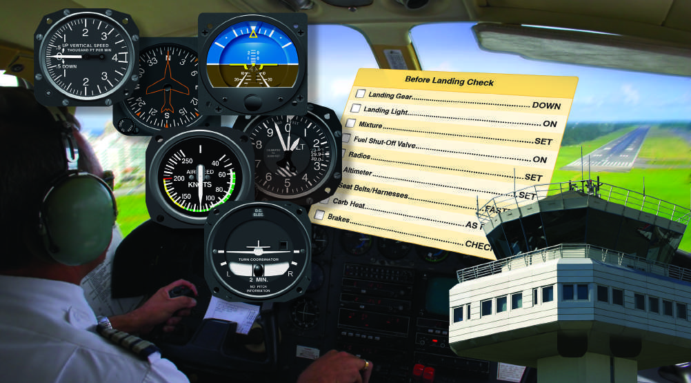
Figure 1-17.
A sample checklist used by pilots.
During flight training, there should be a clear understanding between the learner and flight instructor of who has control of the
aircraft. Prior to any flight, a briefing should be conducted that includes the procedures for the exchange of flight controls. The
following three-step process for the exchange of flight controls is highly recommended.
When
a flight
instructor
wishes
the
learner
to
take
control
of
the
aircraft,
he
or
she
should
say
to
the
learner,
“You
have
the flight
controls.”
The
learner
should
acknowledge
immediately
by
saying,
“I
have
the
flight
controls.”
The
flight
instructor
should
then
confirm
by
again
saying,
“You
have the flight controls.” Part of
the procedure should
be a visual check
to
ensure that the other person
actually has the flight controls. When returning the controls to the flight instructor, the learner should follow the same procedure the
instructor
used
when
giving
control to
the learner.
The learner
should
stay
on
the controls
until the instructor
says,
“I
have the flight
controls.” There should
never
be any
doubt as to
who
is
flying
the airplane at any
time.
Numerous
accidents
have occurred
due
to a
lack of communication or misunderstanding as to who actually had control of the aircraft, particularly between learners and flight
instructors. Establishing the above procedure during initial training ensures the formation of a very beneficial habit pattern.
Continuing Education
In many activities, the ability to receive feedback and continue learning contributes to safety and success. For example, professional
athletes receive constant coaching. They practice various techniques to achieve their best. Medical professionals read journals, train,
and master techniques to achieve better outcomes.
FAA W
INGS
Program
Compare continuous training and practice to 14 CFR part 61, section 61.56(c)(1)
and (2)
, which allows for training and a sign-off
within the previous 24 calendar months in order to act as a pilot in command. Many astute pilots realize that this regulation specifies a
minimum requirement, and the path to enhanced proficiency, safety, and enjoyment of flying takes a higher degree of
commitment such as using 14 CFR part 61, section 61.56(e). For this reason, many pilots keep their flight review up-to-date
using the FAA WINGS program. The program provides continuing pilot education and contains interesting and relevant study
materials that pilots can use all year round.
A pilot may create a WINGS account by logging on to
www.faasafety.gov
.
This account gives the pilot access to the
latest information concerning aviation technology and risk mitigation. It provides a means to document targeted skill
development as a means to increase safety. As an added bonus, participants may receive a discount on certain flight insurance
policies.
Chapter Summary
This chapter discussed some of the concepts and goals of primary and intermediate flight training. It identified and provided
an explanation of regulatory requirements and the roles of the various entities involved. It also offered recommended techniques to
be practiced and refined to develop the knowledge, proficiency, and safe habits of a competent pilot.
1-16
Airplane Flying Handbook (FAA-H-8083-3
C
)
Chapter 2: Ground Operations
Introduction
Experienced pilots place a strong emphasis on ground operations as this is where safe flight begins and ends. They know that hasty
ground operations diminish their margin of safety. A smart pilot takes advantage of this phase of flight to assess various factors
including
the regulatory
requirements,
the pilot’s
readiness
for
pilot-in-command
(PIC)
responsibilities, the airplane’s
condition,
the
flight environment, and any external pressures that could lead to inadequate control of risk.
Flying an airplane presents many new responsibilities not required for other forms of transportation. Focus is often placed on the
flying portion itself with less emphasis placed on ground operations. However pilots need to allow time for flight preparation.
Situational awareness begins during preparation and only ends when the airplane is safely and securely returned to its tie-down or
hangar, or if a decision is made not to go.
This chapter covers the essential elements for the regulatory basis of flight including:
1. An
airplane’s
airworthiness
requirements,
2. Important inspection items when conducting a preflight visual inspection,
3. Managing risk and resources, and
4. Proper and effective airplane surface movements using the AFM/POH and airplane checklists.
Preflight Assessment of the Aircraft
The visual preflight assessment mitigates airplane flight hazards. The preflight assessment ensures that any aircraft flown meets
regulatory airworthiness standards and is in a safe mechanical condition prior to flight. Per 14 CFR part 3, section 3.5(a), the
term “airworthy” means that the aircraft conforms to its type design and is in condition for safe operation. The owner/operator is
primarily responsible for maintenance, but in accordance with 14 CFR part 91, section 91.7(a) and (b) no person may operate a civil
aircraft unless it is in an airworthy condition and the pilot in command of a civil aircraft is responsible for determining whether the
aircraft is in condition for safe flight. The pilot's inspection should involve the following:
1. Inspecting
the airplane’s
airworthiness
status.
2. Following the AFM/POH to determine the required items for visual inspection.
[Figures 2-1, 2-2, 2-3]
.
Figure 2-1.
Pilots
should
view the aircraft’s maintenance
logbook prior
to
flight to
ensure the aircraft is
safe to
fly.
2-1
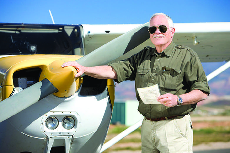
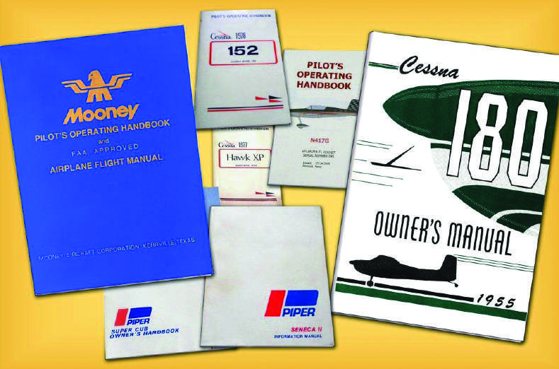
Figure 2-2.
A visual inspection of the aircraft before flight is an important step in mitigating airplane flight hazards.
Figure 2-3.
Airplane Flight Manuals (AFM) and the Pilot Operating Handbook (POH) for each individual aircraft explain the
required items for inspection.
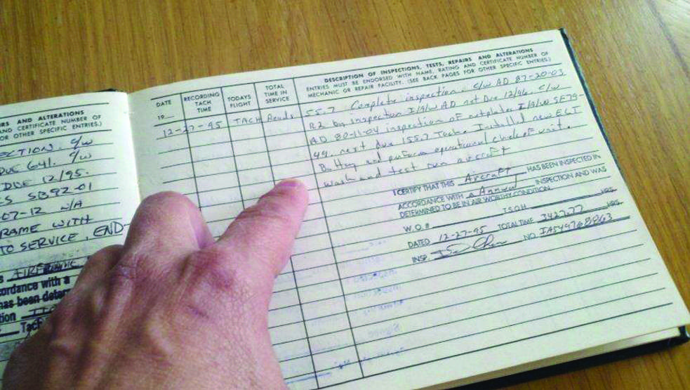
Each airplane has a set of logbooks that include airframe and engine, and in some cases, propeller and appliance logbooks, which are
used to record maintenance, alteration, and inspections performed on a specific airframe, engine, propeller, or appliance. It is
important that the logbooks be kept accurate, secure, and available for inspection. Airplane logbooks are not normally kept in the
airplane. It should be a matter of procedure by the pilot to inspect the airplane logbooks or a summary of the airworthy status prior to
flight to ensure that the airplane records of maintenance, alteration, and inspections are current and correct.
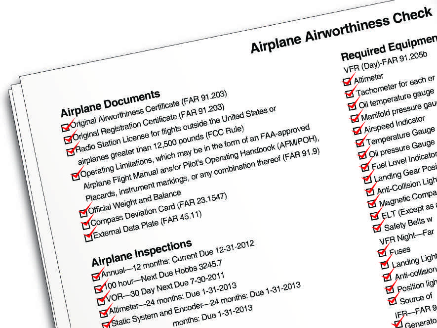
[Figure 2-4]
The
following is required:
2-2
⦁
Annual inspection within the preceding 12 calendar
months (Title 14 of the Code of Federal Regulations
(14 CFR) part 91, section 91.409(a))
⦁
100-hour inspection, if the aircraft is operated for hire (14 CFR part 91, section 91.409(b))
⦁
Transponder certification within the preceding 24 calendar months (14 CFR part 91, section 91.413)
⦁
Static system and encoder certification, within the preceding 24 calendar months, required for instrument
flight rules (IFR) flight in controlled airspace (14 CFR part 91, section 91.411)
⦁
30-day VHF omnidirectional range (VOR) equipment check when using the VOR system of radio
navigation for IFR flight (14 CFR part 91, section 91.171)
⦁
Emergency locator transmitter (ELT) inspection within the last 12 months (14 CFR part 91, section
91.207(d))
⦁
ELT battery due (14 CFR part 91, section 91.207(c))
⦁
Current status of life limited parts per Type Certificate Data Sheets (TCDS) (14 CFR part 91, section
91.417)
⦁
Status, compliance, logbook entries for airworthiness directives (ADs) (14 CFR part 91, section 91.417(a)
(2)(v))
⦁
Federal Aviation Administration (FAA) Form 337, Major Repair or Alteration (14 CFR part 91, section
91.417)
⦁
Inoperative equipment (14 CFR part 91, section 91.213)
Figure 2-4.
A sample airworthiness checklist used by pilots to inspect an aircraft.
2-3
A review determines if the required maintenance and inspections have been performed on the airplane. Any discrepancies need to be
addressed
prior
to
flight. Once
the pilot has determined
that the airplane’s
logbooks
provide factual assurance
that the airplane meets
its airworthiness requirements, it is appropriate to inspect the airplane visually. The visual preflight inspection of the airplane should
begin while approaching the airplane on the ramp. The pilot should make note of the general appearance of the airplane, looking for
discrepancies such as misalignment of the landing gear and airplane structure. The pilot should also take note of any distortions of the
wings, fuselage, and tail, as well as skin damage and any staining, dripping, or puddles of fuel or oils.
The pilot needs to determine that the following documents are, as appropriate, on board, attached, or affixed to the airplane:
⦁
Current Airworthiness Certificate (14 CFR part 91, section 91.203)
⦁
Current Registration Certificate (14 CFR part 91, section 91.203)
⦁
Radio station license for flights outside the United States or airplanes greater than 12,500 pounds (Federal
Communications Commission (FCC) rule)
⦁
Operating limitations, which may be in the form of an FAA-approved AFM/POH, placards, instrument
markings, or any combination thereof (14 CFR part 91, section 91.9)
⦁
Current weight and balance data
⦁
Compass correction card, if required under applicable airworthiness standards
⦁
External data plate (14 CFR part 45, section 45.11)
Visual Preflight Assessment
The inspection should start with the cabin door. If the door is hard to open or close, does not fit snugly, or the door latches do not
engage or disengage smoothly, the surrounding structure, such as the doorpost, should be inspected for misalignment, which could
indicate structural damage. The visual preflight inspection should continue to the interior of the cabin or flight deck where carpeting
should be inspected to ensure that it is serviceable, dry, and properly affixed; seat belts and shoulder harnesses should be inspected to
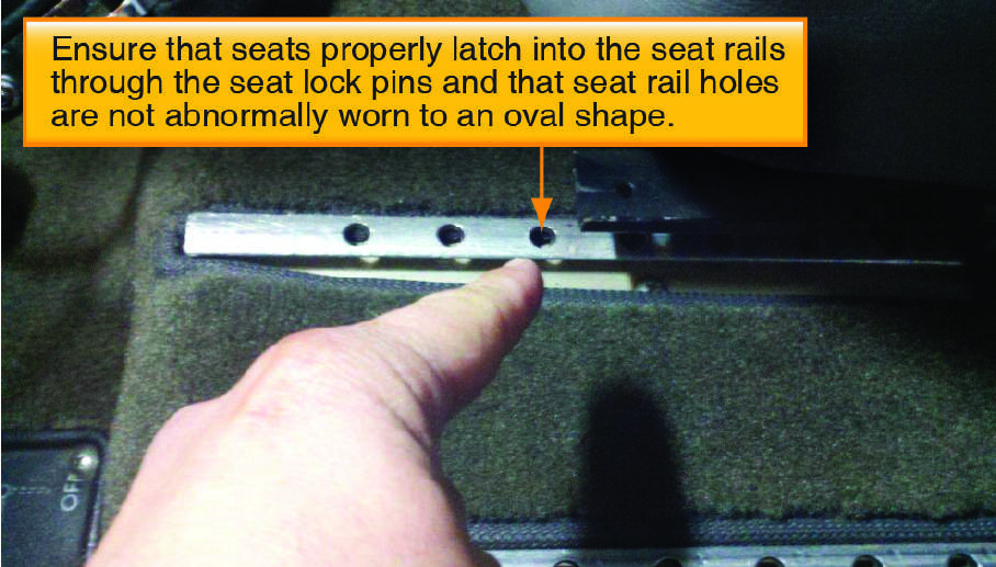
ensure that they are free from fraying, latch properly, and are securely attached to their mounting fittings; seats should be inspected to
ensure that the seats properly latch into the seat rails through the seat lock pins and that seat rail holes are not abnormally worn to an
oval shape;
[Figure 2-5]
the windshield and windows should be inspected to ensure that they are clean and free from cracks, and
crazing. A dirty, scratched, and/or a severely crazed window can result in near zero visibility due to light refraction at certain angles
from the sun.
Figure 2-5.
Seats should be inspected to ensure that they are properly latched into the seat rails and checked for damage.
2-4
The AFM/POH or a third party checklist based on the AFM/POH may be used to conduct the visual preflight inspection, and each
manufacturer has a specified sequence for conducting the actions. In general, the following items are likely to be included in the
AFM/POH preflight inspection:
⦁
Landing gear control is DOWN, if applicable.
⦁
Master, alternator, and magneto switches are OFF.
⦁
Control column locks are REMOVED.
⦁
Fuel selectors should be checked for proper operation in all positions, including the OFF position.
Stiff fuel selectors or where the tank position is not legible or lacking detents are unacceptable.
⦁
Trim wheels, which include elevator and may include rudder and aileron, are set for takeoff position.
⦁
Mechanical air-driven gyro instruments should be inspected for signs of hazing on the instrument
face, which may indicate leaks.
⦁
Avionics master is OFF.
⦁
Circuit breakers checked IN.
⦁
Confirm that the landing gear handle is in the DOWN position, then turn the master switch ON. Note
the fuel quantities on the fuel gauges and compare to the tank level by visual inspection. If so
equipped, fuel pumps may be placed in the ON position to verify fuel pressure in the proper
operating range.
⦁
Other items may include checking that lights for both the interior and exterior airplane positions are
operating and checking any annunciator panels.
⦁
If the airplane has retractable gear, landing gear down
and locked lights are checked green.
⦁
Flight instruments should read as follows:
⦁
Airspeed should read zero.
⦁
The altimeter, when properly set to the current barometric setting, should indicate the field
elevation within 75 feet for IFR flight.
⦁
If
installed,
the magnetic compass
should
indicate
the airplane’s
direction
accurately; and
the
compass correction card should be legible and complete. For conventional wet magnetic
compasses, the instrument face should be clear and the instrument case full of fluid. A cloudy
instrument face, bubbles in the fluid, or a partially filled case renders the compass unusable.
⦁
The vertical speed indictor (VSI) should read zero. If the VSI does not show a zero reading, a
small screwdriver can be used to zero this instrument if not part of an electronic display. The
mechanical VSI is the only flight instrument that a pilot has the prerogative to adjust. All others
need to be adjusted by an FAA-certificated repairman or mechanic.
⦁
Avionics master switch ON to check avionics. Avionics master switch OFF, master switch OFF.
Aircraft
equipped
with
Integrated
Flight
Deck
(IFD)
“glass-panel”
avionics
and
supporting
systems
have
specific
requirements
for
checking prior to flight.
Ground-based inspections may include verification that the flight deck reference guide is in the aircraft and
accessible;
checking
of
system
driven
removal
of
“Xs”
over
engine
indicators;
checking
pitot/static
and
attitude
displays;
testing of
low level alarms and annunciator panels; setting of fuel levels; and verification that the avionics cooling fans, if equipped,
are functional.
[Figure 2-6]
The AFM/POH specifies how these preflight inspections are to take place. Since an advanced
avionics aircraft preflight checklist may be extensive, pilots should allow time to ensure that all items are properly addressed.
2-5
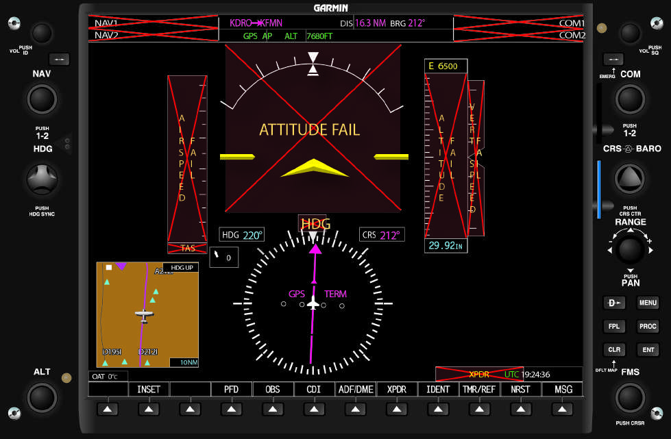
Figure 2-6.
Ground-based
inspections
include verification
that “Xs”
on
the instrument display are displayed
until the sensor
activates.
Outer Wing Surfaces and Tail Section
Generally, the AFM/POH specifies a sequence for the pilot to inspect the aircraft that may sequence from the cabin entry access
opening and then in a counterclockwise direction until the aircraft has been completely inspected. Besides the AFM/POH preflight
assessment, the pilot should also develop awareness for potential areas of concern, such as signs of deterioration or distortion of the
structure, whether metal or composite, as well as loose or missing rivets or screws.
In addition to items specified in the AFM/POH for inspection, the pilot should have an awareness for critical areas, such as spar lines,
wing, horizontal, and vertical attach points including wing struts and landing gear attachment areas. The airplane skin should be
inspected in these areas as load-related stresses are concentrated along spar lines and attach points. Spar lines are lateral rivet lines
that extend across the wing, horizontal stabilizer, or vertical stabilizer. Pilots should pay close attention to spar lines looking for
distortion, ripples, bubbles, dents, creases, or waves as any structural deformity may be an indication of internal damage or failure.
Inspect around rivet heads looking for cracked paint or a black-oxide film that forms when a rivet works free in its hole.
[Figure 2-7]
Figure 2-7.
Example of rivet heads where black oxide film has formed due to the rivet becoming loose in its hole.
2-6
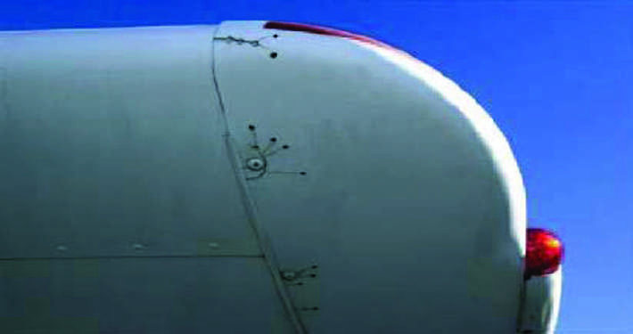
Additional areas that should be scrutinized are the leading edges of the wing, horizontal stabilizer, and vertical stabilizer. These areas
may have been impact-damaged by rocks, ice, birds, and/or hangar rash incidents. Certain dents and dings may render the structure
unairworthy. Some leading edge surfaces have aerodynamic devices, such as stall fences, slots, or vortex generators, and deicing
equipment, such as weeping wings and boots. If these items exist on the airplane, the pilot should know their proper condition so that
an adequate preflight inspection may occur.
On metal airplanes, wingtips, fairings, and non-structural covers may be fabricated out of thin fiberglass or plastic. These items are
frequently affected by cracks radiating from screw holes or concentrated radii. Often, if any of these items are cracked, it is practice
to “stop-drill” the crack to prevent crack progression.
[Figure 2-8]
Extra care should be exercised to ensure that these devices are in
good condition without cracks that may render them unairworthy. Cracks that have continued beyond a stop
-
drilled location or
any new adjacent cracks that have formed may lead to in-flight failure.
Figure 2-8.
Cracks radiating from screw holes that have been stop-drilled to prevent crack progression.
Inspecting composite airplanes can be more challenging as the airplanes generally have no rivets or screws to aid the pilot in
identifying spar lines and wing attach points. However, delamination of spar to skin or other structural problems may be identified by
bubbles, fine hair-line cracks, or changes in sound when gently tapping on the
structure with a fingertip. Anything out of place should
be addressed by discussing the issue with a properly rated aircraft mechanic.
Fuel and Oil
While there are various formulations of aviation gasoline (AVGAS), only three grades are conventional: 80/87, 100LL, and 100/130.
100LL is the most widely available in the United States. AVGAS is dyed with a faint color for grade identification: 80/87 is dyed red;
100LL is dyed blue; and 100/130 is dyed green. All AVGAS grades have a familiar gasoline scent and texture. 100LL with its blue
dye is sometimes difficult to identify unless a fuel sample is held up against a white background in reasonable white lighting.
Aircraft piston engines certificated for grade 80/87 run satisfactorily on 100LL if approved as an alternate. The reverse is not true.
Fuel of a lower grade should never be substituted for a required higher grade. Detonation will severely damage the engine in a very
short period of time. Detonation, as the name suggests, is an explosion of the fuel-air mixture inside the cylinder. During detonation,
the fuel/air charge (or pockets within the charge) explodes rather than burns smoothly. Because of this explosion, the charge exerts a
much higher force on the piston and cylinder, leading to increased noise, vibration, and cylinder head temperatures. The violence of
detonation also causes a reduction in power. Mild detonation may increase engine wear, though some engines can operate with mild
detonation regularly. However, severe detonation can cause engine failure in minutes.
[Figure 2-9]
Because of the noise that it
makes, detonation is "engine knock" or "pinging" in cars.
When approved for the specific airplane to be flown, automobile gasoline is sometimes used as a substitute fuel in certain airplanes.
Its use is acceptable only when the particular airplane has been issued a Supplemental Type Certificate (STC) to both the airframe
and engine.
Jet fuel is a kerosene-based fuel for turbine engines and a new generation of diesel-powered airplanes. Jet fuel has a
stubborn, distinctive, non-gasoline odor and is oily to the touch. Jet fuel is clear or straw
-
colored, although it may appear dyed when
mixed with AVGAS. Jet fuel has disastrous consequences when introduced into AVGAS
-
burning reciprocating airplane engines. A
reciprocating engine operating on jet fuel may start, run, and power the airplane long enough for the airplane to become airborne
,
only to have the engine fail catastrophically after takeoff.
2-7
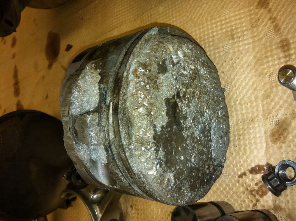
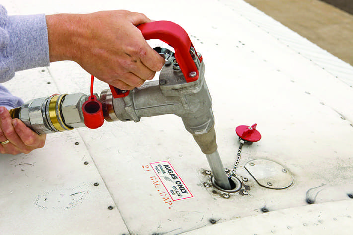
Figure 2-9.
An aircraft piston showing damage that occurred in just minutes as a result of detonation and overheating.
Jet fuel refueling trucks and dispensing equipment are marked with JET-A placards in white characters on a black background.
Because of the dire consequences associated with misfueling, fuel nozzles are specific to the type of fuel. AVGAS fuel filler nozzles
are straight with a constant diameter.
[Figure 2-10]
However, jet fuel filler nozzles are flared at the end to prevent insertion into
AVGAS fuel tanks.
[Figure 2-11]
Figure 2-10.
An AVGAS fuel filler nozzle is straight with a constant diameter.
2-8
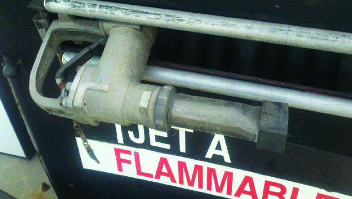
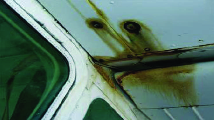
Figure 2-11.
A jet fuel filler nozzle is flared at the end to prevent an inadvertent insertion into an AVGAS tank.
Using the proper, approved grade of fuel is critical for safe, reliable engine operation. Without the proper fuel quantity, grade, and
quality, the engine(s) will likely cease to operate. Therefore, it is imperative that the pilot visually verify that the airplane has the
correct
fuel
quantity for the intended flight plus adequate and legal reserves, as well as inspect that the fuel is of the proper grade and
that the quality of the fuel is acceptable. The pilot should always ensure that the fuel caps have been securely replaced following
each fueling.
Many airplanes experience sensitivity to attitude when fueling for maximum capacity. Nosewheel or main landing gear strut
extension, both high as well as low, and the slope of the ramp can significantly alter the attitude of the aircraft and therefore the fuel
capacity. Always positively confirm the fuel quantity indicated on the fuel gauges by visually inspecting the level of fuel in each tank.
The pilot should be aware that fuel stains anywhere on the wing or any location where a fuel tank is mounted warrants further
investigation—no matter how old the stains appear to be. Fuel stains are a sign of probable fuel leakage. On airplanes equipped with
wet-wing fuel tanks, evidence of fuel leakage can be found along rivet lines.
[Figure 2-12]
Figure 2-12.
Evidence of fuel leakage can be found along rivet lines.
Checking for water and other sediment contamination is a key preflight item. Water tends to accumulate in fuel tanks from
condensation, particularly in partially filled tanks. Because water is heavier than fuel, it tends to collect in the low points of the fuel
system. Water can also be introduced into the fuel system from deteriorated gas cap seals exposed to rain or from the supplier’s
storage tanks and delivery vehicles. Sediment contamination can arise from dust and dirt entering the tanks during refueling or from
deteriorating rubber fuel tanks or tank sealant. Deteriorating rubber from seals and sealant may show up in the fuel sample as small
dark specks.
2-9
The best preventive measure is to minimize the opportunity for water to condense in the tanks. If possible, the fuel tanks should be
completely filled with the proper grade of fuel after each flight, or at least filled after the last flight of the day. The more fuel that is in
the tanks, the less room
there is
for condensation to occur. Keeping fuel tanks filled is also the best way to slow the aging of
rubber fuel tanks and tank sealant.
Sufficient fuel should be drained from the fuel strainer quick drain and from each fuel tank sump to check for fuel grade/color, water,
dirt, and odor. If water is present, it is usually in bubble or bead-like droplets, different in color (usually clear, sometimes muddy
yellow to brown with specks of dirt), in the bottom of the sample jar. In extreme water contamination cases, consider the possibility
that the entire fuel sample, particularly if a small sample was taken, is water. If water is found in the first fuel sample, continue
sampling until no water and contamination appears. Significant and/or consistent water, sediment or contaminations are grounds for
further investigation by qualified maintenance personnel. Each fuel tank sump should be drained during preflight and after refueling.
The order of sumping the fuel system is often very important. Check the AFM/POH for specific procedures and order to be followed.
Checking the fuel tank vent is an important part of a preflight assessment. If outside air is unable to enter the tank as fuel is drawn into
the engine, the eventual result is fuel starvation and engine failure. During the preflight assessment, the pilot should look for signs of
vent damage and blockage. Some airplanes utilize vented fuel caps, fuel vent tubes, or recessed areas under the wings where vents are
located. The pilot should use a flashlight to look at the fuel vent to ensure that it is free from damage and clear of obstructions. If
there is a rush of air when the fuel tank cap is cracked, there could be a serious problem with the vent system.
Aviation oils are available in various single/multi-grades and mineral/synthetic-based formulations. It is important to use the
approved and recommended oil for the engine at all times. The oil not only acts as a lubricant but also as a medium to transfer heat as
a result of engine operation and to suspend dirt, combustion byproducts, and wear particles between oil changes. Therefore, the
proper level of oil is required to ensure lubrication, effective heat transfer, and the suspension of various contaminants. The oil level
should be checked during each preflight, rechecked with each refueling, and maintained to prevent the oil level from falling below the
minimum required during engine operation.
During the preflight assessment, if the engine is cold, oil levels on the oil dipstick show higher levels than if the engine was warm and
recently shutdown after a flight. When removing the oil dipstick, care should be taken to keep the dipstick from coming in contact
with dirty or grimy areas. The dipstick should be inspected to verify the oil level. Typically, piston airplane engines have
oil reservoirs with capacities between four and eight quarts, with six quarts being common.
Aside from
the level of oil, the
oil’s color
also
provides an insight as to its operating condition. Oils darken in color as the oil operating hours increase—this
is common and expected as the oil traps contaminants. However, oils that rapidly darken in the first few hours of use after an oil
change may indicate engine cylinder problems. Piston airplane engines consume a small amount of oil during normal
operation. The amount of consumption varies on many factors; however, if consumption increases or suddenly changes, qualified
maintenance personnel should investigate
It is suggested that the critical aspect of fuel and oil
not
be left to line service personnel without oversight of the pilot responsible for
flight. While line personnel are aviation professionals, the pilot is responsible for the safe outcome of any flight. During refueling or
when oil is added to an engine, the pilot should monitor and ensure that the correct quantity, quality, and grade of fuel and oil is
added and that all fuel and oil caps have been securely replaced.
Landing Gear, Tires, and Brakes
The landing gear, tires, and brakes allow the airplane to maneuver from and return to the ramp, taxiway, and runway environment in a
precise and controlled manner. The landing gear, tires, and brakes should be inspected to ensure that the airplane can be positively
controlled on the ground. Landing gear on airplanes varies from simple fixed gear to complex retractable gear systems.
Fixed landing gear is a gear system in which the landing gear struts, tires, and brakes are exposed and lend themselves to relatively
simple inspection. However, more complex airplanes may have retractable landing gear with multiple tires per landing gear strut,
landing gear doors, over-center locks, springs, and electrical squat switches. Regardless of the system, the pilot should follow the
AFM/POH during inspection to determine that the landing gear is ready for operation.
On many fixed-gear airplanes, inspection of the landing gear system can be hindered by wheel pants, which are covers used to reduce
aerodynamic
drag.
It
is
still
the
pilot’s
responsibility
to
inspect
the
airplane
properly.
A
flashlight
helps
the
pilot
in
peering into
covered areas. On low-wing airplanes, covered or retraceable landing gear presents additional effort required to crouch below the
wing to inspect the landing gear properly.
The following provides guidelines for inspecting the landing gear system; however, the AFM/POH should be the pilot’s reference for
the appropriate procedures.
2-10
⦁
The pilot, when approaching the airplane, should look at the landing gear struts and the adjacent ground for
leaking hydraulic fluid that may be coming from struts, hydraulic lines from landing gear retraction pumps,
or from the braking system. Landing gear should be relatively free from grease, oil, and fluid without any
undue amounts. Any amount of leaking fluid is unacceptable. In addition, an overview of the landing gear
provides an opportunity to verify landing gear alignment and height consistency.
⦁
All landing gear shock struts should also be checked to ensure that they are properly inflated, clean, and
free from hydraulic fluid and damage. All axles, links, collars, over-center locks, push rods, forks, and
fasteners should be inspected to ensure that they are free from cracks, corrosion,
and
rust, and
are in an
airworthy
condition
.
⦁
Tires should be inspected for proper inflation, an acceptable level of remaining tread, and normal wear
pattern. Abnormal wear patterns, sidewall cracks, and damage, such as cuts, bulges, imbedded foreign
objects, and visible cords, render the tire unairworthy. For airplanes that are flown by more than one pilot,
what happened to the tires on previous flights becomes a significant unknown. Therefore, when possible,
the airplane should be moved slightly to allow for evaluation of the complete tire circumference.
⦁
Wheel hubs should be inspected to ensure that they are free from cracks, corrosion, and rust, that all
fasteners are secure, and that the air valve stem is straight, capped, and in good condition.
⦁
Brakes and brake systems should be checked to ensure
that they are free from rust and corrosion and that
all fasteners and safety wires are secure. Brake pads should have a proper amount of material remaining and
should be secure. All brake lines should be secure, dry, and free of signs of hydraulic leaks, and devoid of
abrasions and deep cracking.
⦁
On tricycle gear airplanes, a shimmy damper is used to damp oscillations of the nose gear and should be
inspected to ensure that it is securely attached, is free of hydraulic fluid leaks, and is in overall good
condition. Some shimmy dampers do not use hydraulic fluid and instead use an elastomeric compound as
the dampening medium. Nose gear links, collars, steering rods, and forks should be inspected to ensure the
security of fasteners, minimal free play between torque links, crack-free components, and for proper
servicing and general condition.
⦁
On some conventional gear airplanes, those airplanes with a tailwheel or skid, the main landing gear may
have bungee cords to help in absorbing landing loads and shocks. The bungee cords must be inspected for
security and condition.
⦁
Where the landing
gear
transitions
into
the airplane’s
structure,
the pilot should
inspect the attachment
points and the airplane skin in the adjacent area—the pilot needs to inspect for wrinkled or other damaged
skin, loose bolts, and rivets and verify that the area is free from corrosion.
Engine and Propeller
Properly managing the risks associated with flying requires that the pilot of the airplane identify and mitigate any potential hazards
prior to flight to prevent, to the furthest extent possible, a hazard becoming a realized risk. The engine and propeller make up the
propulsion system of the airplane—failure of this critical system requires a well-trained and competent pilot to respond with
significant time constraints to what is likely to become a major emergency.
The pilot needs to ensure that the engine, propeller, and associated systems are functioning properly prior to operation. This starts
with an overview of the cowling that surrounds the airplane engine. The pilot should look for loose, worn, missing, or damaged
fasteners, rivets, and latches that secure the cowling around the engine and to the airframe. The pilot should be vigilant as fasteners
and rivets can be numerous and surround the cowling requiring a visual inspection from above, the sides, and the bottom. Like other
areas on the airframe, rivets should be closely inspected for looseness by looking for signs of a black oxide film around the rivet head.
The pilot should pay attention to chipped or flaking paint around rivets and other fasteners as this may be a sign of a lack of security.
Any cowling security issues need to be referred to a competent and rated airplane maintenance mechanic.
2-11
From the cowling, a general inspection of the propeller spinner, if so equipped, should be completed. Not all airplane/propeller
combinations have a spinner, so adherence to the AFM/POH checklist is required. Spinners are subjected to great stresses and should
be inspected to be free from dents, cracks, corrosion, and in proper alignment. Cracks may not only occur at locations where fasteners
are used but also on the rear
-
facing spinner plate. In conditions where ice or snow may have entered the spinner around the propeller
openings, the pilot should inspect the area to ensure that the spinner is internally free from ice. The engine/propeller/spinner is
balanced around the crankshaft and a small amount of ice or snow can produce damaging vibrations. Cracks, missing fasteners, or
dents result in a spinner that is unairworthy.
The propeller should be checked for blade erosion, nicks, cracks, pitting, corrosion, and security. On controllable pitch propellers, the
propeller hub should be checked for oil leaks that tend to stream directionally from the propeller hub toward the tip. On airplanes so
equipped, the alternator/generator drive belts should be checked for proper tension and signs of wear.
When inspecting inside the cowling, the pilot should check all surfaces for oil leaks or deterioration of oil and hydraulic lines, and
make certain that the oil cap, filter, oil cooler, and drain plug are secure. The pilot should look for signs of fuel dye, which may
indicate a fuel leak. Note that both fuel and oil stains may appear on a cowling inner surface. Observation may be difficult without the
aid of a flashlight, so even during day operations, a flashlight is handy when peering into the cowling. The pilot should also check for
loose or foreign objects inside the cowling, such as bird nests, shop rags, and/or tools. All visible wires and lines should be checked
for security and condition. The exhaust system should be checked for white stains caused by exhaust leaks at the cylinder head or
cracks in the exhaust stacks. The heat muffs, which provide cabin heating on some airplanes, should also be checked for general
condition and signs of cracks or leaks. An isolated area of oxidized darkened paint on the engine may indicate an area experiencing
excessive heat. If visible, the condition of the firewall may be checked for integrity.
The air filter should be checked to ensure that it is free from substantial dirt or restrictions, such as bugs, birds, nests, or other causes
of airflow restriction. In addition, air filter elements are made from various materials. In all cases, the element should be free from
decomposition and properly serviced.
Risk and Resource Management
Ground
operations
also
include the pilot’s
assessment of
the risk
factors
that contribute to
safety
of
flight and
the pilot’s
management
of
the
resources,
which
may
be
leveraged
to
maximize
the
flight’s
successes.
The
Risk
Management
Handbook
(FAA-H-8083-2)
should be reviewed for a comprehensive discussion of this topic. A review of key points follows.
Approximately 85 percent of all aviation accidents have been determined by the National Transportation Safety Board (NTSB) to
have
been
caused
by
“failure
of
the
pilot
to...”
As
such,
a reduction
of
these
failures
is
the
fundamental
cornerstone
to
risk and
resource management. The risks involved with flying an airplane are very different from those experienced in daily activities, such as
driving to work. Managing risks and resources requires a conscious effort that goes beyond the stick and rudder skills required to
pilot the airplane.
Risk Management
Risk management is a formalized structured process for identifying and mitigating hazards and assessing the consequences and
benefits of the accepted risk. A hazard is a condition, event, object, or circumstance that could lead to or contribute to an unplanned
or undesired event, such as an incident or accident. It is a source of potential danger. Some examples of hazards are:
1.
Marginal weather or environmental conditions
2.
Lack of pilot qualification, currency, or proficiency for the intended flight
.
Identifying the Hazard
Hazard identification is the critical first step of the risk management process. If pilots do not recognize and properly identify a hazard
and choose to continue, the consequences of the risk involved is not managed or mitigated. In the previous examples, the hazard
identification process results in the following assessment:
⦁
Marginal weather or environmental conditions is an identified hazard because it may result in the pilot
having a skill level that is not adequate for managing the weather conditions or requiring airplane
performance that is unavailable.
⦁
The lack of pilot training is an identified hazard because the pilot does not have experience to either meet
the legal requirements or the minimum necessary skills to safely conduct the flight.
2-12
Risk
Risk is the future impact of a hazard that is not controlled or eliminated. It can be viewed as future uncertainty created by the hazard.
⦁
If the weather or environmental conditions are not properly assessed, such as in a case where an airplane
may encounter inadvertent instrument conditions, loss of airplane control may result.
⦁
If
the pilot’s
lack
of
training
is
not properly
assessed,
the pilot may
be placed
in
flight regimes that exceed
the pilot’s stick
-
and
-
rudder capability.
Risk Assessment
Risk assessment determines the degree of risk and whether the degree of risk is worth the outcome of the planned activity. Once the
planned activity is started, the pilot needs to consider whether to continue or not. A pilot should always have viable alternatives
available in the event the original flight plan cannot be accomplished. Thus, hazard and risk are the two defining elements of risk
management. A hazard can be a real or perceived condition, event, or circumstance that a pilot encounters. Risk assessment is a
quantitative value weighted to a task, action, or event. When armed with the predicted risk assessment of an activity, pilots are able to
manage and mitigate their risk.
In the example where marginal weather is the identified hazard, it is relatively simple to understand that the consequences of loss of
control
during any inadvertent encounter with
instrument
meteorological conditions (IMC) are likely to be severe for a pilot
not
prepared to fly on an
instrument flight
plan
. A risk assessment
for any such pilot
in this example would determine that the risk is
unacceptable and as a result, mitigation of the risk is required. Proper risk mitigation would require that flight be
canceled
or delayed
until weather conditions were not conducive for inadvertent flight into instrument meteorological conditions.
Risk Identification
Identifying hazards and associated risk is key to preventing risk and accidents. If a pilot fails to search for risk, it is likely that he or
she will neither see it nor appreciate it for what it represents. Unfortunately, in aviation, pilots seldom have the opportunity to learn
from their small errors in judgment because even small mistakes in aviation are often fatal. In order to identify risk, the use
of standard procedures is of great assistance. Several procedures are discussed in detail in the Risk Management Handbook
(FAA-H-8083-2).
Risk Mitigation
Risk assessment is only part of the equation. After determining the level of risk, the pilot needs to mitigate the risk. For example,
the VFR pilot flying from point A to point B (50 miles) in marginal flight conditions has several ways to reduce risk:
1. Wait for the weather to improve to good VFR conditions.
2.
Take a pilot who is more experienced or who is
certified as an instrument flight rules (IFR) pilot.
3. Delay the flight.
4. Cancel the flight.
5. Drive.
Resource Management
Familiarity with crew resource management (CRM) and single-pilot resource management (SRM) enables a crew or pilot to manage
all available resources effectively and leads to a successful flight. In general aviation, SRM comes into play more often. The focus of
SRM is on the single-pilot operation. SRM integrates the following:
⦁
Situational Awareness
⦁
Human Resource Management
⦁
Task Management
⦁
Aeronautical Decision-making (ADM)
Situational Awareness
Situational awareness is the accurate perception of operational and environmental factors that affect the flight. It is a logical analysis
based upon the airplane, external support, environment, and the pilot. It is awareness on what is happening in and around the flight.
Human Resource Management
Human
r
esource
m
anagement requires an effective use of all available resources: human, equipment, and information.
2-13
Human resources include the essential personnel routinely working with the pilot to ensure safety of flight. These people include, but
are not limited to: weather briefers, flight line personnel, maintenance personnel, crew members, pilots, and air traffic personnel.
Pilots need to communicate effectively with these people. This is accomplished by using the key components of the communication
process: inquiry, advocacy, and assertion. Pilots should recognize the need to seek enough information from these resources to make
a valid
decision.
After
the necessary
information
has been
gathered,
the pilot’s
decision
should
be passed
on
to
those concerned, such
as air traffic controllers, crewmembers, and passengers. The pilot may have to request assistance from others and be assertive to
resolve some situations safely.
Equipment
in
many
of
today’s
aircraft
includes
automated
flight
and
navigation
systems.
These
automatic
systems,
while
providing
relief from many routine tasks, present a different set of problems for pilots. The automation intended to reduce pilot workload
essentially removes the pilot from the process of managing the aircraft, thereby reducing situational awareness and leading to
complacency. Information from these systems needs to be continually monitored to ensure proper situational awareness. Pilots should
be aware of both equipment capabilities and equipment limitations in order to manage those systems effectively and safely.
Information workloads and automated systems, such as autopilots, need to be properly managed to ensure a safe flight. By planning
ahead, a pilot can effectively reduce workload during critical phases of flight and prevent erosion of performance. The pilot who
effectively manages his or her workload completes routine tasks as early as possible to preclude the possibility of becoming
overloaded and stressed in the later, more critical stages of the flight.
Task Management
Pilots
have a limited
capacity
for
information.
Once
information
flow
exceeds
the pilot’s
ability
to
process
the information
mentally,
any additional information becomes unattended or displaces other tasks and information already being processed. In addition,
distraction and fixation impede the ability to process information. For example, if a pilot becomes distracted and fixates on an
instrument light failure, the unnecessary focus displaces capability and prevents appreciation of tasks of greater importance.
Aeronautical Decision-Making (ADM)
Flying safely requires the effective integration of three separate sets of skills: stick-and
-
rudder skills needed to control the airplane;
skills related to proficient operation of aircraft systems; and ADM skills. The ADM process addresses all aspects of decision-making
in the flight deck and identifies the steps involved in good decision-making. While the ADM process does not eliminate errors, it
helps the pilot recognize errors and enables the pilot to manage the error to minimize its effects. These steps are:
1. Identifying personal attitudes hazardous to safe flight;
2. Learning behavior modification techniques;
3. Learning how to recognize and cope with stress;
4. Developing risk assessment skills;
5. Using all resources; and
6. Evaluating
the effectiveness
of
one’s
own
personal ADM
skills.
Ground Operations
The airport ramp can be a complex environment with airport personnel, passengers, trucks, other vehicles, aircraft, and errant people
and animals. The pilot is responsible for the operation of the airplane and should operate safely at all times. Ground operations
subject the pilot to unique hazards, and mitigating those hazards requires proper planning and good situational awareness in the
ground environment. A mitigation tactic involves reviewing the airport diagram prior to operating and having it readily available at
all times. Whether departing to or from the ramp, the pilot needs to understand and capably manage the following:
1. Refueling operations
2. Passenger and baggage security and loading
3. Ramp and taxi operations
4. Standard ramp signals
During refueling operations, it is advisable that the pilot remove all passengers from
the
aircraft and witness the refueling to ensure
that the correct fuel and quantity is dispensed into the airplane and that any caps and cowls are properly secured after refueling.
Passengers may have little experience with the open ramp of an airport. The pilot should ensure the safety of the passengers by
cautioning them to move on the surface only as directed. If not under the pilot's direct supervision, passengers should have an escort
to ensure their safety and ramp security. Baggage loading and security should also be supervised by the pilot. Unsecured baggage or
improperly loaded baggage may adversely affect the center of gravity of the aircraft.
2-14
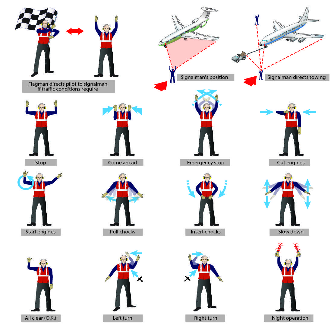
Ramp traffic may vary from a deserted open space to a complex environment with heavy corporate or military aircraft. Powerful
aircraft may produce exhaust blast or rotor downwash, for example, which could easily cause a light airplane to become
uncontrollable. Mitigating these hazards in a light airplane is important to starting off on a safe flight.
Some ramps may be staffed by personnel to assist the pilot in managing a safe departure from the ramp to the taxiway.
Figure 2-13
shows standard aircraft taxiing signals, such as those published in the Aeronautical Information Manual (AIM). There are other
standard signals, such as those published in Advisory Circular 00-34, as revised, and by the Armed Forces. Furthermore, operation
conditions in many areas may call for a modified set of taxi signals. The signals shown in
Figure 2-13
represent a minimum number
of the most commonly used signals. Whether this set of signals or a modified set is used is not the most important consideration, as
long as each flight operational center uses a suitable, agreed-upon set of signals.
Figure 2-13.
Standard hand signals used to assist pilots in managing a safe departure from the ramp to the taxiway or runway. Note
that at night, the Emergency Stop signal is used for all stop indications .
2-15
Engine Starting
Airplane engines vary substantially and specific procedures for engine starting should be accomplished in reference to
the
approved engine start checklist as detailed in the airplane’s AFM/POH. However, some generally accepted hazard mitigation
practices and procedures are outlined in this section.
Prior to engine start, the pilot needs to ensure that the ramp area surrounding the airplane is clear of persons, equipment, and other
hazards that could come into contact with the airplane or the propeller. Also, the pilot should check what is behind the airplane prior
to engine start as standard practice. A propeller or other engine thrust can accelerate ob
j
ects to substantial velocities, causing damage
to property, and injuring those on the ground. The pilot should mitigate the hazard of debris being blown into persons or property. At
all times before engine start, the anti-collision lights should be turned on. For night operations, the position (navigation) lights should
also
be
on.
Finally,
just
prior
to
starter
engagement,
the
pilot
should
always
call
“CLEAR”
out
of
the
side
window
and
wait
for a
response from anyone who may be nearby
before
engaging the starter.
When activating the starter, the wheel brakes need to be depressed and one hand kept on the throttle to manage the initial starting
engine speed. Ensuring that properly operating brakes are engaged prior to starter engagement prevents the airplane from rapidly
lunging forward. After engine start, the pilot manipulates the throttle to set the engine revolutions per minute (rpm)
to
the AFM/POH
-
prescribed setting. In general, 1,000 rpm is recommended following engine start to allow oil pressure to rise and to minimize undue
engine wear due to insufficient lubrication at high rpm. It is important to service an airplane engine with the proper grade of oil for
the seasonal conditions and to apply engine preheat when temperatures approach and descend below freezing.
The oil pressure should be monitored after engine start to ensure that pressure is increasing toward the AFM/POH
-
specified value.
The AFM/POH specifies an oil pressure range for the engine. If the limits are not reached and maintained, serious internal engine
damage is likely. In most conditions, oil pressure should rise to at least the lower limit within 30 seconds. To prevent damage, the
engine should be shut down immediately if the oil pressure does not rise to the AFM/POH values within the required time.
Engine starters are electric motors designed to produce rapid rotation of the engine crankshaft for starting. These electric motors are
not
designed for continuous duty. Their service life may be drastically shortened during a prolonged or difficult start as an ex
c
ess
buildup of heat can damage internal starter components. Avoid continuous starter operation for periods longer than 30 seconds
without a cool down period of at least 30 seconds to 1 minute (some AFM/POH specify longer cool down routines). The smell
of burning insulation from a starter may indicate that the recommended cranking time has been exceeded. After repeated
unsuccessful start attempts, the pilot should seek advice from a qualified person to determine the cause for the difficulty.
Although quite rare, the starter motor may remain electrically and mechanically engaged after engine start. This can be detected by a
continuous and very high current draw on the ammeter. Some airplanes also have a starter engaged warning light specifically for this
purpose. The engine should be shut down immediately if this occurs.
The pilot should be attentive for sounds, vibrations, smell
s
, or smoke that are not consistent with normal after
-
start
operational experience. Any concerns should lead to a shutdown and further investigation.
Hand Propping
The procedures for hand propping should always be in accordance with the AFM/POH and performed only by persons who are
competent with hand propping procedures. The consequences of the hazards associated with hand propping are serious to fatal.
Historically,
when
aircraft
lacked
electrical
systems,
it was
necessary
for
pilots
and
ground
personnel to
“hand
prop” an
aircraft for
starting. Today, most airplanes are equipped with electric starters, and the starter should be working if the airplane is airworthy. If
not, a certificated Aviation Maintenance Technician should be called to make a repair. However, vintage airplanes may be
encountered, and an airplane manufactured without an electric starter needs to be hand propped. Since a number of these airplanes
have been produced, the procedures for hand propping are described in this section.
A few simple precautions help to avoid accidents when hand propping the engine. While touching a propeller, always assume that the
ignition is on. The switches that control the magnetos operate on the principle of short-circuiting the current to turn the ignition off. If
the switch
is
faulty,
it can
be in
the “off” position
and
still
permit current to
flow
in
the magneto
primary
circuit. This
condition could
allow the engine to start when the switch is off.
Hand propping an aircraft is a hazardous procedure when done perfectly. Not mitigating the hazards associated with hand propping
can lead to serious injury and a runaway airplane. A spinning propeller can be lethal should it strike someone. Persons not trained, not
competent, or who do not understand how to mitigate the hazards associated with hand propping should
never
perform this
procedure!
2-16
Hand propping requires a team of two properly trained people. Both individuals should be familiar with the airplane and hand
propping techniques. The first person is responsible for directing the procedure including pulling the propeller blades through. The
second person sits in the airplane to ensure that the brakes are set and to exercise controls as directed by the person pulling the
propeller. When hand propping occurs, a person unfamiliar with the controls should
never
occupy
the pilot’s
seat.
When hand propping is necessary, the ground surface near the propeller should be stable and free of debris. Loose gravel, wet grass,
grease, mud, oil, ice, or snow might cause the person pulling the propeller through to slip into the rotating blades as the engine starts.
Unless a firm footing is available, relocate the airplane to mitigate this hazardous consequence.
Both participants should discuss the procedure and agree on voice commands and expected actions. To begin the procedure, the fuel
system and engine controls (tank selector, primer, pump, throttle, and mixture) are set for normal start. The ignition/magneto switch
should be checked to be sure that it is OFF. Then
,
the descending propeller blade should be rotated so that it assumes a
position slightly above the horizontal. The person doing the hand propping should face the descending blade squarely and stand
slightly less than one arm’s length from the blade. If a stance too far away were assumed, it would be necessary to lean forward in an
unbalanced condition to reach the blade, which may cause the person to fall forward into the rotating blades when the engine
starts. Allowing space for the person to be able to step away as the propeller is pulled down, and the engine starts, serves as
safeguard in case the brakes fail.
The procedure and commands for hand propping are:
⦁
Person
out front says,
“FUEL
ON,
SWITCH OFF, THROTTLE
CLOSED,
BRAKES SET.”
⦁
Pilot seat occupant, after making sure the fuel is ON,
mixture is RICH, magneto switch is OFF, throttle is
CLOSED,
and
brakes are SET,
says,
“FUEL
ON,
SWITCH OFF, THROTTLE
CLOSED,
BRAKES SET.”
⦁
Person
out front, after
pulling
the propeller
through
to
prime the engine says,
“BRAKES AND CONTACT.”
⦁
Pilot seat occupant checks
the brakes SET
and
turns
the magnetos
switch
ON,
then
says,
“BRAKES AND
CONTACT.”
The words CONTACT (magnetos ON) and SWITCH OFF (magnetos OFF) are used because they are significantly different from
each other. Under noisy conditions or high winds, the words CONTACT and SWITCH OFF are less likely to be misunderstood than
SWITCH ON and SWITCH OFF.
The propeller is swung by forcing the blade downward rapidly, pushing with the palms of both hands. If the blade is gripped tightly
with
the
fingers,
the
person’s
body
may
be
drawn
into
the
propeller
blades
should
the
engine
misfire,
"kickback,"
or
rotate
momentarily in the opposite direction. As the blade is pushed down, the person should step backward, away from the propeller. If the
engine does not start, the propeller should not be repositioned for another attempt until it is verified that the magneto switch is turned
OFF. Excessive throttle opening after the engine has fired is the principal cause of backfiring during starting. Gradual opening of the
throttle, while the engine is cold, reduces the potential for backfiring. Slow, smooth movement of the throttle assures correct engine
operation.
Immediately after the engine starts, check the oil pressure indicator. If oil pressure does not show within 30 seconds, stop the engine
and
determine
the
trouble.
If
oil
pressure
is
indicated,
adjust
the
throttle
to
the
aircraft
manufacturer’s
specified
rpm
for
engine
warmup, which is usually between 1,000 to 1,300 rpm.
Most aircraft reciprocating engines are air
-
cooled and depend on the forward speed of the aircraft to maintain proper cooling.
Therefore, particular care is necessary when operating these engines on the ground. During all ground running, operate the engine
with the propeller in full low pitch and headed into the wind with the cowling installed to provide the best degree of engine cooling.
Closely monitor the engine instruments at all times. Do not close the cowl flaps for engine warm-up, they need to be in the open
position while operating on the ground. When warming up the engine, ensure that personnel, ground equipment that may be damaged,
or other aircraft are not in the propeller wash.
When removing the wheel chocks or untying the tail after the engine starts, everyone involved should remember that the propeller is
nearly invisible. Serious injuries and fatalities have occurred when people who have just started an engine walk or reach into the
propeller arc to remove the chocks, reach the cabin, or when moving toward the tail of the airplane. Before the wheel chocks are
removed, the throttle should be set to idle and the chocks approached only from the rear of the propeller. One should never approach
the wheel chocks from the front or the side.
2-17
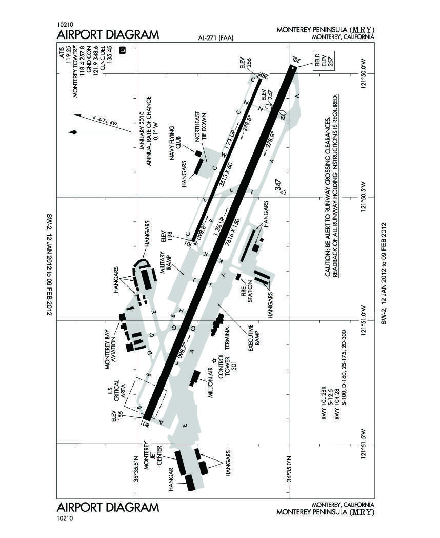
Taxiing
Taxiing is the controlled movement of the airplane under its own power while on the surface. Since an airplane is moved under its
own power between a parking area and the runway, the pilot needs to understand and be proficient in taxi procedures.
A pilot should maintain situational awareness of the ramp, parking areas, taxiways, runway environment, and the persons, equipment
and aircraft at all times. Without such awareness, safety may be compromised. Depending on the airport, the parking, ramp, and
taxiways may or may not be controlled. As such, it is important that the pilot completely understands the operating environment. At
small, rural airports these areas may be desolate with few aircraft and limited hazards; however, as the complexity of the airport
increases so does the potential for hazards. Regardless of the complexity, some generally accepted procedures are appropriate.
⦁
The pilot should be familiar with the parking, ramp, and taxi environment. This can be done by having an
airport diagram, if available, out and in view at all times.
[Figure 2-14]
Figure 2-14.
Airport Diagram of Monterey Peninsula (MRY), Monterey, California.
2-18
⦁
Despite having familiarity with the airport, pilots should carefully review their complete taxi plan. For
example, a pilot given the same taxi instructions by ATC, starts expecting those same instructions and
might not realize that those instructions no longer apply. It only takes missing one instruction or turn to
generate an accident. It is a human tendency to follow the same procedure over and over. This expectation
bias has occurred to many pilots who did not stop and carefully consider and evaluate their taxi instructions.
⦁
The pilot should be vigilant of the entire area around the airplane to ensure that the airplane clears all
obstructions. If, at any time, there is doubt about a safe clearance from an object, the pilot should stop the
airplane and check the clearance. It may be necessary to have the airplane towed or physically moved by a
ground crew.
⦁
When
taxiing,
the pilot’s
eyes should
be looking
outside the airplane scanning
from
side to
side while
looking both near and far to assess routing and potential conflicts.
⦁
A safe taxiing speed should be maintained. The primary requirements for safe taxiing are positive control,
the ability to recognize any potential hazards in time to avoid them, and the ability to stop or turn where and
when desired, without undue reliance on the brakes. Pilots should proceed at a cautious speed on congested
or busy ramps. Normally, the speed should be at the rate where movement of the airplane is dependent on
the throttle. That is, slow enough so when the throttle is closed, the airplane can be stopped promptly.
⦁
The pilot should place the aircraft on the taxiway center. Some taxiways have above
-
ground taxi lights and
signage that could impact the airplane or propellers if the pilot does not exercise accurate control. When
yellow taxiway centerline stripes are present, the pilot should visually place the centerline stripe so it is
under the center of the airplane fuselag
e.
⦁
W
hen taxiing, the pilot should slow down before attempting a turn. Sharp high-speed turns place undesirable
side loads on the landing gear and may result in tire damage or an uncontrollable swerve or a ground loop.
Swerves are most likely to occur when turning from a downwind heading toward an upwind heading. In
moderate to high-wind conditions, the airplane may weathervane increasing the swerving tendency.
Steering is accomplished with rudder pedals and brakes. To turn the airplane on the ground, the pilot should apply the rudder in the
desired direction of turn and use the appropriate power or brake to control the taxi speed. The rudder pedal should be held in the
direction of the turn until just short of the point where the turn is to be stopped. Rudder pressure is then released or
opposite
pressure
is applied as needed.
More engine power may be required to start the airplane moving forward, or to start a turn, than is required to keep it moving in any
given direction. When using additional power, the throttle should immediately be retarded once the airplane begins moving to prevent
excessive acceleration.
The brakes should be tested for proper operation as soon as the airplane is put in motion. Applying power to start the airplane moving
forward slowly, then retarding the throttle and simultaneously applying just enough pressure to one side, then the other to confirm
proper function and reaction of both brakes. This is best if the airplane has individual left/right brakes to stop the airplane. If braking
performance is unsatisfactory, the engine should be shut down immediately.
When taxiing at appropriate speeds in no-wind conditions, the aileron and elevator control surfaces have little or no effect on
directional control of the airplane. These controls should not be considered steering devices and should be held in a neutral position.
When taxiing with a quartering headwind, the wing on the upwind side (the side that the wind is coming from) tends to be lifted by
the wind unless the aileron control is held in that direction (upwind aileron UP). Moving the aileron into the UP position reduces the
effect of the wind striking that wing, thus reducing the lifting action. This control movement also causes the downwind aileron to be
placed in the DOWN position, thus a small amount of lift and drag on the downwind wing, further reducing the tendency of
the upwind wing to rise.
[Figure
2
-15]
When taxiing with a quartering tailwind, the elevator should be held in the DOWN position, and the upwind aileron, DOWN. Since
the wind is striking the airplane from behind, these control positions reduce the tendency of the wind to get under the tail and the
wing and to nose the airplane over. The application of these crosswind taxi corrections helps to minimize the weathervaning tendency
and ultimately results in easier steering.
[Figure
2
-15]
2-19
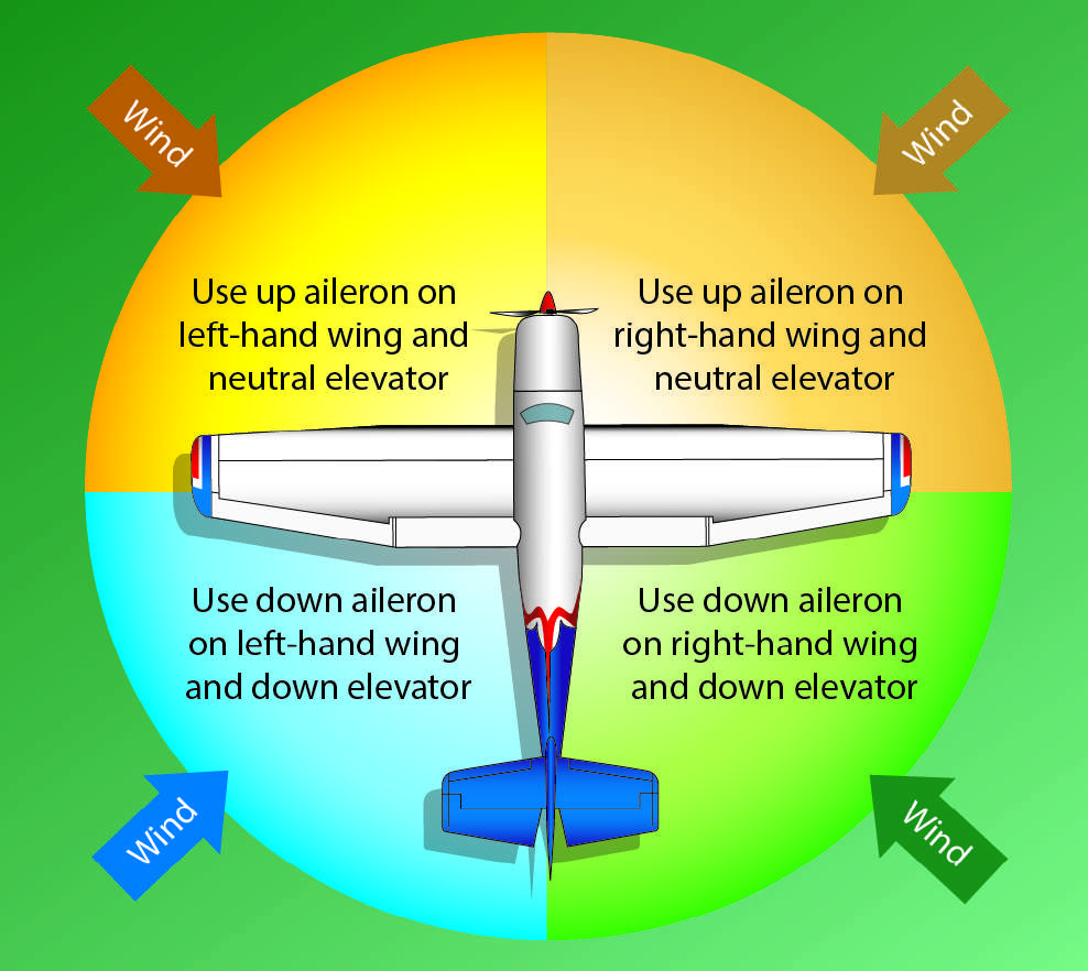
The presence of moderate to strong headwinds and/or a strong propeller slipstream creates lift on the horizontal tail surfaces
and makes it necessary to control the pitch attitude while taxiing. The elevator control in nosewheel-type airplanes should be held
in the neutral position, while in tailwheel-type airplanes, it should be held in the full aft position to hold the tail down unless
the headwind gets very strong, which allows for an elevator position closer to neutral.
Downwind taxiing usually requires less engine power after the initial ground roll has begun, since the wind is pushing the airplane
forward.
To
avoid
overheating
the brakes and
controlling
the airplane’s
speed
when
taxiing
downwind,
the pilot should
keep
engine
power to a minimum. Rather than continuously riding the brakes to control speed, it is appropriate to apply brakes only occasionally.
Other than sharp turns at low speed, the throttle should always be at idle before the brakes are applied. It is a common error to taxi
with a power setting that requires controlling taxi speed with the brakes.
Figure 2-15.
Control positions of the nosewheel airplane.
Normally, all turns should be started using the rudder pedal to steer the nosewheel. To tighten the turn after full pedal deflection is
reached, the brake may be applied as needed. When stopping the airplane, it is always advisable to stop with the nosewheel straight
ahead to relieve any side load on the nosewheel and to make it easier to start moving ahead. Note that certain makes and models have
no nosewheel steering and the brakes need to be used to control any turns.
During crosswind taxiing, even the nosewheel-type airplane has some tendency to weathervane. However, the weathervaning
tendency is less than in tailwheel-type airplanes because the main
wheels
are located
behind
the airplane’s
center
of
gravity,
and
the
nosewheel’s
ground
friction
helps
to
resist the tendency.
The nosewheel linkage from
the rudder
pedals provides adequate steering
control for safe and efficient ground handling, and normally, only rudder pressure is necessary to correct for a crosswind.
2-20
Taxiing checklists are sometimes specified by the AFM/POH, and the pilot should accomplish any items that are required. If there are
no specific checklist items, taxiing still provides an opportunity to verify the operation and cross-check of the flight instruments. In
general, the flight instruments should indicate properly with the airspeed at or near zero (depending on taxi speed, wind speed and
direction, and lower limit sensitivity); the attitude indicator should indicate pitch and roll level (depending on airplane attitude) with
no flags; the altimeter should indicate the proper elevation within prescribed limits; the turn indicator should show the correct
direction of turn with the ball movement toward the outside of the turn with no flags; the directional gyro should be set and crossed
checked to the magnetic compass and verified accurate to the direction of taxi; and the vertical speed indicator (VSI) should read
zero. These checks can be accomplished on conventional mechanical instrumented aircraft or those with glass displays.
Before-Takeoff Check
The before-takeoff check is the systematic AFM/POH procedure for checking the engine, controls, systems, instruments, and avionics
prior to flight. Normally, the before-takeoff checklist is performed after taxiing to a run-up position near the takeoff end of the
runway. Many engines require that the oil temperature reach a minimum value as stated in the AFM/POH before takeoff power is
applied. Taxiing to the run-up position usually allows sufficient time for the engine to warm up to at least minimum operating
temperature; however, the pilot
should
verif
y
that
the oil
temperature
is within
the proper range prior to the application of high power.
A suitable location for run-up should be firm (a smooth, paved or turf surface if possible) and free of debris. Otherwise, the propeller
may pick up pebbles, dirt, mud, sand, or other loose objects and hurl them backwards. This damages the propeller and may damage
the tail of the airplane. Small chips in the leading edge of the propeller form stress risers or high stress concentrations. These are
highly undesirable and may lead to cracks and possible propeller blade failure. The airplane should also be positioned clear of other
aircraft and the taxiway. There should not be anything behind the airplane that might be damaged by the propeller airflow blasting
rearward.
Before beginning the before-takeoff check, after the airplane is properly positioned for the run-up, it should be allowed to roll
forward slightly to ensure that the nosewheel or tailwheel is in alignment with the longitudinal axis of the airplane.
While performing the before-takeoff check in accordance with the airplane’s AFM/POH, the pilot divides attention between the
inside and outside of the airplane. If the parking brake slips, or if application of the toe brakes is inadequate for the amount of power
applied, the airplane could rapidly move forward and go unnoticed if pilot attention is fixed only inside the airplane. A good
operational practice is to split attention from one item inside to a look outside.
Air-cooled engines generally are tightly cowled and equipped with baffles that direct the flow of air to the engine in sufficient
volumes for cooling while in flight; however, on the ground, much less air is forced through the cowling and around the baffling.
Prolonged ground operations may cause cylinder overheating long before there is an indication of rising oil temperature. To minimize
overheating during engine run-up, it is recommended that the airplane be headed as nearly as possible into the wind and, if equipped,
engine instruments that indicate cylinder head temperatures should be monitored. Cowl flaps, if available, should be set according to
the AFM/POH.
Each airplane has different features and equipment and the before-takeoff checklist provided in airplane’s AFM/POH should be used
to perform the run-up. Many critical systems are checked and set during the before-takeoff check. Most airplanes have at least the
following systems checked and set:
⦁
Fuel System—set per the AFM/POH and verified ON and the proper and correct fuel tanks selected.
⦁
Trim—set for takeoff position
,
which includes the elevator and may also include rudder and aileron trim.
⦁
Flight Controls—checked throughout their entire operating range. This includes full aileron, elevator, and
rudder deflection in all directions. Often, pilots do not exercise a full range of movement of the flight
controls, which is not acceptable.
⦁
Engine Operation—checked to ensure that temperatures and pressures are in their normal ranges; magneto
or Full Authority Digital Engine Control (FADEC) operation on single or dual ignition are acceptable and
within limits; and, if equipped, carburetor heat is functioning. If the airplane is equipped with a constant
speed or feathering propeller, that its operation is acceptable, and the engine continues to run normally as
the propeller is exercised.
⦁
Electrical System—verified to ensure voltages are within operating range and that the system shows the
battery system charging.
2-21
⦁
Vacuum System—shows an acceptable level of vacuum, which is typically between 4.8 and 5.2 inches of
mercury ("Hg) at 2,000 rpm. Refer to the AFM/POH for the manufacturer’s values. It is important to ensure
that
m
echanical gyroscopic instruments have adequate time to spool up to acceptable rpm in order for them to
indicate properly. A hasty and quick taxi and run-up does not allow mechanical gyroscopic instruments to
indicate properly and a departure into instrument meteorological conditions (IMC) is unadvisable.
⦁
Flight Instruments
–
rechecked and set for the departure. Verify that the directional gyro and the magnetic
compass are in agreement. If the directional gyro has a heading bug, it may be set to the runway heading that
is in use or as assigned by air traffic control (ATC).
⦁
Avionics
–
set with the appropriate frequencies, initial navigation sources and courses, autopilot preselects,
transponder
codes, and
other
settings
and
configurations
based
on
the airplane’s
equipment and
flight
requirements.
⦁
Takeoff Briefing
–
made out loud by the pilot even when no other person is there to listen. It should include
a visual verification of the correct surface and direction to preclude a wrong surface departure. A sample
takeoff briefing may be the following:
“This will be normal takeoff (use normal, short, or soft as appropriate) from runway (use runway assigned), wind is from the
(direction and speed), rotation speed is (use the specified or calculated manufacturer’s takeoff or rotation speed (V
R
)), an
initial turn to (use planned heading) and climb to (use initial altitude in feet). The takeoff will be rejected for engine failure
below V
R
, applying appropriate braking, stopping ahead. Engine failure after V
R
and with runway remaining, I will lower
pitch, land, and apply appropriate braking, stopping straight ahead. Engine failure after V
R
and with no runway remaining, I
will lower pitch to best glide speed, no turns will be made prior to (insert appropriate altitude), land in the most suitable area,
and apply appropriate braking, avoiding hazards on the ground as much as possible. I will only consider turning back to
runway __ if I have reached at least __ feet AGL, which would be __ feet MSL. If time permits, fuel, ignition, and electrical
systems
will be switched
off.”
Takeoff Checks
The pilot should ensure that r
unway numbers on paved runways agree with magnetic compass and heading indicators before
beginning takeoff roll. The last check as power is brought to full takeoff power includes:
1.
Doors latched and windows closed as required?
2.
Controls positioned to account for any crosswind?
3.
Power correct?
4.
Engine rpm
normal?
5.
Engine smooth?
6.
Engine instruments normal and in green ranges?
After-Landing
During the after-landing roll, while maintaining airplane track over runway centerline with ailerons and heading down runway with
rudder pedals, the airplane should be gradually slowed to normal taxi speed with normal brake pressure before turning off of the
landing runway. Any significant degree of turn at faster speeds could result in subsequent damage to the landing gear, tires, brakes, or
the airplane structure.
To give full attention to controlling the airplane during the landing roll, the after-landing checklist should be performed only after the
airplane is brought to a complete stop beyond the runway holding position markings. There have been many cases where a pilot has
mistakenly manipulated the wrong handle and retracted the landing gear, instead of the flaps, due to improper division of attention
while the airplane was moving. However, this procedure may be modified if the manufacturer recommends that specific after-landing
items be accomplished during landing rollout. For example, when performing a short-field landing, the manufacturer may recommend
retracting the flaps on rollout to improve braking. In this situation, the pilot should make a positive identification of the flap control
handle before retracting the flaps.
Clear of Runway and Stopped
Because of different configurations and equipment in various airplanes, the after-landing checklist within the AFM/POH should be
used. Some of the items may include:
2-22
1. Power—set to the AFM/POH values such as throttle 1,000 rpm, propeller full forward, mixture leaned.
2. Fuel—may require switching tanks and fuel pumps switched off.
3. Flaps—set to the retracted position.
4. Cowl flaps—may be opened or closed depending on temperature conditions.
5. Trim—reset to neutral or takeoff position.
6. Lights—may be switched off if not needed, such as strobe lights.
7. Avionics—frequencies and transponder set for arrival airport taxi procedures.
Parking
Unless parking in a designated, supervised area, the pilot should select a location and heading that prevents propeller or jet blast of
other airplanes from striking the airplane unnecessarily. Whenever possible, the airplane should be parked headed into the existing or
forecast wind. Often airports have airplane tie downs located on ramp areas which may or may not be aligned with the wind or
provide a significant choice in parking location. After stopping in the desired direction, the airplane should be allowed to roll straight
ahead enough to straighten the nosewheel or tailwheel.
Engine Shutdown
The pilot should
always
use the procedures in
the airplane’s
AFM/POH shutdown
checklist for
shutting
down
the engine and
securing
the airplane. Important items may include:
1. Parking Brake—set to ON.
2. Throttle—set to IDLE or 1,000 rpm.
3. If
turbocharged,
observe the manufacturer’s
spool down
procedure.
4. Magneto Switch Test—momentarily check for proper grounding in the OFF position at idle rpm.
5. Propeller Control—set to HIGH rpm, if equipped.
6. Avionics—turn OFF.
7. Alternator—turn OFF.
8. Mixture—set to IDLE CUTOFF.
9. Magneto Switch—turn ignition switch to OFF when engine stops.
10.
Install chocks (release parking brake in accordance
with AFM/POH).
11. Master Switch—turn OFF.
12. Secure—install control locks and anti-theft security locks.
Post-Flight
A flight is not complete until the engine is shut down and the airplane is secured. A pilot should consider this an essential part of any
flight.
Securing and Servicing
After engine shutdown and deplaning passengers, the pilot should accomplish a post-flight inspection. This includes a walk around to
inspect the general condition of the aircraft. Inspect near and around the cowling for signs of oil or fuel streaks and around the oil
breather for excessive oil discharge. Inspect under wings and other fuel tank locations for fuel stains. Inspect landing gear and tires
for damage and brakes for any leaking hydraulic fluid. Inspect cowling inlets for obstructions.
Oil levels should be checked and quantities brought to AFM/POH levels. Fuel should be added based on the immediate use of the
airplane. If the airplane is going to be inactive, it is a good operating practice to fill the fuel tanks to prevent water condensation from
forming inside the tank. If another flight is planned, the fuel tanks should be filled based on the flight planning requirements for that
flight.
The aircraft should be hangared or tied down, flight controls secured, and security locks in place. The type of tie downs may vary
significantly from chains to well-worn ropes.
Chains are not flexible and as such should not be made taut so as to allow the airplane
some movement and prevent airframe structural damage.
Tie down
ropes are flexible and
may
be reasonably
cinched
to
the airplane’s
tie down rings. Consider utilizing pitot tube covers, cowling inlet covers, rudder gust locks, window sunscreens, and propeller
security locks to further enhance the safety and security of the airplane.
Hangaring is not without hazards to the airplane. The pilot should ensure that enough space is allocated to the airplane so it is free
from any impact to the hangar, another aircraft, or vehicle. The airplane should be inspected after hangaring to ensure that no damage
was imparted on the airplane.
2-23
Chapter Summary
This chapter places emphasis on determining the airworthiness of the airplane, preflight visual inspection, managing risk and pilot-
available resources, safe surface-based operations, and the adherence to and proper use of the AFM/POH and checklists. The pilot
should ensure that the airplane is in a safe condition for flight, and it meets all the regulatory requirements of 14 CFR part 91. A pilot
also needs to recognize that flight safety includes proper flight preparation and having the experience to manage the risks associated
with the expected conditions. An effective and continuous assessment and mitigation of the risks and appropriate utilization of
resources goes a long way provided the pilot honestly evaluates their ability to act as PIC.
2-24
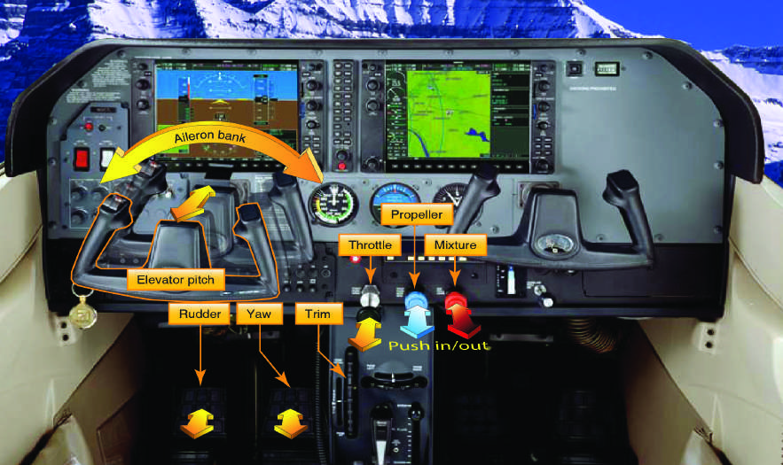
Airplane Flying Handbook (FAA-H-8083-3C)
Chapter 3: Basic Flight Maneuvers
Introduction
Airplanes operate in an environment that is unlike an automobile. Drivers tend to drive with a fairly narrow field of view and focus
primarily on forward motion. Beginning pilots tend to practice the same. Flight instructors face the challenge of teaching beginning
pilots about attitude awareness; which requires understanding the motions of flight. An airplane rotates in bank, pitch, and yaw while
also moving horizontally, vertically, and laterally. The four fundamentals (straight-and-level flight, turns, climbs, and descents) are
the principal maneuvers that control the airplane through the six motions of flight.
The Four Fundamentals
To master any subject, one should first master the fundamentals. For flying, this includes straight-and-level flight, turns, climbs, and
descents. All flying tasks are based on these maneuvers, and an attempt to move on to advanced maneuvers prior to mastering the four
fundamentals hinders the learning process.
Consider the following: a takeoff is a combination of a ground roll, which may transition to a brief period of straight-and-level flight,
and a climb. After
-
departure includes the climb and turns toward the first navigation fix and is followed by straight-and-level flight.
The preparation for landing at the destination may include combinations of descents, turns, and straight-and-level flight. In a typical
general aviation (
GA
)
airplane, the final approach ends with a transition from descent to straight-and-level while slowing for the
touchdown and ground roll.
The flight instructor needs to impart competent knowledge of these basic flight maneuvers so that the beginning pilot is able to
combine them at a performance level that at least meets the Federal Aviation Administration (FAA) Airman Certification Standards
(ACS) or Practical Test Standards (PTS). As the beginning pilot progresses to more complex flight maneuvers, any deficiencies in the
mastery of the four fundamentals are likely to become barriers to effective and efficient learning.
Effect and Use of Flight Controls
The airplane flies in an environment that allows it to travel up and down as well as left and right. Note that movement
up or down
depends on the flight conditions. If the airplane is right-side up relative to the horizon, forward control stick or wheel (elevator
control) movement will result in a loss of altitude. If the same airplane is upside
-
down relative to the horizon that same forward
control movement will result in a gain of altitude.
[Figure 3-1]
The following discussion considers the pilot's frame of reference with
respect to the flight controls.
[Figure 3-2]
Figure 3-1.
Basic flight controls and instrument panel.
3-1
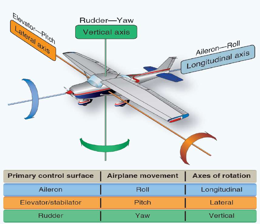
Figure 3-2.
The pilot is always considered the referenced center of effect as the flight controls are used.
With
the pilot’s
hand:
⦁
When pulling the elevator pitch control toward the pilot, which is an aft movement of the control wheel,
yoke,
control stick,
or
side stick
controller
(referred
to
as adding
back
pressure),
the airplane’s
nose will
rotate backwards relative to the pilot around the pitch (lateral) axis of the airplane. Think of this movement
from
the pilot’s
feet to
the pilot’s
head.
⦁
When pushing elevator pitch control toward the instrument panel, (referred to as increasing forward
pressure), the airplane rotates the nose forward relative to the pilot around the pitch axis of the airplane.
Think
of
this
movement from
the pilot’s
head
to
the pilot’s
feet.
⦁
When right pressure is applied to the aileron control, which rotates the control wheel or yoke
clockwise,
or
deflects the control stick
or
side stick
to
the right, the airplane’s
right wing
banks
(rolls)
lower
in
relation
to
the pilot. Think
of
this
movement from
the pilot’s
head
to
the pilot’s
right hip.
⦁
When left pressure is applied to the aileron control, which rotates the control wheel or yoke
counterclockwise,
or
deflects the control stick
or
side stick
to
the left, the airplane’s
left wing
banks
(rolls)
lower
in
relation
to
the pilot. Think
of
this
movement from
the pilot’s
head
to
the pilot’s
left hip.
With
the pilot’s
feet:
⦁
When
forward
pressure is
applied
to
the right rudder
pedal,
the airplane’s
nose moves (yaws)
to
the right in
relation
to
the pilot. Think
of
this
movement from
the pilot’s
left shoulder
to
the pilot’s
right shoulder.
⦁
When
forward
pressure is
applied
to
the left rudder
pedal,
the airplane’s
nose moves (yaws)
to
the left in
relation
to
the pilot. Think
of
this
movement from
the pilot’s
right shoulder
to
the pilot’s
left shoulder.
3-2
While in flight, the control surfaces remain in a fixed position as long as all forces acting upon them remain balanced. Resistance to
movement increases as airspeed increases and decreases as airspeed decreases. Resistance also increases as the controls move away
from a streamlined position. While m
a
ne
u
vering the airplane, it is not the amount of control surface displacement the pilot needs to
consider, but rather the application of flight control pressures that give the desired result.
The pilot should hold the pitch and roll flight controls (aileron and elevator controls, yoke, stick, or side-stick control) lightly with the
fingers and not grab or squeeze them with the entire hand. When flight control pressure is applied to change a control surface
position, the pilot should exert pressure on the aileron and elevator controls with the fingers only. This is an important concept and
habit to learn. A common error with beginning pilots is that they grab the aileron and elevator controls with a closed palm with such
force that sensitive feeling is lost.
Pilots may wish to consider this error at the onset of training as it prevents the development of
“feel,” which is an important aspect of airplane control.
So that slight rudder pressure changes can be felt, both heels should support the weight of the pilot's feet on the floor with the ball of
each foot touching the individual rudder pedals. The legs and feet should be relaxed. When using the rudder pedals, pressure should be
applied smoothly and evenly by pressing with the ball of one foot. Since the rudder pedals are interconnected through springs or a
direct mechanical linkage and act in opposite directions, when pressure is applied to one rudder pedal, foot pressure on the opposite
rudder pedal should be relaxed proportionately.
In summary, during flight, the pressure the pilot exerts on the aileron and elevator controls and rudder pedals causes the airplane to
move about the roll (longitudinal), pitch (lateral), and yaw (vertical) axes. When a control surface moves out of its streamlined
position (even slightly), moving air exerts a force against that surface. It is this force that the pilot feels on the controls.
Feel of the Airplane
The ability to sense a flight condition, such as straight-and-level flight or a dive, without relying on instrumentation is often called
“feeling the airplane.” Examples of this “feel” may be sounds of the airflow across the airframe, vibrations felt through the
controls,
engine and propeller sounds and vibrations at various flight attitudes, and the sensations felt by the pilot through physical
accelerations.
Humans sense “feel” through kinesthesis (the ability to sense movement through the body) and proprioception (unconscious
perception of movement and spatial orientation). These stimuli are detected by nerves and by the semicircular canals of the inner ear.
When properly developed, kinesthesis can provide the pilot with critical information about changes in the airplane’s direction and
speed; however, there are limits in kinesthetic sense when relied upon solely without visual information, as when flying in instrument
meteorological conditions (IMC). Sole reliance on the kinesthetic sense ultimately leads to disorientation and loss of aircraft control.
Developing this “feel” takes time and exposure in a particular airplane. It only comes with dedicated practice at the various
flight
conditions so that a pilot’s senses are trained by the sounds, vibrations, and forces produced by the airplane. The following
are some
important examples:
⦁
Rushing air creates a distinctive noise pattern and as the level of sound increases, it likely indicates that the
airplane’s
airspeed
is
increasing
and
that the pitch
attitude is
decreasing.
As
the noise decreases, the
airplane’s
pitch
attitude is
likely
increasing
and
its
airspeed
decreasing.
⦁
The sound of the engine in cruise flight is different from that in a climb and different again when in a dive.
In fixed-pitch propeller airplanes, when the airplane’s pitch attitude increases, the engine sound
decreases
and as pitch attitude decreases, the engine
sound
increases.
⦁
In a banked turn, the pilot is forced downward into the seat due to the resultant load factor. The increased G
force of a turn feels the same as the pull up from a dive, and the decreased G force from leveling out feels
the same as lowering the nose out of a climb.
Sources
of
actual “feel” are very
important to
the pilot. This
actual feel is
the result of
acceleration,
which
is
simply
how
fast velocity
is changing. Acceleration describes the rate of change in both the magnitude and the direction of velocity. These accelerations impart
forces on the airplane and its occupants during flight. The pilot can sense vertical forces through pressure changes into the seat
or horizontal forces while being pushed from side to side in the seat if the airplane slips or skids. These forces need not be strong,
only perceptible by the pilot
,
to be useful. An accomplished pilot who has excellent “feel” for the airplane is able to detect
even the
smallest accelerations.
The flight instructor should teach the difference between perceiving and reacting to sound, vibrations, and forces versus
merely noticing them. It is this increased understanding that contributes to developing a
"
feel
"
for the airplane. A pilot who develops
a “feel” for the airplane early in flight training is likely to have less difficulty during more advanced training.
3-3
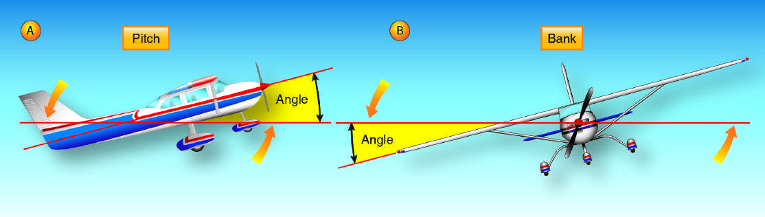
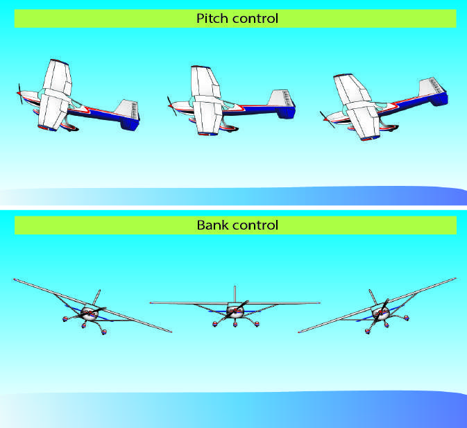
Attitude Flying
An airplane’s attitude is determined by the angular difference between a specific
axis and the natural horizon. A false horizon
can occur when the natural horizon is obscured or not readily apparent. This is an important concept because it requires the pilot to
develop a pictorial sense of this natural horizon. Pitch attitude is the angle formed between the airplane’s longitudinal axis, which
extends from the nose to the tail of the airplane, and the natural horizon. Bank attitude is the angle formed by the airplane’s
lateral axis, which extends from wingtip to wingtip, and the natural horizon.
[Figures 3-3A
and
3-3B]
Angular difference about the
airplane’s
vertical axis
(yaw)
is
an
attitude relative to
the airplane’s
direction
of
flight but not relative to
the natural horizon.
Figure 3-3.
(A)
Pitch
attitude is
the angle formed
between
the airplane’s
longitudinal axis, which
extends
from the nose to
tail of the
airplane, and the natural horizon. (B) Bank attitude is the angle formed by the airplane's lateral axis, which extends from wingtip to
wingtip, and the natural horizon.
Controlling
an
airplane
requires
one
of
two
methods
to
determine
the
airplane’s
attitude
in
reference
to
the
horizon.
When
flying
“visually” in
visual meteorological conditions
(VMC),
a pilot uses their
eyes and
visually
references
the airplane’s
wings
and cowling
to
establish
the airplane’s
attitude to
the natural horizon
(a visible horizon).
If
no
visible horizon
can
be seen
due to
clouds, whiteouts,
haze over the ocean, night over a dark ocean, etc., it is IMC for practical and safety purposes.
[Figure 3-4]
When flying in IMC or
when cross-checking the visual references, the airplane’s attitude is controlled by the pilot referencing the airplane’s mechanical
or electronically
-
generated instruments to determine the airplane’s attitude in relation to the natural horizon.
Figure 3-4.
Airplane attitude is based on relative positions of the nose and wings on the natural horizon.
3-4
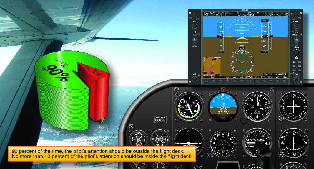
Airplane attitude control is composed of four components: pitch control, bank (roll) control, power control, and trim.
⦁
Pitch control—controlling
of
the airplane’s
pitch
attitude about the lateral axis
by
using
the elevator
to
raise and
lower
the nose in
relation
to
the natural horizon
or
to
the airplane’s
flight instrumentation.
⦁
Bank control—controlling
of
the airplane about the airplane’s
longitudinal axis
by
use of
the ailerons
to
attain
a desired
bank
angle in
relation
to
the natural horizon
or
to
the airplane’s
instrumentation.
⦁
Power control—controlled by the throttle in most general aviation (GA) airplanes and is used when the
flight situation requires a specific thrust setting or for a change in thrust to meet a specific objective.
⦁
Trim control—used to relieve the control pressures held by the pilot on the flight controls after a desired
attitude has been attained.
Note: Yaw control is used to cancel out the effects of yaw
-
induced changes, such as adverse yaw and effects of the propeller.
Integrated Flight Instruction
When introducing basic flight maneuvers to a beginning pilot, it is recommended that the “
i
ntegrated” or “
c
omposite” method of
flight instruction be used. This means the use of outside references and flight instruments to establish and maintain desired
flight attitudes and airplane performance. When beginning pilots use this technique, they achieve a more precise and competent
overall piloting ability. Although this method of airplane control may become second nature with experience, the beginning pilot
needs to make a determined effort to master the technique. In all cases, a pilot’s visual skills need to be sufficiently developed for
long-term, safe, and effective aircraft control.
[Figure 3-5]
Figure 3-5.
Integrated flight instruction teaches pilots to use both external and instrument attitude references.
The basic elements of integrated flight instruction are as follows:
⦁
The pilot visually
controls
the airplane’s
attitude in
reference
outside to
the natural horizon.
Approximately
90
percent of
the pilot’s
attention
should
be devoted
to
outside visual references
and
scanning
for
airborne
traffic. The process of visually evaluating pitch and bank attitude comes from a continuous stream of
attitude information. When the pilot perceives that the attitude is other than desired, the pilot should make
precise, smooth, and accurate flight control corrections to return the airplane to the desired attitude.
Continuous visual checks of the outside references and immediate corrections made by the pilot minimize
the chance for the airplane to deviate from the desired heading, altitude, and flightpath.
3-5
⦁
The airplane’s
attitude is
validated
by
referring
to
flight instruments
and
confirming
performance.
If
the
flight instruments
display
that the airplane’s
performance
is
in
need
of
correction,
the required
correction
needs to be determined and then precisely, smoothly, and accurately applied with reference to the natural
horizon.
The airplane’s
attitude and
performance
are then
rechecked
by
referring
to
flight instruments.
The
pilot then maintains the corrected attitude by reference to the natural horizon.
⦁
The pilot should
monitor
the airplane’s
performance
by
briefly
checking
the flight instruments.
No
more
than
about 10
percent of
the pilot’s
attention
should
be inside the flight deck.
The pilot should
develop
the
skill to quickly analyze the appropriate flight instruments and then immediately return to the visual outside
references
to
control the airplane’s
attitude.
The pilot should become familiar with the relationship between outside visual references to the natural horizon and the corresponding
flight
instrument
indications.
For
example,
a pitch
attitude
adjustment
may
require
a movement
of
the
pilot’s
reference
point
of
several inches in relation to the natural horizon but correspond to a seemingly insignificant movement of the reference bar on the
airplane’s
attitude
indicator.
Similarly,
a deviation
from
a desired
bank
angle,
which
is
obvious
when
referencing
the
airplane’s
wingtips
or
cowling
relative to
the natural horizon,
may
be imperceptible on
the airplane’s
attitude indicator
to
the beginner pilot.
The most common error made by the beginner pilot is to make pitch or bank corrections while still looking inside. It is also common
for beginner pilots to fixate on the flight instruments—a conscious effort is required by them to return to outside visual references.
For the first several hours of instruction, flight instructors may choose to use flight instrument covers to develop a beginning
pilot’s
skill or to correct a pilot’s poor habit of fixating on instruments by forcing them to use outside visual references for aircraft control.
The beginning pilot, not being familiar with the intricacies of flight by references to instruments, including such things as instrument
lag and gyroscopic precession, will invariably make excessive attitude corrections and end up “chasing the instruments.” Airplane
attitude by reference to the natural horizon, however, presents immediate and accurate indications many times larger than on any
instrument. The beginning pilot should understand that anytime airplane attitude by reference to the natural horizon cannot be
established or maintained, the situation has become a genuine emergency and that the use of integrated flight instruction does not
prepare pilots for flight in IMC.
Straight-and-Level Flight
Straight-and-level flight is flight in which heading and altitude are maintained. The other fundamentals are derived as variations from
straight-and-level flight, and the need to form proper and effective skills in flying straight and level should be understood. The ability
to perform straight-and-level flight results from repetition and practice. A high level of skill results when the pilot perceives outside
references, takes mental snap shots of the flight instruments, and makes effective, timely, and proportional corrections from
unintentional slight turns, descents, and climbs.
Straight-and-level flight is a matter of consciously fixing the relationship of a reference point on the airplane in relation to the natural
horizon.
[Figure 3-6]
The establishment of these reference points should be initiated on the ground as they depend on the pilot’s
seating position, height, and posture. The pilot should sit in a normal manner with the seat position adjusted, such that the pilot sees
adequately over the instrument panel while being able to fully depress the rudder pedals without straining or reaching.
A flight instructor may use a dry erase marker or removable tape to make reference lines on the windshield or cowling to help the
beginner pilot establish visual reference points. Vertical reference lines are best established on the ground, such as when the airplane is
placed on a marked centerline, with the beginner pilot seated in proper position. Horizontal reference lines are best established with the
airplane in flight, such as during slow flight and cruise configurations. The horizon reference point is always the same, no matter what
altitude, since the point is always on the horizon, although the distance to the horizon will be further as altitude increases. There are
multiple horizontal reference lines due to varying pitch attitude requirements; however, these teaching aids are generally needed for
only a short period until the beginning pilot understands where and when to look while maneuvering
the airplane.
Straight Flight
Maintaining a constant direction or heading is accomplished by visually checking the relationship of the airplane’s wingtips to the
natural horizon. Depending on whether the airplane is a high wing or low wing, both wingtips should be level and equally above or
below the natural horizon. Any necessary bank corrections are made with the pilot’s coordinated use of ailerons and rudder.
[Figure
3-7]
The pilot should understand that anytime the wings are banked, the airplane turns. The objective of straight flight is to detect and
correct small deviations, necessitating minor flight control corrections. The bank attitude information can also be obtained from a
quick scan of the attitude indicator (which shows the position of the airplane’s wings relative to the horizon) and the heading indicator
(which indicates if the airplane is off the desired heading).
3-6
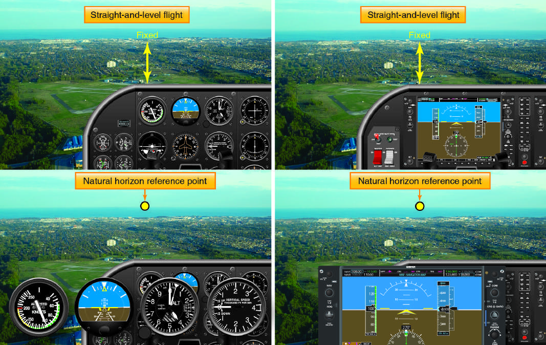
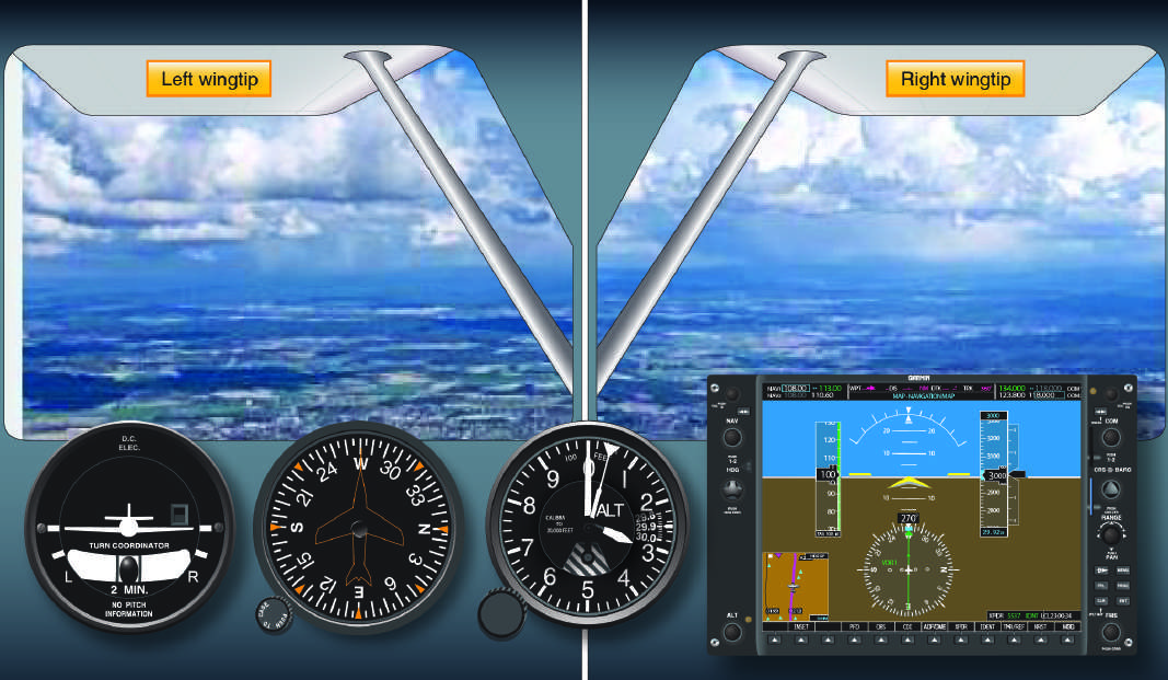
Figure 3-6.
Nose reference for straight-and-level flight.
Figure 3-7.
Wingtip reference for straight-and-level flight.
3-7
It is possible to maintain straight flight by simply exerting the necessary pressure with the ailerons or rudder independently in the
desired direction of correction. However, the practice of using the ailerons and rudder independently is not correct and makes precise
control of the airplane difficult. The correct bank flight control movement requires the coordinated use of ailerons and rudder.
Straight-and-level flight requires almost no application of flight control pressures if the airplane is properly trimmed and the air is
smooth. For that reason, the pilot should not form the habit of unnecessarily moving the flight controls. The pilot needs to learn to
recognize when corrections are necessary and then to make a measured flight control response precisely, smoothly, and accurately.
Pilots
may
tend
to
look
out to
one side continually,
generally
to
the left due to
the pilot’s
left seat position
and
consequently focus
attention in that direction. This not only gives a restricted angle from which the pilot is to observe but also causes the pilot to exert
unconscious pressure on the flight controls in that direction. It is also important that the pilot not fixate in any one direction and
continually
scan
outside the airplane,
not only
to
ensure that the airplane’s
attitude is
correct, but also
to
ensure that the pilot is
considering other factors for safe flight. Continually observing both wingtips has advantages other than being the only positive check
for leveling the wings. This includes looking for aircraft traffic, terrain and weather influences, and maintaining overall situational
awareness.
Straight flight allows flying along a line. For outside references, the pilot selects a point on the horizon aligned with another point
ahead. If those two points stay in alignment, the airplane will track the line formed by the two points. A pilot can also hold a course in
VFR by tracking to a point in front of a compass or magnetic direction indicator, with only glances at the instrument or indicator to
ensure being on course. The reliance on a surface point does not work when flying over water or flat snow covered surfaces. In these
conditions, the pilot should rely on the magnetic heading indication.
Level Flight
In learning to control the airplane in level flight, it is important that the pilot be taught to maintain a light touch on the flight controls
using fingers rather than the common problem of a tight-fisted palm wrapped around the flight controls. The pilot should exert only
enough pressure on the flight controls to produce the desired result. The pilot should learn to associate the apparent movement of the
references with the control pressures which produce attitude movement. As a result, the pilot can develop the ability to adjust the
change desired
in
the airplane’s
attitude by
the amount and
direction
of
pressures applied
to
the flight controls
without the
pilot
excessively referring to instrument or outside references for each minor correction.
The pitch attitude for level flight is first obtained by the pilot being properly seated, selecting a point toward the airplane’s
nose as a
reference, and then keeping that reference point in a fixed position relative to the natural horizon.
[Figure 3-8]
The principles of
attitude flying require that the reference point to the natural horizon position should be cross-checked against the flight instruments to
determine if the pitch attitude is correct. If trending away from the desired altitude, the pitch attitude should be readjusted in relation
to the natural horizon and then the flight instruments crosschecked to determine if altitude is now being corrected or maintained. In
level flight maneuvers,
the terms
“increase the back
pressure”
or
“increase pitch
attitude”
implies
raising
the airplane’s
nose in
relation
to
the natural horizon
and
the terms
“decreasing
the pitch
attitude”
or
“decrease pitch
attitude”
means
lowering
the
nose in
relation
to
the natural horizon.
The pilot’s
primary
reference
is
the natural horizon.
For
all practical purposes, the airplane’s
airspeed
remains
constant in
straight-and-level flight if the power setting is also constant.
Intentional airspeed changes, by increasing or decreasing the engine power, provide proficiency in maintaining straight-and-level
flight as the airplane’s
airspeed
is
changing.
Pitching
moments
may
also
be generated
by
extension
and
retraction
of
flaps,
landing
gear, and other drag producing devices, such as spoilers. Exposure to the effect of the various configurations should be covered in any
specific airplane checkout.
Common Errors
A
common
error
of
a beginner
pilot is
attempting
to
hold
the wings
level by
only
observing
the airplane’s
nose.
Using
this
method,
the nose’s
short horizontal reference
line can
cause slight deviations
to
go
unnoticed.
However,
deviations
from
level flight
are easily
recognizable when
the pilot references
the wingtips
and,
as a result, the wingtips
should
be the pilot’s
primary
reference
for
maintaining level bank attitude. This technique also helps eliminate the potential for flying the airplane with one wing low and
correcting heading errors with the pilot holding opposite rudder pressure. A pilot with a bad habit of dragging one wing low and
compensating with opposite rudder pressure will have difficulty mastering other flight maneuvers.
3-8
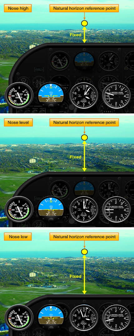
Figure 3-8.
Nose reference for level flight.
Common errors include:
1. Attempting to use improper pitch and bank refeequent flights.
2. Forgetting the location of preselected reference points on subsequent flights.
3. Attempting to establish or correct airplane attitude using flight instruments rather than the natural horizon.
4. “Chasing” the flight instruments
rather
than
adhering
to
the principles of
attitude flying.
5. Mechanically pushing or pulling on the flight controls rather than exerting accurate and smooth pressure.
6. Not scanning outside the aircraft for other traffic and weather and terrain influences.
7. A tight palm grip on the flight controls resulting in a desensitized feeling of the hand and fingers.
8. Overcontrolling the airplane.
9. Habitually flying with one wing low or maintaining directional control using only the rudder control.
10. Failure to make timely and measured control inputs after a deviation from straight-and-level.
11. Inadequate attention to sensory inputs in developing feel for trence points on the airplane to establish attitude.
3-9
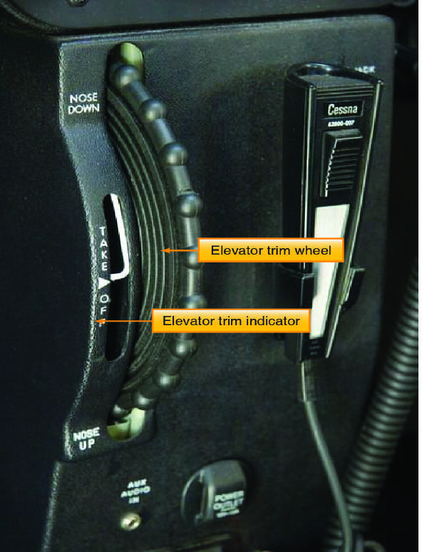
Trim Control
Trim control surfaces are required to offset any constant flight control pressure inputs provided by the pilot. For example, elevator
trim is a typical trim in light GA airplanes and is used to null the pressure exerted by the pilot in order to maintain a particular pitch
attitude.
[Figure 3-9]
This provides an opportunity for the pilot to divert attention to other tasks.
Figure 3-9.
Elevator trim is used in airplanes to null the pressure exerted by the pilot on the pitch flight control.
Because of their relatively low power, speed, and cost constraints, not all light airplanes have a complete set (elevator, rudder, and
aileron) of trim controls that are adjustable from inside the flight deck. Nearly all light airplanes are equipped with at least adjustable
elevator trim. As airplanes increase in power, weight, and complexity, flight deck adjustable trim systems for the rudder and aileron
may be available.
In airplanes where multiple trim axes are available, the rudder should be trimmed first. Rudder, elevator, and then aileron should be
trimmed next in sequence. However, if the airspeed is varying, continuous attempts to trim the rudder and aileron produce
unnecessary pilot workload and distraction. Attempts to trim the rudder at varying airspeeds are impractical in many propeller
airplanes because of the built-in
compensation
for
the effect of
a propeller’s
left turning
tendencies. The correct procedure is
when
the
pilot has established a constant airspeed and pitch attitude, the pilot should then hold the wings level with aileron flight control
pressure while rudder control pressure is trimmed out. Finally, aileron trim should be adjusted to relieve any aileron flight control
pressure.
A properly trimmed airplane is an indication of good piloting skills. Any control forces that the pilot feels should be a result of
deliberate flight control pressure inputs during a planned change in airplane attitude, not a result of forces being applied by the
airplane. A common trim control error is the tendency for the pilot to overcontrol the airplane with trim adjustments. Attempting to
fly the airplane with the trim is a common fault in basic flying technique even among experienced pilots. The airplane attitude should
be established first and held with the appropriate flight control pressures, and then the flight control pressures trimmed out so that the
airplane maintains the desired attitude without the pilot exerting flight control pressure.
3-10
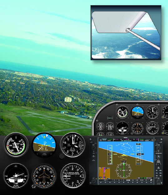
Level Turns
A
turn
is
initiated
by
banking
the wings
in
the desired
direction
of
the turn
through
the pilot’s
use of
the aileron
flight controls. Left
aileron flight control pressure causes the left wing to lower in relation to the pilot. Right aileron flight control pressure causes the
right wing to lower in relation to the pilot. In other words, to turn left, the pilot lowers the left wing with aileron by left stick. To turn
right, the pilot lowers the right wing with right stick. Depending on bank angle and airplane engineering, at many bank angles, the
airplane will continue to turn with ailerons neutralized. The sequence could be as follows:
1.
Bank the airplane, adding either enough power or pitching up to compensate for the loss of vertical lift.
2.
Neutralize controls as necessary to stop bank from increasing and hold desired bank angle.
3.
Use the opposite stick (aileron) to return airplane to level.
4.
Neutralize the ailerons (along with either power or pitch reduction) for level flight.
[Figure 3-10]
Figure 3-10.
Level turn to the left.
A turn is the result of the following:
⦁
The ailerons bank the wings and determine the rate of turn for a given airspeed. Lift is divided into both
vertical and horizontal lift components as a result of the bank. The horizontal component of lift moves the
airplane toward the banked direction.
⦁
The elevator pitches the nose of the airplane up or down in relation to the pilot and perpendicular to the
wings. If the pilot does not add power, and there is sufficient airspeed margin, the pilot needs to slightly
increase the pitch to increase wing lift enough to replace the wing lift being diverted into turning force so
as to maintain the current altitude.
⦁
The vertical fin on an airplane does not produce lift. Rather the vertical fin on an airplane is a stabilizing
surface and
produces
no
lift if
the airplane is
flying
straight ahead.
The vertical fin’s
purpose is
to
keep
the
aft end of the airplane behind the front end.
⦁
The throttle provides thrust, which may be used for airspeed control and to vary the radius of the turn.
⦁
The pilot uses the rudder
to
offset any
adverse yaw
developed
by
wing’s
differential lift and
the
engine/propeller. The rudder does not turn the airplane. The rudder is used to maintain coordinated flight.
3-11
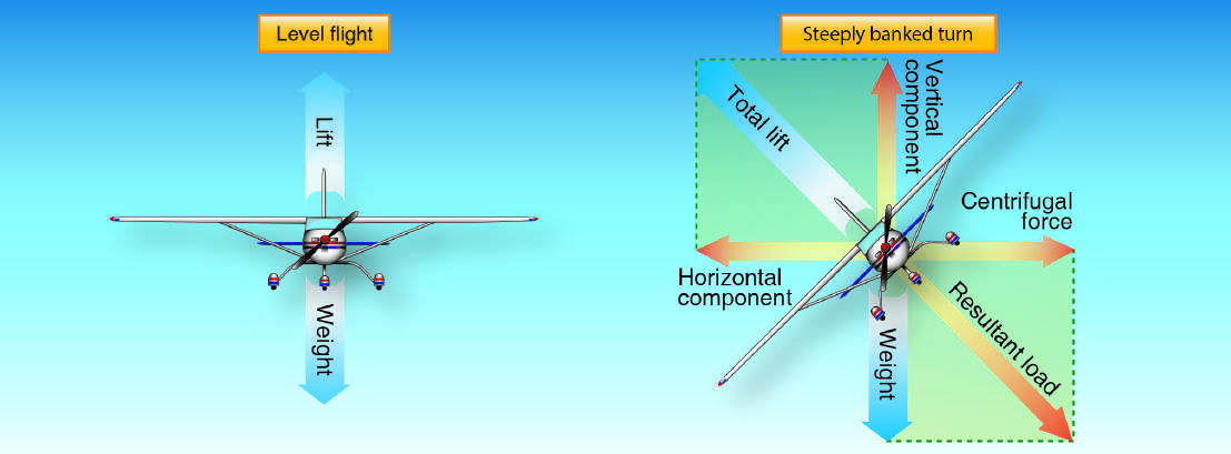
For purposes of this discussion, turns are divided into three classes: shallow, medium, and steep.
⦁
Shallow turns—bank angle is approximately 20° or
less.
This
shallow
bank
is
such
that the inherent lateral
stability of the airplane slowly levels the wings unless aileron pressure in the desired direction of bank is
held by the pilot to maintain the bank angle.
⦁
Medium turns—result from a degree of bank between approximately 20°
and
45°. At medium bank angles,
the airplane’s
inherent lateral stability
does not return
the wings
to
level flight. As
a result, the airplane
tends to remain at a constant bank angle without any flight control pressure held by the pilot. The pilot
neutralizes the aileron flight control pressure to maintain the bank.
⦁
Steep turns—result from a degree of bank of approximately 45° or
more.
The airplane continues in
the
direction of the bank even with neutral flight controls unless the pilot provides opposite flight control
aileron pressure to prevent the airplane from overbanking. The actual amount of opposite flight control
pressure used depends on various factors, such as bank angle and airspeed.
When an airplane is flying straight and level, the total lift is acting perpendicular to the wings and to the
e
arth. As the airplane is
banked into a turn, total lift is the resultant of two components: vertical and horizontal.
[Figure 3-11]
The vertical lift component
continues to act perpendicular to the
e
arth and opposes gravity. The horizontal lift component acts parallel to the
e
arth’s surface
opposing centrifugal force. These two lift components act at right angles to each other, causing the resultant total lifting force to act
perpendicular to the banked wing of the airplane. It is the horizontal lift component that begins to turn the airplane and not the rudder.
Figure 3-11
.
When the airplane is banked into a turn, total lift is the resultant of two components: vertical and horizontal.
In constant altitude, constant airspeed turns, it is necessary to increase the AOA of the wing when rolling into the turn by increasing
back pressure on the elevator, as well to add power countering the loss of speed due to increased drag. This is required because total
lift has divided into vertical and horizontal components of lift. In order to maintain altitude, the total lift (since total lift acts
perpendicular to the wing) needs to be increased to meet the vertical component of lift requirements (to balance weight and load
factor) for level flight.
The purpose of the rudder in a turn is to coordinate the turn. As lift increases, so does drag. When the pilot deflects the ailerons to
bank the airplane, both lift and drag are increased on the rising wing and, simultaneously, lift and drag are decreased on the lowering
wing.
[Figure 3-12]
This increased drag on the rising wing and decreased drag on the lowering wing results in the airplane yawing
opposite to the direction of turn. To counteract this adverse yaw, rudder pressure is applied simultaneously with the aileron deflection
in the desired direction of turn. This action is required to produce a coordinated turn. Coordinated flight is an important part of
airplane control. Situations can develop when a pilot maintains certain uncoordinated flight control deflections, which create the
potential for a spin. This is especially hazardous when operating at low altitudes, such as when operating in the airport traffic pattern.
3-12
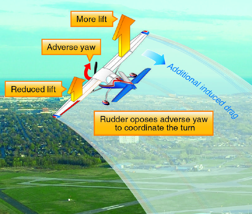
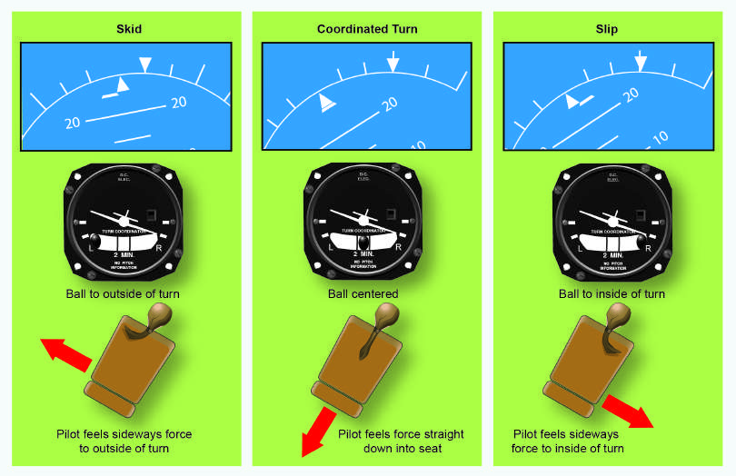
Figure 3-12.
The rudder opposes adverse yaw to help coordinate the turn.
During uncoordinated flight, the pilot may feel that they are being pushed sideways toward the outside or inside of the turn.
[Figure
3-13]
The pilot feels pressed toward the outside of a turn during a skid and feels pressed toward the inside of a turn during a slip. The
ability
to
sense a skid
or
slip
is
developed
over
time and
as the “feel” of
flying
develops,
a pilot should
become highly
sensitive to a
slip or skid without undue reliance on the flight instruments.
Figure 3-13.
Indications of a slip and skid.
3-13
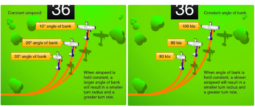
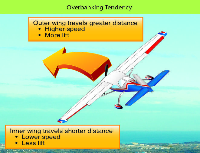
Turn Radius
To understand the relationship between airspeed, bank, and radius of turn, it should be noted that the rate of turn at any given true
airspeed depends on the horizontal lift component. The horizontal lift component varies in proportion to the amount of bank.
Therefore, the rate of turn at a given airspeed increases as the angle of bank is increased. On the other hand, when a turn is made at a
higher airspeed at a given bank angle, the inertia is greater and the horizontal lift component required for the turn is greater, causing
the turning rate to become slower.
[Figure 3-14]
Therefore, at a given angle of bank, a higher airspeed makes the radius of turn larger
because the airplane turns at a slower rate.
Figure 3-14.
Angle of bank and airspeed regulate rate and radius of turn.
As the radius of the turn becomes smaller, a significant difference develops between the airspeed of the inside wing and the airspeed
of the outside wing. The wing on the outside of the turn travels a longer path than the inside wing, yet both complete their respective
paths in the same unit of time.
Therefore, the outside wing travels at a faster airspeed than the inside wing and, as a result, it develops more lift. This creates
an overbanking tendency that needs to be controlled by the use of opposite aileron when the desired bank angle is reached.
[Figure
3-15]
Because the outboard wing is developing more lift, it also produces more drag. The drag causes a slight slip during steep turns
that should be corrected by use of the rudder.
Figure 3-15.
Overbanking tendency.
3-14
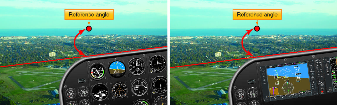
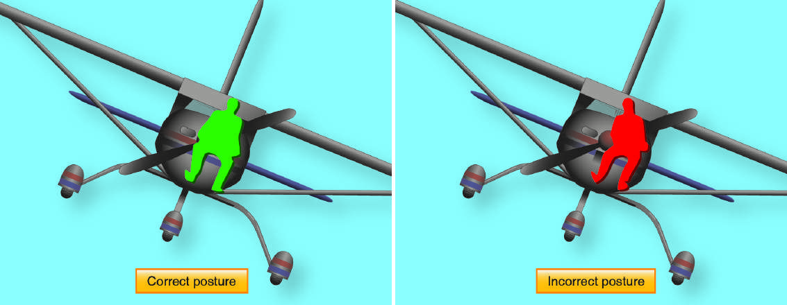
Establishing a Turn
On most light single-engine airplanes, the top surface of the engine cowling is fairly flat, and its horizontal surface to the natural
horizon provides a reasonable indication for initially setting the degree of bank angle.
[Figure 3-16]
The pilot should then cross-
check the flight instruments to verify that the correct bank angle has been achieved. Information obtained from the attitude indicator
shows the angle of the wing in relation to the horizon.
Figure 3-16.
Visual reference for angle of bank.
The pilot’s seating position in the airplane is important as it affects the interpretation of outside visual references. A common
problem is that a pilot may lean away from the turn in an attempt to remain in an upright position in relation to the horizon.
This should be corrected immediately if the pilot is to properly learn to use visual references.
[Figure 3-17]
Figure 3-17.
Correct and incorrect posture while seated in the airplane.
Because most airplanes have side-by-side seating,
a pilot does not sit on
the airplane’s
longitudinal axis,
which
is
where the airplane
rotates in roll. The pilot sits slightly off to one side, typically the left, of the longitudinal axis. Due to parallax error, this makes the
nose of the airplane appear to rise when making a left turn (due to pilot lowering in relation to the longitudinal axis) and the nose of
the airplane appear to descend when making right turns (due to pilot elevating in relation to the longitudinal axis).
[Figure 3-18]
Beginning pilots should not use large aileron and rudder control inputs. This is because large control inputs produce rapid roll rates
and allow little time for the pilot to evaluate and make corrections. Smaller flight control inputs result in slower roll rates and provide
for more time to accurately complete the necessary pitch and bank corrections.
3-15
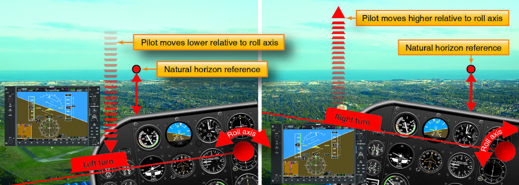
Figure 3-18.
Parallax view.
Some additional considerations for initiating turns are the following:
⦁
If
the airplane’s
nose starts
to
move before the bank
starts,
the rudder
is
being
applied
too
soon.
⦁
If the bank starts before the nose starts turning or the nose moves in the opposite direction, the rudder is
being applied too late.
⦁
If the nose moves up or down when entering a bank, excessive or insufficient elevator back pressure is
being applied.
After the bank has been established, all flight control pressures applied to the ailerons and rudder may be relaxed or adjusted,
depending on the established bank angle, to compensate for the airplane’s inherent stability or overbanking tendencies. The airplane
should remain at the desired bank angle with the proper application of aileron pressure. If the desired bank angle is shallow, the pilot
needs to maintain a small amount of aileron pressure into the direction of bank including rudder to compensate for yaw effects. For
medium bank angles, the ailerons and rudder should be neutralized. Steep bank angles require opposite aileron and rudder to prevent
the bank from steepening.
Back pressure on the elevator should not be relaxed as the vertical component of lift should be maintained if altitude is to be
maintained. Throughout the turn, the pilot should reference the natural horizon, scan for aircraft traffic, and occasionally crosscheck
the flight instruments to verify performance. A reduction in airspeed is the result of increased drag but is generally not significant for
shallow bank angles. In steeper turns, additional power may be required to maintain airspeed. If altitude is not being maintained
during the turn, the pitch attitude should be corrected in relation to the natural horizon and cross-checked with the flight instruments
to verify performance.
Steep turns require accurate, smooth, and timely flight control inputs. Minor corrections for pitch attitude are accomplished with
proportional elevator back pressure while the bank angle is held constant with the ailerons. However, during steep turns, it is not
uncommon for a pilot to allow the nose to get excessively low resulting in a significant loss in altitude in a very short period of time.
The recovery sequence requires that the pilot first reduce the angle of bank with coordinated use of opposite aileron and rudder and
then increase the pitch attitude by increasing elevator back pressure. If recovery from an excessively nose-low, steep bank condition
is attempted by use of the elevator only, it only causes a steepening of the bank and unnecessary stress on the airplane. Steep turn
performance can be improved by an appropriate application of power to overcome the increase in drag. Depending on the purpose of
a steep turn and the magnitude of control force needed, trimming additional elevator back pressure as the bank angle goes beyond 30°
may assist the pilot during the turn.
Since the airplane continues turning as long as there is any bank, the rollout from the turn should be started before reaching the
desired heading. The amount of lead required to rollout on the desired heading depends on the degree of bank used in the turn. A rule
of thumb is to lead by one-half the angle of bank. For example, if the bank is 30°, lead the rollout by 15°. The rollout from a turn is
similar to the roll-in except the flight controls are applied in the opposite direction. Aileron and rudder are applied in the direction of
the rollout or toward the high wing. As the angle of bank decreases, the elevator pressure should be relaxed as necessary to maintain
altitude. As the wings become level, the flight control pressures should be smoothly relaxed so that the controls are neutralized as the
airplane returns to straight-and-level flight. If trim was used, such as during a steep turn, forward elevator pressure may be required
until the trim can be adjusted. As the rollout is being completed, attention should be given to outside visual references, as well as the
flight instruments to determine that the wings are being leveled and the turn stopped.
3-16
Because the elevator and ailerons are on one control, practice is required to ensure that only the intended pressure is applied to the
intended flight control. For example, a beginner pilot is likely to unintentionally add pressure to the pitch control when the only bank
was intended. This cross-coupling may be diminished or enhanced by the design of the flight controls; however, practice is the
appropriate measure for smooth, precise, and accurate flight control inputs. For example, diving when turning right and climbing
when turning left in airplanes is common with stick controls, because the arm tends to rotate from the elbow joint, which induces a
secondary arc control motion if the pilot is not extremely careful. Likewise, lowering the nose is likely to induce a right turn, and
raising the nose to climb tends to induce a left turn. These actions would apply for a pilot using the right hand to move the stick.
Airplanes with a control wheel may be less prone to these inadvertent actions, depending on control positions and pilot seating. In any
case, the pilot should retain the proper sight picture of the nose following the horizon, whether up, down, left
,
or right and
isolate undesired motion.
Common errors in level turns are:
1. Failure to adequately clear in the direction of turn for aircraft traffic.
2. Gaining or losing altitude during the turn.
3. Not holding the desired bank angle constant.
4. Attempting to execute the turn solely by instrument reference.
5. Leaning away from the direction of the turn while seated.
6. Insufficient feel for the airplane as evidenced by the inability to detect slips or skids without flight instruments.
7. Attempting
to
maintain
a constant bank
angle by
referencing
only
the airplane’s
nose.
8. Making skidding flat turns to avoid banking the airplane.
9. Holding excessive rudder in the direction of turn.
10. Gaining proficiency in turns in only one direction.
11. Failure to coordinate the controls.
Climbs and Climbing Turns
When an airplane enters a climb, excess lift needs to be developed to overcome the weight or gravity. This requirement to develop
more lift results in more induced drag, which either results in decreased airspeed or an increased power setting to maintain a
minimum airspeed in the climb. An airplane can only sustain a climb when there is sufficient thrust to offset increased drag; therefore,
climb rate is limited by the excess thrust available.
The pilot should know the engine power settings, natural horizon pitch attitudes, and flight instrument indications that produce the
following types of climb:
⦁
Normal climb—performed at an airspeed recommended by the airplane manufacturer. Normal climb speed
is
generally
higher
than
the airplane’s
best rate of
climb.
The additional airspeed
provides for
better
engine
cooling, greater control authority, and better visibility over the nose of the airplane. Normal climb is
sometimes referred to as cruise climb.
⦁
Best rate of climb (V
Y
)—produces the most altitude gained over a given amount of time. This airspeed is
typically used when initially departing a runway without obstructions until it is safe to transition to a normal
or cruise climb configuration.
⦁
Best angle of climb (V
X
)—performed at an airspeed that produces the most altitude gain over a given
horizontal distance. The best angle of climb results in a steeper climb, although the airplane takes more
time to reach the same altitude than it would at best rate of climb airspeed. The best angle of climb is used
to clear obstacles, such as a strand of trees, after takeoff.
[Figure 3-19]
It should be noted that as altitude increases, the airspeed for best angle of climb increases and the airspeed for best rate of climb
decreases. Performance
charts
contained
in
the Airplane Flight Manual or
Pilot’s
Operating
Handbook
(AFM/POH)
should
be
consulted to ensure that the correct airspeed is used for the desired climb profile at the given environmental conditions. There is a
point at which the best angle of climb airspeed and the best rate of climb airspeed intersect. This occurs at the absolute ceiling at
which the airplane is incapable of climbing any higher.
[Figure 3-20]
3-17
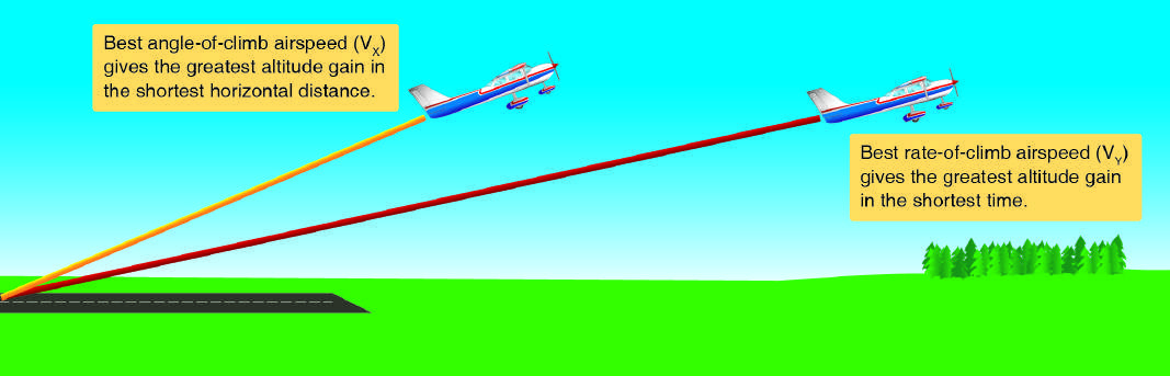
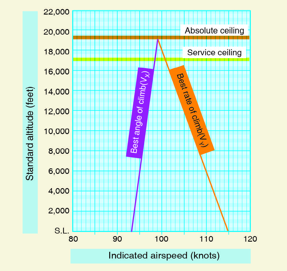
Figure 3-19.
Best angle of climb verses best rate of climb.
Figure 3-20.
Absolute ceiling.
3-18
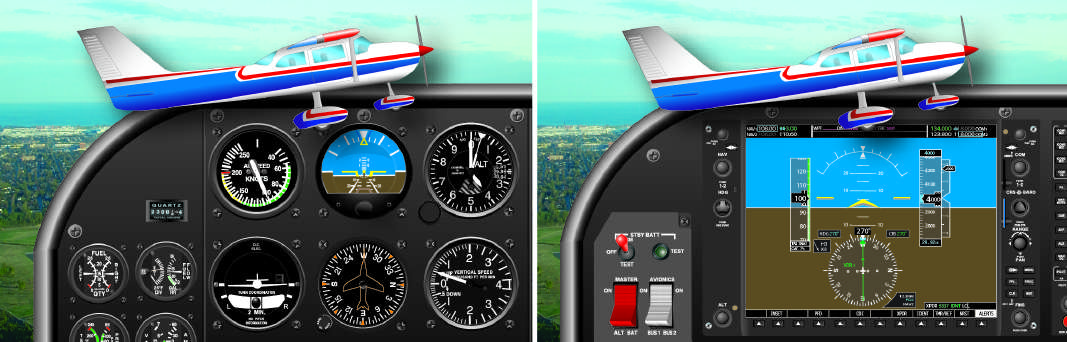
Establishing a Climb
A straight climb is entered by gently increasing back pressure on the elevator flight control to the pitch attitude referencing the
airplane’s
nose to
the natural horizon
while simultaneously
increasing
engine power
to
the climb
power
setting.
The wingtips
should
be referenced in maintaining the climb attitude while cross-checking the flight instruments to verify performance. In many airplanes,
as power
is
increased,
an
increase in
slipstream
over
the horizontal stabilizer
causes the airplane’s
pitch
attitude to
increase more than
desired. The pilot should be prepared for slipstream effects but also for the effect of changing airspeed and changes in lift. The pilot
should be prepared to use the required flight control pressures to achieve the desired pitch attitude.
If a climb is started from cruise flight, the airspeed gradually decreases as the airplane enters a stabilized climb attitude. The thrust
required to maintain straight-and-level flight at a given airspeed is not sufficient to maintain the same airspeed in a climb. Increase
drag in a climb stems from increased lift demands made upon the wing to increase altitude. Climbing requires an excess of lift over
that necessary to maintain level flight. Increased lift will generate more induced drag. That increase in induced drag is why more
power is needed and why a sustained climb requires an excess of thrust.
For practical purposes gravity or weight is a constant. A vector diagram shows why more lift is necessary during a climb, as the
vertical component of lift generated from the wings is no longer perpendicular to the wings and adds to drag. The total vertical force
is increased by adding a vertical component of thrust from the powerplant, and the power should be advanced to the recommended
climb power. On airplanes equipped with an independently controllable-pitch propeller, this requires advancing the propeller control
prior to increasing engine power. Some airplanes may be equipped with cowl flaps to facilitate effective engine cooling. The position
of
the cowl flaps
should
be set to
ensure cylinder
head
temperatures remain
within
the manufacturer’s
specifications.
Engines that are normally aspirated experience a reduction of power as altitude is gained. As altitude increases, air density decreases,
which results in a reduction of power. The indications show a reduction in revolutions per minute (rpm) for airplanes with fixed pitch
propellers; airplanes that are equipped with controllable propellers show a decrease in manifold pressure. The pilot should reference
the engine instruments to ensure that climb power is being maintained and that pressures and temperatures are within the
manufacturer’s
limits.
As
power
decreases
in
the
climb,
the
pilot
continually
advances
the
throttle
or
power
lever
to
maintain
specified climb settings.
The pilot should understand propeller effects during a climb and when using high power settings
. The propeller in most airplanes
rotates clockwise when seen from the pilot’s position. As pitch attitude is increased, the center of thrust from the propeller moves to
the right and becomes asymmetrical. This asymmetric condition is often called “P-factor.” This is the result of the increased AOA of
the descending propeller blade, which is the right side of the propeller disc when seen from the flight deck. As the center of propeller
thrust moves to the right, a left turning yawing moment moves the nose of the airplane to the left. This is compensated by the pilot
through right rudder pressure. In addition, torque that acts opposite to the direction of propeller rotation causes the airplane to roll to
the left. Under these conditions, torque and P-factor cause the airplane to roll and yaw to the left. To counteract this, right rudder and
aileron flight control pressures should be used. During the initial practice of climbs, this may initially seem awkward; however, after
some experience the correction for propeller effects becomes instinctive.
As the airspeed decreases during the climb’s establishment, the airplane’s pitch attitude tends to lower unless the pilot increases the
elevator flight control pressure. Nose-up elevator trim should be used so that the pitch attitude can be maintained without the pilot
holding back elevator pressure. Throughout the climb, since the power should be fixed at the climb power setting, airspeed is
controlled by the use of elevator pressure. The pitch attitude to the natural horizon determines if the pitch attitude is correct and
should be cross-checked to the flight instruments to verify climb performance.
[Figure 3-21]
Figure 3-21.
Climb indications.
3-19
To return to straight-and-level flight from a climb, it is necessary to begin leveling-off prior to reaching the desired altitude. Level-off
should begin at approximately 10 percent of the rate of climb. For example, if the airplane is climbing at 500 feet per minute (fpm),
leveling off should begin 50 feet prior to reaching the desired altitude. The pitch attitude should be decreased smoothly and slowly to
allow for the airspeed to increase. A loss of altitude may result if the pitch attitude is changed too rapidly without allowing the
airspeed to increase proportionately.
After the airplane is established in level flight at a constant altitude, climb power should be retained temporarily so that the airplane
accelerates to the cruise airspeed. When the airspeed reaches the desired cruise airspeed, the throttle setting and the propeller control,
if equipped, should be set to the cruise power setting and the airplane re-trimmed.
Climbing Turns
In the performance of climbing turns, the following factors should be considered:
⦁
With a constant power setting, the same pitch attitude and airspeed cannot be maintained in a bank as in a
straight climb due to the increase in the total lift required. The airplane climbs at a slightly shallower climb
angle because some of the lift is being used to turn the airplane.
⦁
Steep bank angles significantly decreases the rate of climb. The pilot should establish and maintain an
appropriate constant bank during the turn.
⦁
The pilot should maintain a constant airspeed and constant rate of turn in both right and left turns. The
coordination of all flight controls is a primary factor.
All the factors that affect the airplane during level constant-altitude turns affect the airplane during climbing turns. Compensation for
the inherent stability of the airplane, overbanking tendencies, adverse yaw, propeller effects, reduction of the vertical component of
lift, and increased drag needs to be managed by the pilot through the manipulation of the flight controls.
Climbing turns may be established by entering the climb first and then banking into the turn or climbing and turning simultaneously.
During climbing turns, as in any turn, the loss of vertical lift should be compensated by an increase in pitch attitude. When a turn is
coupled with a climb, the additional drag and reduction in the vertical component of lift need to be further compensated for by an
additional increase in elevator back pressure. When turns are simultaneous with a climb, it is most effective to limit the turns to
shallow bank angles. This provides for an efficient rate of climb. If a medium or steep banked turn is used, climb performance is
degraded or possibly non-existent.
Common errors in the performance of climbs and climbing turns are:
1. Attempting to establish climb pitch attitude by primarily referencing the airspeed indicator and chasing the airspeed.
2. Applying elevator pressure too aggressively resulting in an excessive climb angle.
3. Inadequate or inappropriate rudder pressure during climbing turns.
4. Allowing the airplane to yaw during climbs usually due to inadequate right rudder pressure.
5. Fixation
on
the airplane’s
nose during
straight climbs,
resulting
in
climbing
with
one wing
low.
6. Initiating a climbing turn without coordinated use of flight controls, resulting in no turn and a climb with one wing low.
7. Improper coordination resulting in a slip that counteracts the rate of climb, resulting in little or no altitude gain.
8. Inability to keep pitch and bank attitude constant during climbing turns.
9. Attempting
to
exceed
the airplane’s
climb
capability.
10. Using excessive forward elevator pressure during level-off resulting in a loss of altitude or excessive low G-force.
Descents and Descending Turns
When an airplane enters a descent, its attitude changes from level flight to flight with a descent profile.
[Figure 3-22]
In a descent,
weight no longer acts solely perpendicular to the flightpath. Since induced drag is decreased as lift is reduced in order to descend,
excess thrust will provide higher airspeeds. The weight/gravity force is about the same. This causes an increase in total thrust and a
power reduction is required to balance the forces if airspeed is to be maintained.
3-20
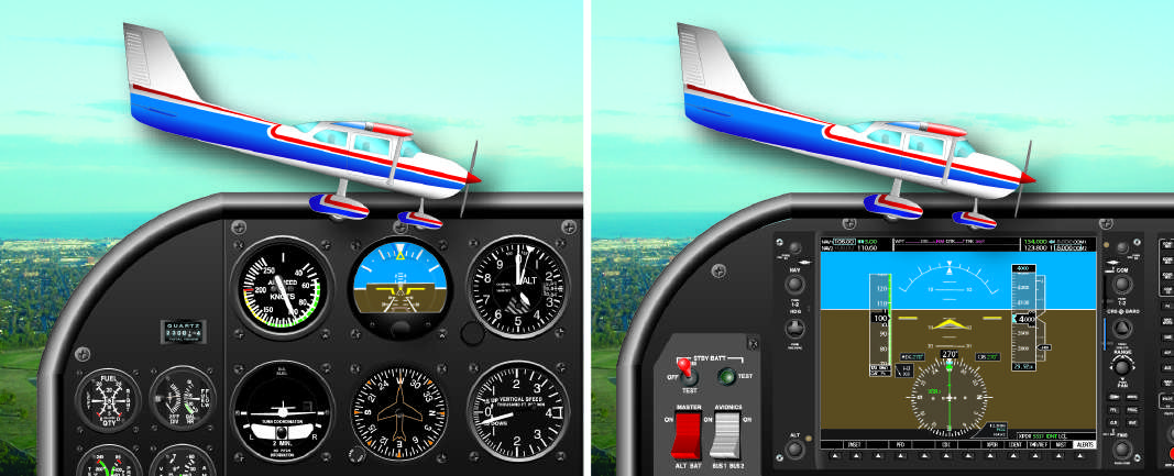
Figure 3-22.
Descent indications.
The pilot should know the engine power settings, natural horizon pitch attitudes, and flight instrument indications that produce the
following types of descents:
⦁
Partial power descent—the normal method of losing altitude is to descend with partial power. This is often
termed cruise or en route descent. The airspeed and power setting recommended by the AFM/POH for
prolonged descent should be used. The target descent rate should be 500 fpm. The desired airspeed, pitch
attitude, and power combination should be preselected and kept constant.
⦁
Descent at minimum safe airspeed—a nose-high, power-assisted descent condition principally used
for clearing obstacles during a landing approach to a short runway. The airspeed used for this descent
condition is recommended by the AFM/POH and is normally no greater than 1.3 VSO. Some characteristics
of the minimum safe airspeed descent are a steeper-than-normal descent angle, and the excessive power
that may
be required
to
produce
acceleration
at low
airspeed
should
“mushing” and/or
an
excessive rate of
descent be allowed to develop.
⦁
Emergency descent—some airplanes have a specific procedure for rapidly losing altitude. The AFM/POH
specifies the procedure. In general, emergency descent procedures are high drag, high airspeed procedures
requiring a specific airplane configuration (such as power to idle, propellers forward, landing gear
extended, and flaps retracted), and a specific emergency descent airspeed. Emergency descent maneuvers
often include turns.
Glides
A glide is a basic maneuver in which the airplane loses altitude in a controlled descent with little or no engine power. Forward motion
is maintained by gravity pulling the airplane along an inclined path, and the descent rate is controlled by the pilot balancing the forces
of gravity and lift. To level off from a partial power descent using a 1,000 feet per minute descent rate, the pilot should use 10 percent
(100 feet in this example) as the distance above the desired level-off altitude to begin raising the nose and adding power to stop the
descent and maintain airspeed.
Although glides are directly related to the practice of power
-
off accuracy landings, they have a specific operational purpose in normal
landing approaches, and forced landings after engine failure. Therefore, it is necessary that they be performed more subconsciously
than other maneuvers because most of the time during their execution, the pilot will be giving full attention to details other than the
mechanics of performing the maneuver. Since glides are usually performed relatively close to the ground, accuracy of their execution
and the formation of proper technique and habits are of special importance.
The glide ratio of an airplane is the distance the airplane travels in relation to the altitude it loses. For example, if an airplane travels
10,000 feet forward while descending 1,000 feet, its glide ratio is 10 to 1.
3-21
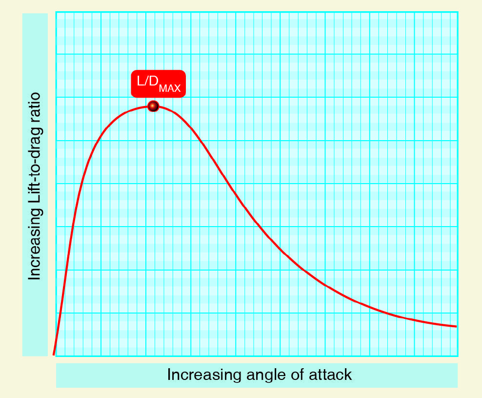
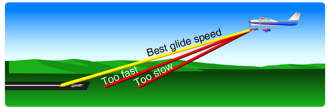
The best glide airspeed is used to maximize the distance flown. This airspeed is important when a pilot is attempting to fly during an
engine failure. The best airspeed for gliding is one at which the airplane travels the greatest forward distance for a given loss of
altitude in still air. This best glide airspeed occurs at the highest lift-to-drag ratio (L/D).
[Figure 3-23]
When gliding at airspeed
above or below the best glide airspeed, drag increases. Any change in the gliding airspeed results in a proportional change in the
distance flown.
[Figure 3-24]
As the glide airspeed is increased or decreased from the best glide airspeed, the glide ratio is lessened.
Figure 3-23.
L/D
MAX
.
Figure 3-24.
Best glide speed provides the greatest forward distance
3-22
Variations in weight do not affect the glide angle provided the pilot uses the proper airspeed. Since it is the L/D ratio that determines
the distance the airplane can glide, weight does not affect the distance flown; however, a heavier airplane needs to fly at a higher
airspeed to obtain the same glide ratio. For example, if two airplanes having the same L/D ratio but different weights start a glide
from the same altitude, the heavier airplane gliding at a higher airspeed arrives at the same touchdown point in a shorter time. Both
airplanes cover the same distance, only the lighter airplane takes a longer time.
Since the highest glide ratio occurs at maximum L/D, certain considerations should be given for drag-producing components of the
airplane, such as flaps, landing gear, and cowl flaps. When drag increases, a corresponding decrease in pitch attitude is required to
maintain airspeed. As the pitch is lowered, the glide path steepens and reduces the distance traveled. To maximize the distance
traveled during a glide, all drag-producing components need to be eliminated if possible.
Wind affects the gliding distance. With a tailwind, the airplane glides farther because of the higher groundspeed. Conversely, with a
headwind, the airplane does not glide as far because of the slower groundspeed. This is important for a pilot to understand and
manage when dealing with engine-related emergencies and any subsequent forced landing.
During powered operations, the airplane design compensates for the effects of p-factor and propeller slipstream. While these effects
disappear during a glide, the design compensation remains. During glides, it is likely that slight left rudder pressure will be required
to maintain coordinated flight. In addition, the pilot needs to use greater deflection of the flight controls due to the relatively slow
airflow over the control surfaces.
Minimum sink speed is used to maximize the time that the airplane remains in flight. It results in the airplane losing altitude at the
lowest rate. Minimum sink speed occurs at a lower airspeed than the best glide speed. Flight at the minimum sink airspeed results in
less distance traveled. Minimum sink speed is useful in flight situations where time in flight is more important than distance flown. An
example is ditching an airplane at sea. Minimum sink speed is not an often published airspeed but generally is a few knots less than
best glide speed.
In an emergency, such as an engine failure, attempting to apply elevator back pressure to stretch a glide back to the runway is likely to
lead the airplane landing short and may even lead to loss of control if the airplane stalls. This leads to a cardinal rule of airplane
flying: The pilot should
not attempt to
“stretch” a glide by
applying
back-elevator pressure and reducing the airspeed below the
airplane’s
recommended
best glide speed.
The purpose of
pitch
control during
the glide is
to
maintain
the maximum
L/D,
which
may
require fore or aft flight control pressure to maintain best glide airspeed.
To enter a glide, the pilot should close the throttle and, if equipped, advance the propeller lever forward. With back pressure on the
elevator flight control, the pilot should maintain altitude until the airspeed decreases to the recommended best glide speed. In most
airplanes, as power is reduced, propeller slipstream decreases over the horizontal stabilizer, which decreases the tail-down force, and
the airplane’s
nose tends
to
lower
immediately.
To
keep
pitch
attitude constant after
a power
change,
the pilot should
counteract the
pitch down with a simultaneous increase in elevator back pressure. This point is particularly important for fast airplanes as they do
not readily lose their airspeed—any
slight deviation
of
the airplane’s
nose downwards
results
in
an
immediate increase in
airspeed.
Once the airspeed has dissipated to best glide speed, the pitch attitude should be set to maintain that airspeed. This should be done
with reference to the natural horizon and with a quick reference to the flight instruments. When the airspeed has stabilized, the
airplane should be trimmed to eliminate any flight control pressures held by the pilot. Precision is required in maintaining the best
glide airspeed if the benefits are to be realized.
A stabilized, power-off descent at the best glide speed is often referred to as normal glide. The beginning pilot should memorize the
airplane’s
attitude and
speed
with
reference
to
the natural horizon
and
note the sounds
made by
the air
passing
over
the airplane’s
structure, forces on the flight controls, and the feel of the airplane. Initially, the learner may be unable to recognize slight variations in
airspeed and angle of bank by vision or by the pressure required on the flight controls. The instructor should point out that an increase
in sound levels denotes increasing speed, while a decrease in sound levels indicates decreasing speed. When a sound level change is
perceived, the learner should cross-check the visual and pressure references. The learner should use all three airspeed references
(sound, visual, and pressure) consciously until experience is gained, and then remain alert to any variation in attitude, feel, or sound.
After a solid comprehension of the normal glide is attained, the learner should be instructed in the differences between normal and
abnormal glides. Abnormal glides are those glides conducted at speeds other than the best glide speed. Glide airspeeds that are too
slow or too fast may result in the airplane not being able to make the intended landing spot, flat approaches, hard touchdowns,
floating, overruns, and possibly stalls and an accident.
Gliding Turns
The absence of the propeller slipstream, , p-factor, loss of effectiveness of the various flight control surfaces at lower airspeeds, and
designed-in aerodynamic corrections complicate the task of flight control coordination in comparison to powered flight for the
learner. These principles should be thoroughly explained to the learner by the flight instructor.
Three elements in gliding turns that tend to force the nose down and increase glide speed are:
3-23
1. Decrease in lift due to the direction of the lifting force.
2. Excessive rudder inputs as a result of reduced flight control pressures.
3. The normal stability and inherent characteristics of the airplane to nose-down with the power off.
These three factors make it necessary to use more back pressure on the elevator than is required for a straight glide or a level turn, and
they have an effect on control coordination. The rudder compensates for yawing tendencies when rolling in or out of a gliding turn;
however, the required rudder pedal pressures are reduced as a result of the reduced forces acting on the control surfaces. A learner
may apply excessive rudder pedal pressures based on experience with powered flight. This overcontrol of the aircraft may cause slips
and skids and result in potentially hazardous flight control conditions.
Some examples of this hazard are:
⦁
A low-level gliding steep turn during an engine failure emergency. If the rudder is excessively deflected in
the direction of the bank while the pilot is increasing elevator back pressure in an attempt to retain altitude,
the situation can rapidly turn into an unrecoverable spin.
⦁
During a power-off landing approach. The pilot depresses the rudder pedal with excessive pressure that
leads to increased lift on the outside wing, banking the airplane in the direction of the rudder deflection.
The pilot may improperly apply the opposite aileron to prevent the bank from increasing while applying
elevator back pressure. If allowed to progress, this situation may result in a fully developed cross-control
condition. A stall in this situation almost certainly results in a rapid and unrecoverable spin.
Level-off from a glide is really two different maneuvers depending on the type of glide:
⦁
First, in the event of a complete power failure, the best glide speed should be held until necessary to
reconfigure for the landing. The pilot should plan for a steeper approach than usual. A 10 percent lead (100
feet if the descent rate is 1,000 feet per minute) factor should be sufficient to slow the descent before
landing.
⦁
Second, in the case of simulated power failure training, power should be applied as the 10 percent lead
value appears on the altimeter. This allows a slow but positive power application to maintain or increase
airspeed while the pilot raises the nose to stop the descent and re-trims the airplane as necessary.
The level-off
from
a practice glide should
be started
before reaching
the desired
altitude because of
the airplane’s
downward
inertia.
The amount of lead depends on the rate of descent and the desired airspeed upon completion of the level off. For example, assume the
aircraft is in a 500 fpm rate of descent, and the desired final airspeed is higher than the glide speed. The altitude lead should begin at
approximately 100 feet above the target altitude. At the lead point, power should be increased to the appropriate level flight cruise
power
setting.
The airplane’s
nose tends
to
rise as airspeed
and
power
increase,
and
the pilot should
smoothly
control the pitch
attitude such that the level-off is completed at the desired altitude and airspeed. When recovery is being made from a gliding turn to a
normal glide, the back pressure on the elevator control, which was applied during the turn, needs to be decreased or the airplane may
pitch up and experience a loss of airspeed. This error requires considerable attention and conscious control adjustment to re-establish
a normal glide airspeed.
Common errors in the performance of descents and descending turns are:
1. Failure to adequately clear for aircraft traffic in the turn direction or descent.
2. Inadequate elevator back pressure during glide entry resulting in an overly steep glide.
3. Failure to slow the airplane to approximate glide speed prior to lowering pitch attitude.
4. Attempting to establish/maintain a normal glide solely by reference to flight instruments.
5. Inability to sense changes in airspeed through sound and feel.
6. Inability to stabilize the glide (chasing the airspeed indicator).
7. Attempting
to
“stretch” the glide by
applying
back-elevator pressure.
8. Skidding or slipping during gliding turns and not recognizing the difference in rudder forces with and without power.
9. Failure to lower pitch attitude during gliding turn entry resulting in a decrease in airspeed.
10. Excessive rudder pressure during recovery from gliding turns.
11. Inadequate pitch control during recovery from straight glide.
12. Cross-controlling during gliding turns near the ground.
13. Failure to maintain constant bank angle during gliding turns.
3-24
Chapter Summary
The four fundamental maneuvers of straight-and-level flight, turns, climbs, and descents are the foundation of basic airmanship.
Effort and continued practice are required to master the fundamentals. It is important that a pilot consider the six motions of flight:
bank, pitch, yaw and horizontal, vertical, and lateral displacement. In order for an airplane to fly from one location to another, it
pitches, banks, and yaws while it moves over and above, in relationship to the ground, to reach its destination. The airplane should be
treated as an aerodynamic vehicle that is subject to rigid aerodynamic laws. A pilot needs to understand and apply the principles of
flight in order to control an airplane with the greatest margin of mastery and safety.
3-25
Airplane Flying Handbook (FAA-H-8083-3C)
Chapter 4: Energy Management: Mastering Altitude and Airspeed Control
Introduction
This
chapter
is
all about managing
the airplane’s
altitude and
airspeed
using
an
energy-centered approach. Energy management can
be defined
as the process
of
planning,
monitoring,
and
controlling
altitude and
airspeed
targets in
relation
to
the airplane’s energy
state in order to:
1.
Attain and maintain desired vertical flightpath-airspeed profiles.
2.
Detect, correct
,
and prevent unintentional altitude-airspeed deviations from the desired energy state.
3.
Prevent irreversible deceleration and/or sink rate that results in a crash.
Importance of Energy Management
Learning to manage the airplane’s energy in the form
of
altitude and airspeed is critical for all new pilots. Energy management
is essential for effectively achieving and maintaining desired vertical flight path and airspeed profiles
,
(e.g.
,
constant airspeed climb)
and for transitioning from one profile to another during flight
,
(e.g.
,
leveling off from a descent).
Proper energy management is also critical to flight safety. Mistakes in managing the airplane’s energy state can be deadly.
M
ismanagement of mechanical energy (altitude and/or airspeed) is a contributing factor to the three most common types of fatal
accidents in aviation: loss of control in
-
flight (LOC-I), controlled flight into terrain (CFIT), and approach-and-landing accidents.
Thus, pilots need to have:
1. An accurate mental model of the airplane as an energy system.
2. The competency to effectively coordinate control inputs to achieve and maintain altitude and airspeed targets.
3. The ability to identify, assess, and mitigate the risks associated with mismanagement of energy.
Viewing the Airplane as an Energy System
The total mechanical energy of an airplane in flight is the sum of its potential energy from altitude and kinetic energy from airspeed.
The potential energy is expressed as
mgh
, and the kinetic energy as
½ mV²
. Thus, the airplane's total mechanical energy can be stated
as:
mgh + ½ mV²
Where,
m = mass
g = gravitational constant
h = height (altitude)
V = velocity (airspeed)
A
flying
airplane is
an
“open” energy
system,
which
means
that the airplane can
gain
energy
from
some source
(e.g.,
the fuel tanks)
and lose energy to the environment (e.g., the surrounding air). It also means that energy can be added to or removed from the
airplane’s
total mechanical energy
stored
as altitude and
airspeed.
A Frame of Reference for Managing Energy State
At any given time, the energy state of the airplane is determined by the total amount and distribution of energy stored as altitude and
airspeed.
Note that the pilot’s
frame of
reference
for
managing
the airplane’s
energy
state is
airplane-centric—being a function of
indicated altitude and indicated airspeed, and not height above the ground or groundspeed.
The indicated altitude displayed in the altimeter and its associated potential energy are based on the height of the airplane above a
fixed reference point (mean sea level or MSL), not on the height above ground level (AGL), which changes with variations in terrain
elevation. Likewise, the indicated airspeed displayed in the airspeed indicator and its associated kinetic energy are based on the speed
of the airplane relative to the air, not on the speed relative to the ground below, which varies with changes in wind speed and
direction.
4-1
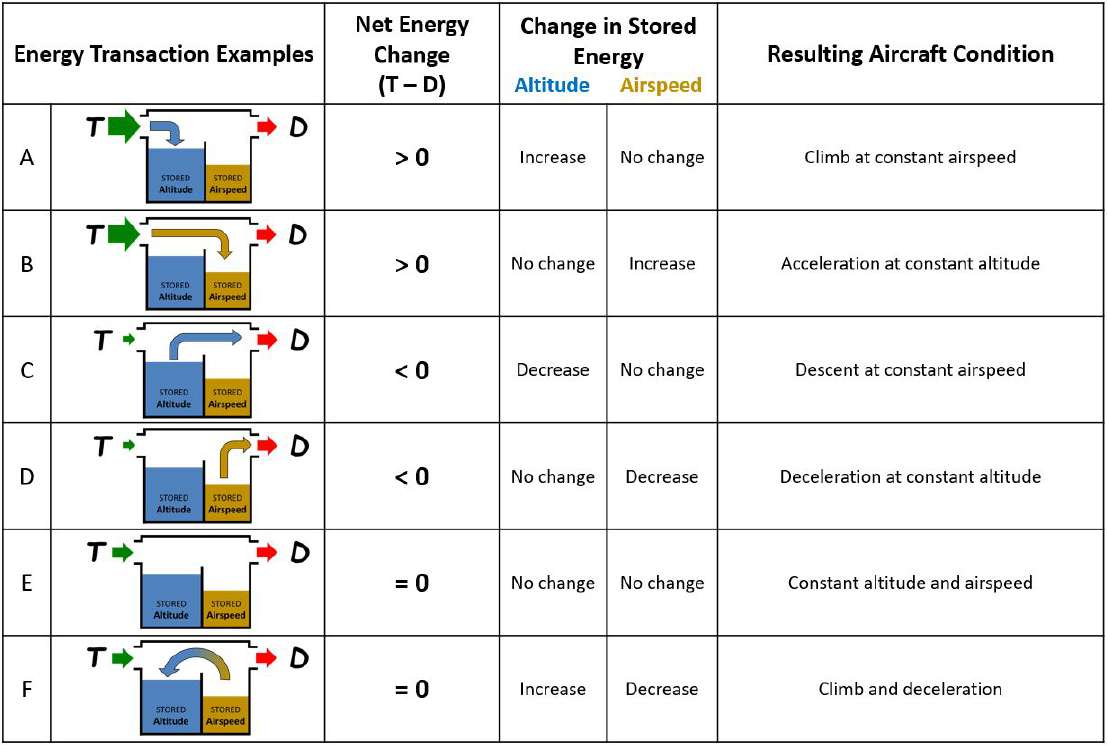
Note that changes in indicated altitude and airspeed are attained through forces resulting from the pilot’s direct manipulation of the
controls. These direct control inputs determine the airplane’s ability to climb/descend or accelerate/decelerate. In contrast,
changes in
AGL-altitude and groundspeed are
affected by
“external” factors, such as
varying
terrain elevation and wind, which
the pilot cannot alter. Of course, the pilot should manipulate the airplane’s energy in such way as to minimize any risks
associated with terrain or wind. For example, the pilot may seek to manipulate energy state so as to maximize the airplane’s energy
gains and minimize energy loses when faced with rising terrain. A safer heading may also be an option.
Once airborne, the airplane gains energy from the force of engine thrust (
T
) and it loses energy from aerodynamic drag (
D
). The
difference between energy in and out (
T –
D
) is the net change, which determines whether total mechanical energy—stored as altitude
and airspeed—increases, decreases, or remains the same.
When thrust exceeds drag (
T –
D > 0
), the airplane's total mechanical energy increases. The pilot can store the surplus energy as
increased altitude or airspeed. For example, if the pilot decides to put all the surplus energy into altitude, the airplane can climb at a
constant airspeed.
[Figure 4-1A]
If the pilot opts to place all the surplus energy into airspeed, the airplane can accelerate while
maintaining altitude.
[Figure 4-1B]
When drag exceeds thrust, (
T –
D < 0
), the airplane's total mechanical energy decreases. The pilot has two sources of stored energy to
tap into. For example, the pilot may choose to let the airplane descend at a constant airspeed
[Figure 4-1C)]
or slow down while
maintaining altitude
[Figure 4-1D]
as stored energy is withdrawn to deal with the energy deficit. When energy gained equals that lost
(
T –
D = 0
), all thrust is spent on drag. In this case, the total amount of mechanical energy and its distribution over altitude and
airspeed does not change. Both remain constant as the airplane maintains a constant altitude and airspeed.
[Figure 4-1E]
Energy can also be exchanged between altitude and airspeed. For example, when a pilot trades airspeed for altitude, as altitude
increases, airspeed decreases. In other words, when energy is exchanged, altitude and airspeed always change in opposite directions
(absent any other energy or control inputs). As one goes up, the other one comes down. Also note that even though the distribution of
energy over altitude and airspeed may change dramatically during energy exchange, the total amount of mechanical energy can
remain the same at the end of the exchange maneuver
[Figure 4-1F],
as long as thrust is adjusted to match drag as the latter varies
with changes in airspeed.
Figure 4-1 A-F.
Examples of typical energy transactions.
4-2
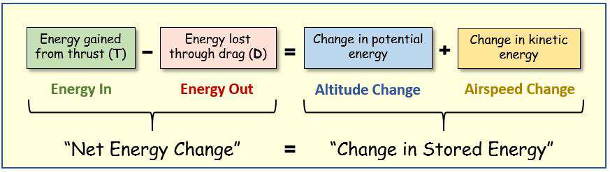
Managing Energy is a Balancing Act
Since the airplane gains energy from engine thrust (
T
) and loses energy through aerodynamic drag (
D
), energy flows
continuously into and out of the airplane while in flight. Usually measured as
Specific Excess Power
(
P
S
), or rate of energy change,
the net energy flow is a direct function of the difference between thrust and drag.
P
S
= (T –
D)V/W
Where,
T = Thrust
D = Drag
V = velocity (airspeed)
W = aircraft weight
More importantly,
there is
a fundamental relationship
between
changes in
the airplane’s
total energy
resulting
from
this
net energy
flow on one hand, and changes in the energy stored as altitude and airspeed on the other. This fundamental relationship can be
summarized
through
the airplane’s
energy
balance
equation.
[Figure 4-2]
Figure 4-2.
The energy balance equation.
The left side of
the energy
balance
equation
represents
the airplane’s
net energy
flow,
while the right side reflects matching changes
to
the
energy
storage.
Thus,
changes
to
the
airplane’s
total
energy
affect
the
left
side
of
the
equation,
while
the
right
side shows
possible changes in energy distribution between altitude and airspeed.
Note that a change in total energy resulting from the difference between thrust and drag (left side) always matches the change in total
energy redistributed over altitude and airspeed (right side). Although rate of energy change
, expressed as specific excess power (
P
S
)
,
varies during flight—becoming positive, negative
,
or zero—both sides of the equation are inexorably balanced regardless of whether
the airplane is accelerating, decelerating, climbing, descending, or maintaining constant altitude and airspeed.
(Note: This
simplified balance equation does not account for long-term changes in total mechanical energy caused by the reduction in
aircraft weight as fuel is gradually burned in flight. Although the effect of weight loss on total energy becomes critical when
solving long-term aircraft performance problems such as range and endurance, it is negligible when considering short-term flight
control problems.)
Of course, the pilot controls the change in total energy on the left side of the equation, as well as the distribution of any changes in
energy over altitude and airspeed on the right side. How the pilot coordinates the throttle and elevator to achieve and maintain desired
altitude and airspeed targets as well as avoid energy "crises" is at the core of energy management and is elaborated in the rest of the
chapter.
Role of the Controls to Manage Energy State
An energy-centered approach clarifies the roles of the engine and flight controls beyond the simple “pitch for airspeed and power for
altitude” by modeling how throttle and elevator inputs affect the airplane’s total mechanical energy.
From an energy perspective, the
problem of controlling vertical flight path and airspeed becomes one of handling the airplane’s energy state—the total amount
of energy and its distribution over altitude and speed. Thus, rather than asking what controls altitude and what controls airspeed, a
pilot can now ask what controls total energy and what controls its distribution over altitude and airspeed.
4-3
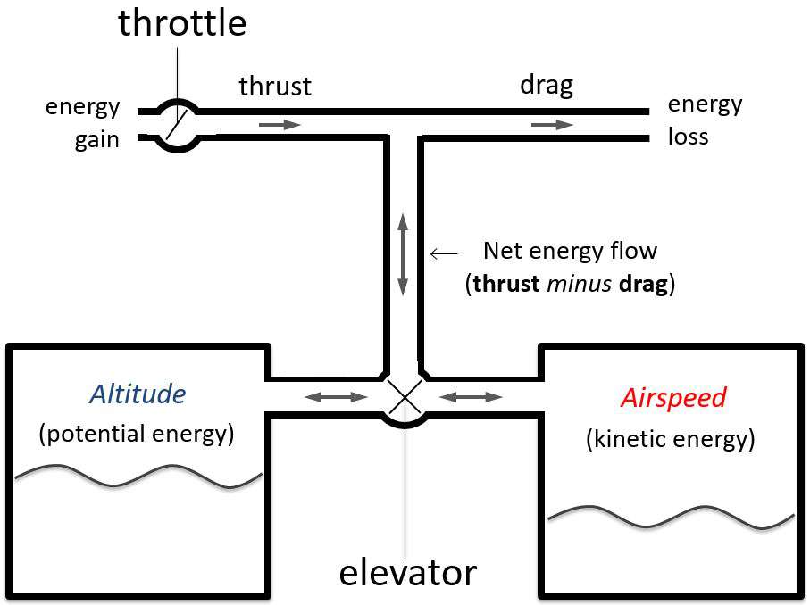
Primary Energy Role of the Throttle and Elevator
The throttle, by increasing or decreasing engine thrust against drag, regulates changes in total mechanical energy. As illustrated
above, changing total energy is a function of both thrust and drag (
T –
D
). However, drag mainly varies long-term due to airspeed
changes, or by using high lift/drag devices which can only increase drag. Therefore, changes in total energy are normally initiated by
changing thrust, not drag. When the throttle setting makes thrust greater than drag, an increase of total mechanical energy is the result.
When the throttle setting makes thrust less than drag, a decrease of total mechanical energy is the result. Once the desired path-speed
profile is established, the throttle sets engine thrust to match the total energy demanded by vertical flight path and airspeed combined.
The throttle then is the
total energy controller
.
On the other hand, the elevator is an energy exchanger and distribution device whose primary job is to allocate changes in total
energy between vertical flight path and airspeed by adjusting pitch attitude. Here, once the chosen path-speed profile is achieved, the
elevator sets the appropriate pitch attitude to maintain the demanded distribution of total energy over vertical flight path and airspeed.
Thus, the elevator is the
energy distribution controller
.
The throttle and elevator then are really energy state controls—neither one controls altitude nor airspeed independently since these
two
variables
are
inherently
coupled
through
the
airplane’s
total
mechanical
energy.
Instead,
to
control
altitude
and
airspeed
effectively, the pilot coordinates the use of both devices to manage the airplane’s energy state.
The reservoir analogy
[Figure 4-3]
illustrates the energy-based role of the throttle and the elevator. In this analogy, the throttle
controls
the “valve”
regulating
the net total energy
flow
while the elevator
controls
the “valve”
regulating
the distribution
of energy
into
and
out
of
the
altitude
and
airspeed
“reservoirs.”
Referring
back
to
the
energy
balance
equation
[
Figure 4-2
], it becomes clear
then that the throttle controls the left side of the equation (total energy) and the elevator controls the right side (energy distribution).
As illustrated in
Figure 4-3
, when the throttle increases thrust above drag (
T –
D > 0
) the airplane gains total energy, and when the
throttle reduces thrust below drag (
T –
D < 0
) the airplane loses total energy. The elevator then distributes this increase or decrease in
total energy between altitude and airspeed. Finally, when the throttle adjusts thrust equal to drag (
T –
D = 0
), there is no change in
total energy, but the energy stored as altitude and airspeed can be exchanged between the two reservoirs using the elevator, while total
energy, at least short-term, remains constant.
Figure 4-3.
The reservoir
analogy illustrating
the primary role of the throttle and
elevator
to
manage the airplane’s
energy state.
4-4
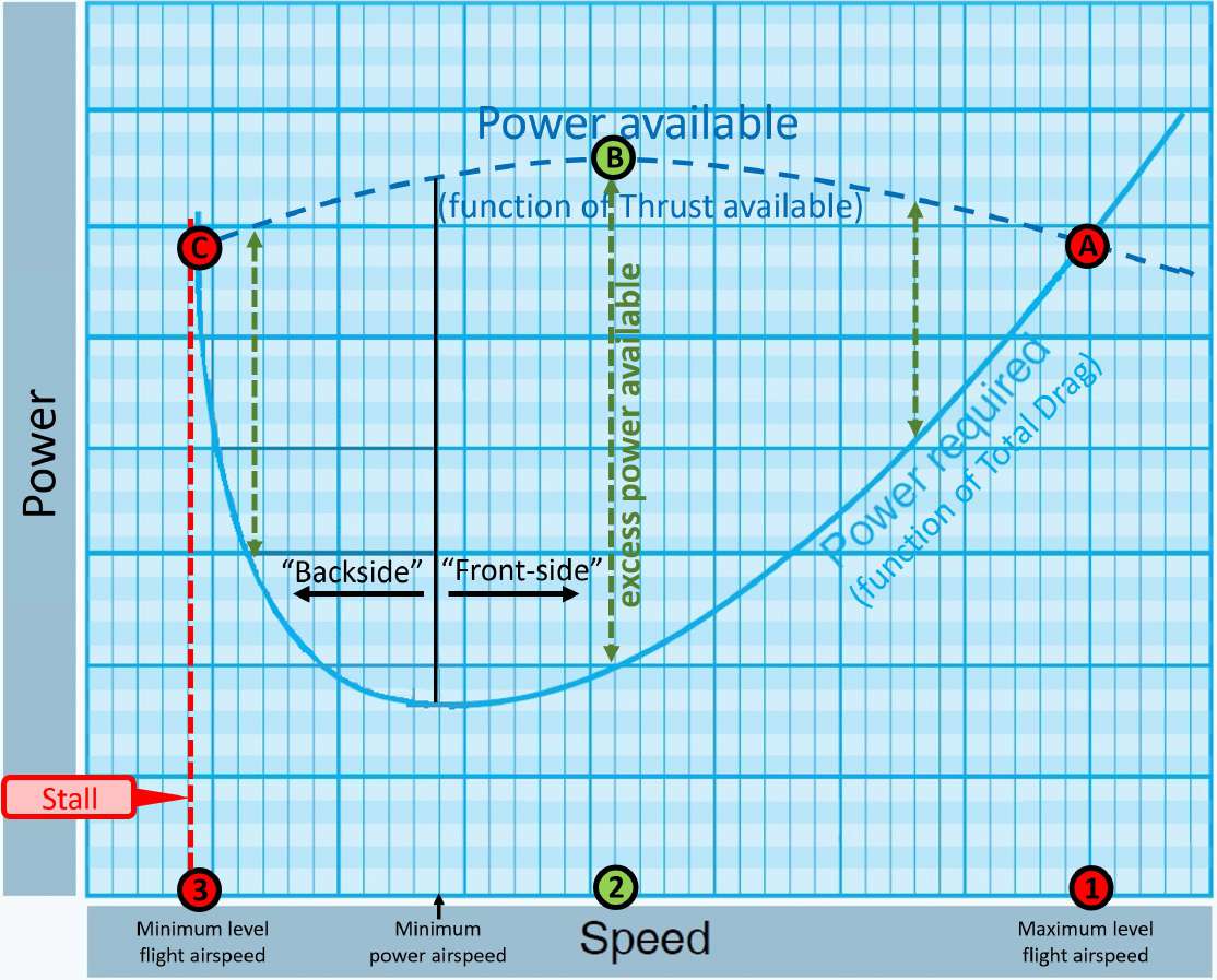
Additional Role for the Elevator
On the front side of the power required curve, where the airplane cruises at high speed (1 in
Figure 4-4
) and a low angle of attack
(AOA) with little or no excess power or excess thrust (A in
Figure 4-4
), pulling back on the yoke or stick (elevator up) will result in a
brief energy exchange climb, causing the airplane to slow down from 1 to 2 toward the center of the power curve
[Figure 4-4]
. This
decrease in airspeed results in a reduction in total drag; hence available energy in the form of positive excess power (
P
S
> 0
) where
thrust exceeds drag (
T –
D > 0
). With this excess power (B in
Figure 4-4
) the airplane can now climb at a constant airspeed or turn in
level flight while maintaining a constant airspeed at an increased load factor.
On the backside of the power required curve, where the airplane flies at low speed (3 in
Figure 4-4
) and high AOA with little or no
excess power or excess thrust (C in
Figure 4-4
), pushing forward on the yoke or stick (elevator down) will result in a brief energy
exchange descent, causing the airplane to accelerate from 3 to 2 toward the center of the power curve
[Figure 4-4]
. This increase in
airspeed results in a reduction in total drag; hence available energy in the form of positive excess power (
P
S
>0
) where thrust exceeds
drag (T –
D > 0). With this excess power (B in
Figure 4-4
) the airplane can now climb at a constant airspeed or turn in level flight
while maintaining a constant airspeed at an increased load factor. This role of the elevator is critical to prevent unintentional,
excessive deceleration or sink rate as illustrated later in the chapter (refer to
Preventing Irreversible Deceleration and/or Sink Rate
section).
Figure 4-4.
The front side and backside of the power
required
c
urve
, the power available curve, and the r
elative excess power
available (power available - power required) at different speeds
.
4-5
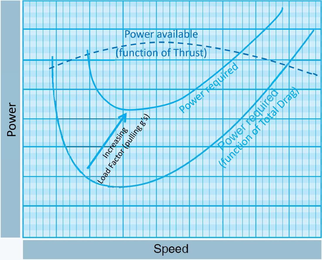
While the elevator can assist the throttle in changing
T –
D
and
P
S
through changes in airspeed via energy exchange as described
above,
occasionally
the
elevator
can
directly
increase
the
“D”
in
T –
D
at any given speed during a level turn, thus helping the
airplane rapidly bleed off total energy.
As the airplane banks, load factor (lift/weight) increases because total lift has to increase to
pull the airplane into the turn while simultaneously balancing its weight. This is accomplished by pulling back on the yoke (or stick)
to increase AOA which results in increased induced drag and power required at any given speed
. This action will quickly slow
the airplane
down and
decreas
e
total energy more rapidly than by just reducing the throttle setting to idle. This additional role of the
elevator is shown on the power curve.
[Figure 4-5]
Figure 4-5.
T
he
effect of increased load factor on total
drag and
power required at different airspeeds
.
Applying the respective role of the controls to manage the airplane’s energy state leads to a set of simple “rules” for proper throttle-
elevator coordination to effectively control vertical flight path and airspeed. What are these basic rules of energy control?
Rules of Energy Control
The central principle encapsulating the role of the throttle and elevator for managing the airplane’s energy can be summed up
as follows: coordinated throttle and elevator inputs control the airplane’s energy state.
Modifying a popular adage, the principle can
be restated as “pitch plus power controls energy state.”
This central principle serves to guide a set of general energy control rules to
achieve and maintain any desired vertical flight path and airspeed targets within the airplane’s energy envelope.
4-6
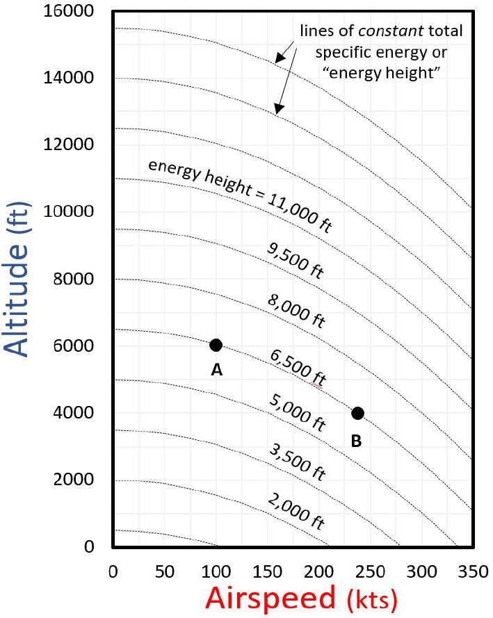
Visualizing the Airplane’s Ability to “Move” Between Energy States
To
better
understand
the
basic
rules
of
energy
control,
a pilot
needs
to
visualize
an
airplane’s
energy
state
and
its
ability
to switch
from one energy state to another. In other words, how does an airplane “move” from an initial altitude and airspeed to any other target
altitude and airspeed within its flight envelope, and how does the pilot control the process? A map
should
help
, and in this case, it
charts the status of the aircraft in terms of energy
.
In a navigation map, such as an aeronautical sectional chart, the geographic position of an airplane is determined by two variables—
latitude and longitude. Likewise, in an “altitude-airspeed” or “energy” map the energy position of an airplane, its energy state,
is defined by two variables—altitude and airspeed.
[Figure 4-6]
Figure 4-6.
The altitude-speed “map” showing lines of constant energy height.
The position of an airplane in the altitude-airspeed map represents its total specific energy or
E
S
(which is simply the sum of its
potential and kinetic energies divided by aircraft weight) as determined by its current altitude and airspeed.
E
S
= h + V²
2g
Where,
g = gravitational constant
h = height (altitude)
V = velocity (airspeed)
4-7
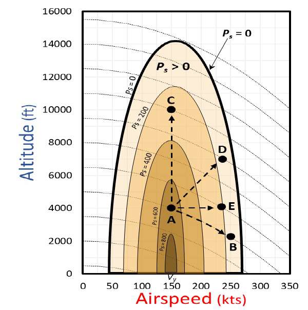
Since the total specific energy,
E
S
, has the units of height (e.g.
,
feet), it is usually called energy height. It also gets this name from the
fact that energy height is the
maximum
height that an airplane would reach from its current altitude, if it were to trade all its speed for
altitude.
Figure 4-6
shows lines of constant total specific energy or energy height. Different positions of an airplane along a given
energy height line have the same total energy regardless of their location on the line (e.g., A and B).
Thus, even though the airplane in point A is cruising at 100 knots and 6,000 feet, it has the same total specific energy expressed in
height (6,500 feet) when cruising at 240 knots and 4,000 feet (B). This also means that the airplane in either position, A or B, would
be able to
“zoom” to
the same maximum
altitude of
6,500
feet by
trading
all its
speed
for
altitude.
The lines of
constant energy height
can be used as idealized trajectories to depict an airplane moving from one energy state to another solely through energy
exchange (e.g.
,
A to B). If the airplane rapidly exchanges altitude and airspeed, it would follow along the energy height line while, in
the short term, maintaining constant total energy.
In addition to showing energy height lines, the energy map can also depict available specific excess power (
P
S
) contours, as well as
energy trajectories of an airplane moving from one energy state to another.
[Figure 4-7]
The airplane can move along energy height
lines by simply exchanging energy (e.g., A to B). However, to move across energy height lines, the airplane needs to increase or
decrease total energy while distributing the energy change between altitude and airspeed. Thus, the ability of an airplane to go from
one energy height to another (e.g.
,
from A to positions C, D, or E) is a function of specific excess power (
P
S
), measured in rate
of change in distance or height (e.g.
,
feet per minute).
Examine the energy positions depicted in
Figure 4-7
. The airplane in position A is flying at 4,000 feet and 150 knots with a total
energy equivalent to 5,000 feet. Since positions C, D and E are located at higher energy heights (11,000, 9,500, and 6,500 feet
respectively), the only way for the airplane to reach them from position A is by increasing its total energy (i.e., increasing
thrust above drag, or
P
S
> 0
). The reverse is also true. If the airplane is in position C, D or E, the only way for it to get back to
position A is by decreasing its total energy (i.e., decreasing thrust below drag, or
P
S
< 0
). In other words, the rate at which the
airplane can move from one energy height to another—e.g., how swiftly it can climb/descend at a steady speed, or accelerate/
decelerate in level flight—is a function of specific excess power, which can be positive (
P
S
> 0) or negative (
P
S
< 0) depending on
whether the airplane needs to move to an energy height that demands more or less total energy.
At the edge of the energy envelope, where available
P
S
= 0 at full throttle, the airplane can no longer climb while maintaining
airspeed or accelerate without descending. Inside this envelope, inner contours increase in value, reaching a “peak” where available
P
S
is maximized. Notice that
P
S
at full throttle is maximized at a specific airspeed (
V
Y
) decreasing in value at slower or faster
airspeeds. At
V
Y
then, the airplane can attain the maximum rate of climb while maintaining airspeed or the maximum acceleration
without descending
[Figure 4-7]
.
Figure 4-7.
Energy map depicting specific excess power (P
S
) contours (shown in feet per minute) and energy trajectories for a
hypothetical airplane.
4-8
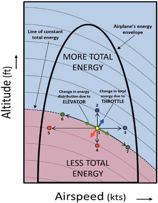
Three Basic Rules of Energy Control
An
“energy-control” map
can
help
visualize
the basic energy
control rules.
[Figure 4-8]
The energy-control map depicts not only the
trajectories of an airplane transitioning from an arbitrary initial energy state (1) to other target states (2, 3, 4, 5, 6, and 7), but also the
changes in energy caused by the throttle (blue/red arrows) and the elevator (green arrows). In other words, it allows pilots to visualize
the basic control rules for moving an airplane from any state to another. The edge of the sustainable energy state envelope (where
P
S
= 0
at full throttle) is also illustrated.
Note that the line of constant total energy (dashed line) that divides the area in the map requiring more total energy (blue area) from
that which requires less energy (red area) is depicted relative to the arbitrary initial energy state (1). The throttle adds (blue arrow) or
subtracts (red arrow) the amount of total energy demanded by the new target energy state, while the elevator (green arrows)
distributes the correct amount of total energy between potential and kinetic energies. By balancing the simultaneous actions of the
controls, the airplane can follow the desired energy trajectory.
As illustrated in
Figure 4-8
, moving the airplane from position 1 to the energy states in 2 and 3 calls for a higher throttle setting to
increase total energy by the same amount (in this example, positions 2 and 3 are located at the same higher
-
energy height).
The difference between these two energy trajectories (1-to-2 and 1-to-3) lies in the way the total energy change is distributed
by the elevator through changes in pitch attitude. As can be seen in
Figure 4-8
, changes in total energy by adjusting throttle setting
(blue/red arrows) extend across lines of constant total energy (dashed line), while changes in energy distribution by adjusting
the elevator deflection (green arrows) extend along the lines of constant total energy (equal energy height). Appropriate changes in
total energy via the throttle and/or changes in energy distribution via the elevator, depicted by their
respective
energy “arrows,”
determine the direction of a given energy trajectory between two energy states. To visualize this effect, compare
the
trajector
y
from 1-to-2
with that
from 1-to-3 and
notice
the way the corresponding elevator energy arrows (left green arrow =
up-elevator; right green arrow = down-elevator) are positioned in relation to the throttle energy arrow (blue arrow = increased
throttle).
Figure 4-8.
The energy-control map helping to visualize the basic energy control rules.
4-9
Thus, transitioning to a higher altitude at a constant speed (1-to-2) requires increased throttle and up
-
elevator to stay on speed, while
transitioning to a faster airspeed at a constant altitude (1-to-3) demands increased throttle and (gradual) down
-
elevator to stay on path,
re-trimming as needed to relieve elevator control pressures.
Transitioning to a lower altitude at a constant speed (1-to-4) requires decreased throttle and down
-
elevator to stay on speed, while
transitioning to a slower airspeed at a constant altitude (1-to-5) demands decreased throttle and (gradual) up
-
elevator to stay on path,
re-trimming as needed to relieve elevator control pressures.
Finally, transitioning to a higher altitude by trading speed for altitude (1-to-6) requires up
-
elevator without initially changing throttle
setting, while transitioning to a faster airspeed by trading altitude for speed (1-to-7) requires down
-
elevator without initially changing
throttle setting. In both cases, at the end of the energy exchange maneuver,
the
elevator will need to be re-trimmed and throttle
setting adjusted to match drag at the new speed in order to maintain total energy constant while remaining at the new altitude-airspeed
target.
As can be visualized in
Figure 4-8
, there are three general energy control rules for coordinating the throttle and elevator to move the
airplane from
one
energy state to another:
R
ule
#1:
If
you want to move to a new energy state that demands more total energy,
then
:
Throttle:
increase throttle setting so that thrust is greater than drag, thus increasing total energy;
Elevator:
adjust pitch attitude as appropriate to distribute the total energy being gained over altitude and airspeed:
a. To climb at constant speed, pitch up just enough to maintain the desired speed;
b. To accelerate at constant altitude, gradually pitch down just enough to maintain path.
Upon reaching new desired energy state, adjust pitch attitude and throttle setting as needed to maintain the new path-speed
profile.
R
ule
#2:
If
you want to move to a new energy state that demands less total energy,
then
:
Throttle:
reduce throttle setting so that thrust is less than drag, thus decreasing total energy;
Elevator:
adjust pitch attitude as appropriate to distribute the total energy being lost over altitude and airspeed:
a. To descend at constant speed, pitch down just enough to maintain the desired speed;
b. To slow down at constant altitude, gradually pitch up just enough to maintain path.
Upon reaching new desired energy state, adjust pitch attitude and throttle setting as needed to maintain the new path-speed
profile.
R
ule
#3:
If
you want to move to a new energy state that demands no change in total energy,
then
:
Throttle:
do not change initially, but adjust to match drag at the end of maneuver as needed to maintain total energy constant;
Elevator:
adjust pitch attitude to exchange energy between altitude and airspeed:
a. To trade speed for altitude, pitch up;
b. To trade altitude for speed, pitch down.
Upon reaching new desired energy state, adjust pitch attitude and throttle setting as needed to maintain the new path-speed
profile.
Note that control rules 1 and 2 allow the elevator to distribute the change in total energy in different ways. For example, using rule
1.a the pilot may choose to adjust the pitch-up attitude to climb at a slower (or faster) airspeed. Other situations may require
combining two control rules. One example is when, at maximum cruise airspeed in level flight, thrust has reached its maximum limit
(i.e.
,
P
S
= 0) but the target energy state is at a higher altitude and total energy within the airplane’s envelope. At maximum
level airspeed, there is no excess thrust available to increase the airplane’s total energy needed to climb. One solution is to initially
trade kinetic for potential energy (rule 3.a), slowing down to an airspeed where drag is reduced below thrust, thus allowing the
airplane to increase its total energy and climb at that slower airspeed (rule 1.a).
4-10
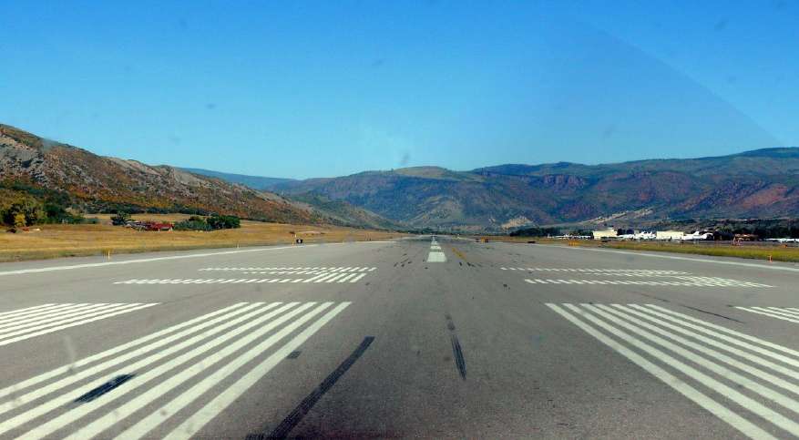
Mitigating Risks from Mismanagement of Energy
Besides learning the proper use of the controls for normal energy management tasks, pilots should be equipped with the ability to
identify, assess, and mitigate two major risks associated with mismanagement of energy: 1)
unwanted deviations from the
desired energy state; and 2) unintentional, irreversible deceleration and/or sink rate
causing depletion of mechanical energy
. The
first risk involves unintended altitude-airspeed deviations (refer to
Managing Energy Errors
section). The second risk entails
unforeseen, continuous airspeed and/or altitude loss coupled with little or no available excess power in a given flight condition (refer
to
Preventing Irreversible Deceleration and/or Sink Rate
section).
Two Energy Management Scenarios
Two flight scenarios illustrate the two major risks associated with failure to manage the airplane's energy state and how a pilot can
identify, assess, and mitigate those risks.
Scenario 1
Unintentionally descending below the desired glideslope on final approach to landing and failing to make the proper correction.
[Figure 4-9]
To bring the airplane back to the desired glideslope, should the pilot pitch up, throttle up, or both?
Figure 4-9.
Descending below the desired glideslope.
Scenario 2
Flying toward rising terrain and not being able to fly up and over it before impacting terrain.
[Figure 4-10]
Note the rising terrain all
along the departure corridor. What can the pilot do to prevent an impending crash?
Figure 4-10.
Departing from Runway 33, Aspen/Pitkin County Airport (KASE), elevation 7,820 feet.
For both scenarios, this section will demonstrate how proper energy management can provide the pilot with the skill to manage the
associated risks and avoid tragic results.
4-11
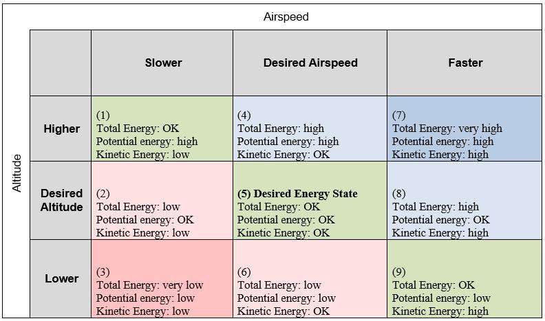
Managing Energy Errors
In addition to learning effective techniques for maintaining stabilized path-speed profiles (
e.g.,
tracking the glideslope)
and transitioning from one profile to another during flight (
e.g.,
leveling off from a descent), pilots should develop skills for
managing unwanted deviations in vertical flight path and airspeed—returning the airplane to its target energy state. Since many
inflight “energy crises” start as undetected, ignored or poorly managed path-speed deviations, pilots need the skills to recognize,
correct and prevent these deviations.
Although
the intention
is
to
correct altitude and
airspeed
deviations,
the pilot is
always
acting
on
the airplane’s
energy
state. Thus, it
is important to translate altitude-speed deviations into energy errors.
[Figure 4-11]
Because the airplane’s
total energy
is
distributed
over altitude and airspeed, there are two types of energy errors: 1) total energy errors and 2) energy distribution errors.
Figure 4-11
.
An energy state matrix that translates the main altitude-speed deviations into energy errors relative to the desired energy
state (5).
Monitoring the altimeter (or other flight path reference) and airspeed indicator allows the pilot to distinguish these two types of
energy errors. In total energy errors, the airplane has too much energy (blue boxes) or too little energy (red boxes). The pilot will
notice that altitude and
speed
deviate in
the same direction
(“lower-and-slower” or
“higher-and-faster”).
On
the other
hand,
in
energy
distribution errors the airplane may have the correct amount of total energy (green boxes) but its distribution over altitude and speed is
incorrect. Here, altitude and speed deviate in opposite directions (“higher-and-slower” or “lower-and-faster”). I
n this case, the
pilot deals
with relative deviations—not absolute altitude and speed.
Following energy management principles, total energy errors are corrected by increasing or decreasing energy using the throttle,
while energy distribution errors are corrected by exchanging energy between altitude and speed using the elevator. To correct a
combination of total energy and distribution errors, both controls need to be used simultaneously.
Figure 4-12
summarizes the control
skills needed to correct total energy and energy distribution errors.
Scenario 1
[Figure 4-9]
is a good example to illustrate energy errors and the skills needed to correct and avoid them.
Figure 4-13
actually depicts three possible scenarios (B, C, and D) where an airplane on final approach to land has descended below its intended
flight path. Should the pilot pitch up, throttle up, or both? It depends. The airplane is lower than desired, but the pilot should check
the airspeed as well. Relative to the target airspeed, the actual speed may be slower (B), faster (D), or on target (C). In all three cases,
the goal is to return the airplane to its correct energy state (A), following a deviation in altitude and/or airspeed.
Lower-and-slower (B) is fundamentally different from lower-and-faster (D). The former requires advancing the throttle forward to
regain total energy (3 in
Figure 4-12
), while the latter requires pulling back on the yoke/stick to null the energy distribution error (9
in
Figure 4-12
).
4-12
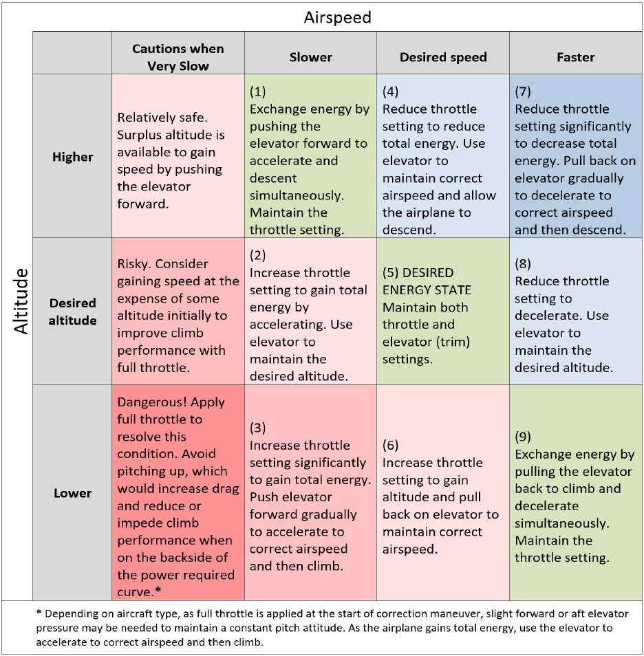
Figure 4-12.
The control skills needed to correct total energy and energy distribution errors identified in Figure 4-11 with an
additional
column
giving
caution
to
the
“very slow”
condition
where
careful
AOA
management
is
needed
in
addition
to
energy
management.
Note that in the scenario depicted in B in
Figure 4-13
, ad
vancing the throttle forward
to increase energy would only succeed if
excess thrust is available (
P
S
> 0
). This may not be the case if the pilot has badly mismanaged energy and slowed down to a
speed where induced drag is so high that even applying full throttle would result in no surplus energy (see column "Cautions When
Very Slow" in
Figure 4-12
). Depending on the flight condition, available excess power at full throttle may be negative (
P
S
< 0
).
In this case, the only recourse is to first trade altitude for speed by pushing forward on the yoke/stick, reducing AOA and
induced drag, and only then advancing the throttle forward to regain total energy. But if the airplane is too close to the ground, there
may not be enough room to reverse the negative energy rate and prevent the airplane from striking the ground.
Now consider the scenario depicted in C in
Figure 4-13
, where the airplane has descended below the desired flight path but is flying
at the correct speed. Here, even though there is no speed deviation, the pilot is faced with a combination of total energy and
distribution errors. Regaining altitude without changing speed requires ad
vancing the throttle forward
while easing aft on the yoke
/
stick
(6 in
Figure 4-12
). In other words, decoupling altitude and airspeed (i.e. changing one without changing the other) demands
the use of both controls simultaneously.
In all cases, path and speed should be monitored carefully as they are corrected, adjusting pitch attitude and throttle setting as
appropriate. Once short-term deviations are corrected, the airplane will need to be trimmed for long-term control to maintain the
desired path-speed profile (5 in
Figure 4-12
).
4-13
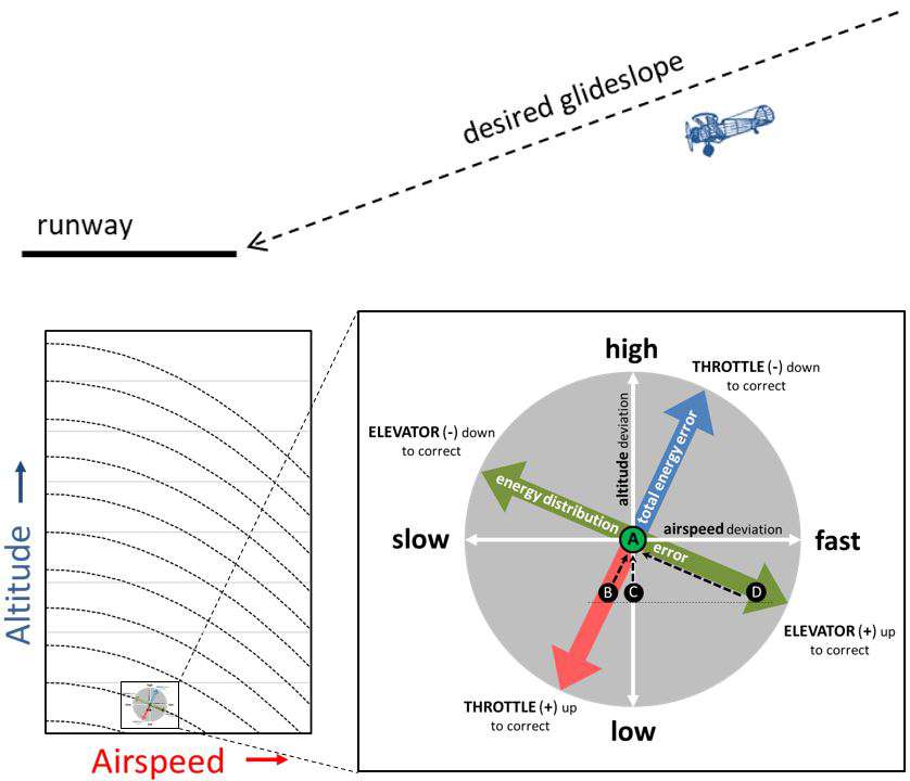
Figure 4-13.
Energy error management.
The above approach-to-landing scenario is just one example illustrating the risk of mismanaging altitude-speed deviations.
Pilots need to be able to identify, assess
,
and mitigate altitude and/or airspeed deviations during any phase of flight, including traffic
pattern operations, take-offs and climbs, cruise flight, descending flight, and any procedure or maneuver involving turns.
Clearly, skills for promptly correcting path-speed deviations can enhance flight safety but the pilot should also be aware of the risk of
unrecoverable
depletion
of
the
airplane’s
mechanical
energy,
especially
as the
airplane
approaches
the
edges
of
its
flight
envelope
where available excess power is zero.
Preventing Irreversible Deceleration and/or Sink Rate
During normal flight, the airplane experiences many instances of negative energy rates (negative specific excess power or
P
S
< 0
)
while decelerating at a constant altitude or descending at a constant airspeed; these are intended energy bleed rates. However, one of
the greatest
dangers
from
mismanaging
the airplane’s
energy
state is
encountering
unintended,
excessive deceleration
and/or
sink rate
coupled with little or no positive excess power available under a given flight condition. Failure to recover above a certain critical
altitude results in depletion of mechanical energy. Regardless of what the pilot does past that point, the airplane will hit the ground.
To
help
pilots
understand
the
risk
of
unintended
energy
depletion,
let’s
take
a closer
look
at Scenario
2
[Figure 4-10]
. This flight
scenario illustrates a situation that is all too common in general aviation: flying toward rising terrain and not being able to fly up and
over it before impacting terrain.
As
shown in
Figure 4-10
, there is rising terrain all along the departure corridor. The scenario is as follows:
4-14
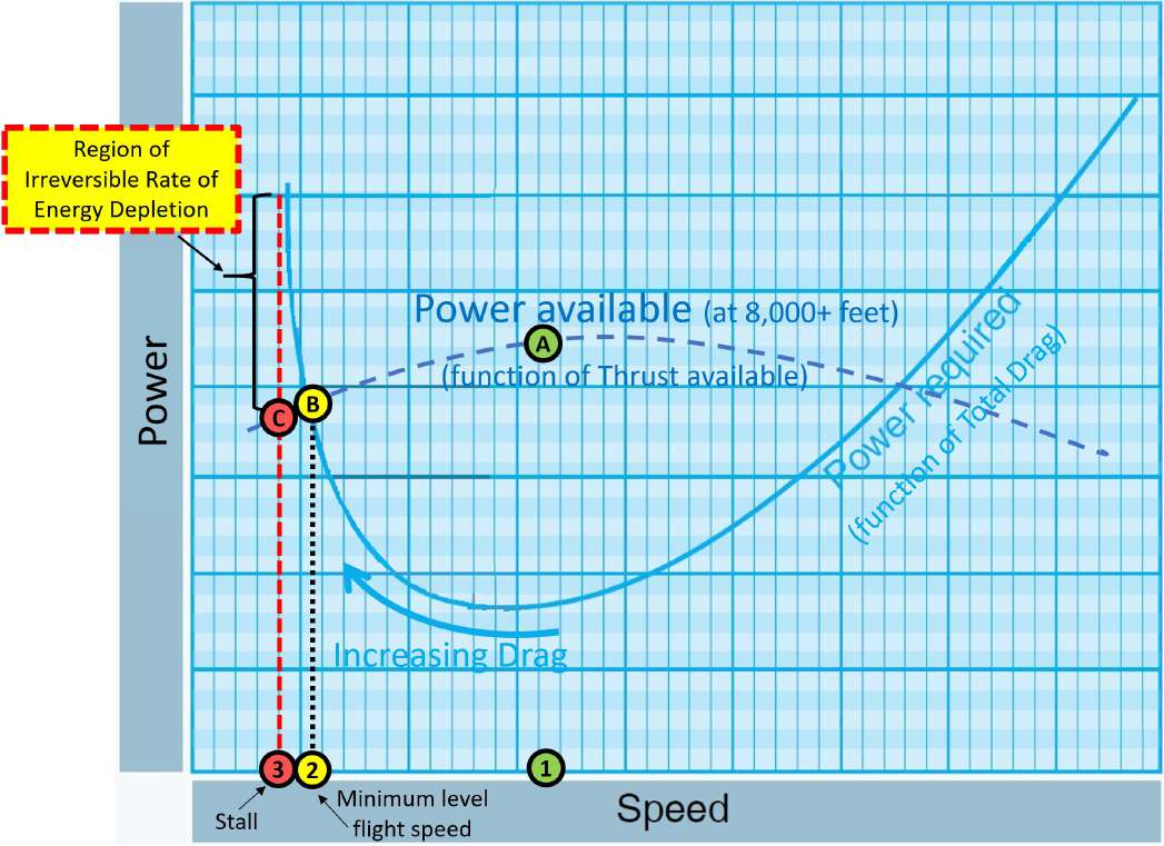
1.
A pilot of a normally
-
aspirated, twin-engine airplane departs out of Rocky Mountain Metropolitan airport
(KBJC) in the morning on a nice summer day and flies into Aspen/Pitkin County airport (KASE).
2.
The pilot enjoys the scenery around Aspen, eats lunch, and decides to return home in the early hot
afternoon.
3.
The pilot departs KASE off of runway 33. At full throttle/power the airplane takes longer to accelerate but
rotates at the normal speed.
4.
The pilot pitches to the normal pitch target, retracts the gear, and initiates a climb.
5.
The pilot notices the airplane isn’t performing as desired. The pilot checks to see if the gear is up and
adjusts the mixtures to try and get a little more power.
6.
The terrain is rising, the pilot gradually pitches up, and the airplane starts losing airspeed.
7.
The airplane quits climbing.
8.
The stall horn begins to sound.
The above scenario is hypothetical, but there have been very similar situations that have ended tragically.
The airplane in the above scenario has encountered an unintended deceleration and impending sink rate that could rapidly become
irreversible. This can be shown in two ways, using the traditional power curve
[Figure 4-14]
and the energy map
[Figure 4-15]
:
Figure 4-14.
The energy depletion scenario viewed in the power required and available curve. Compared with the power available
curve depicted in Figure 4-4, note the lower power available curve at this high elevation (7,820 feet at the departure airport) and
higher density altitude than standard during a hot afternoon.
4-15
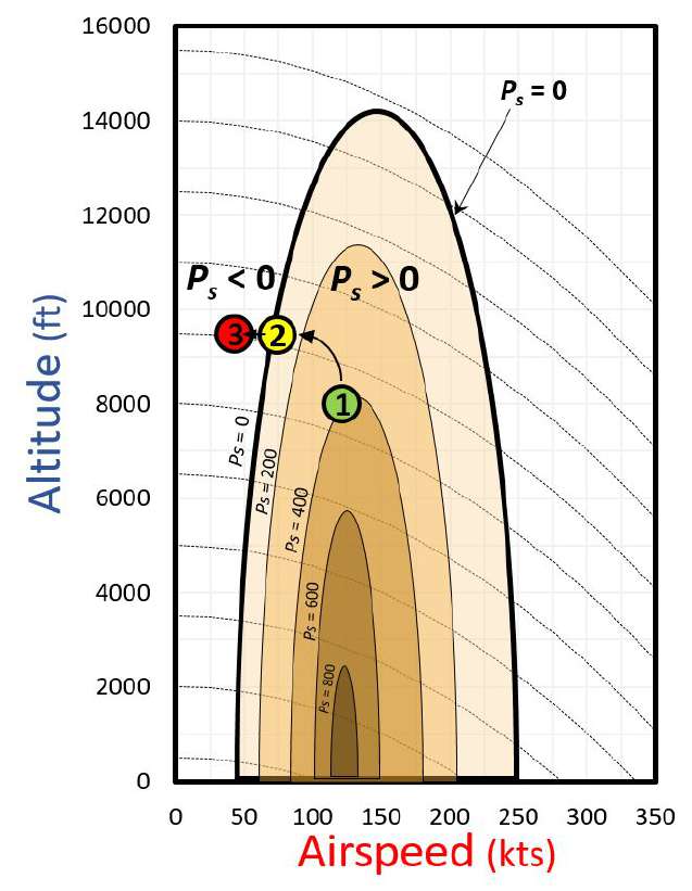
As illustrated in the airplane's power required and available curves
[Figure 4-14]
, the airplane slows down, going from speed 1 where
it is climbing (A: power available greater than power required), to speed 2, where it stops climbing (B: power available equal to
power required), and continuing to speed 3 where the stall horn sounds (C: power available less than power required). The
energy map
[Figure 4-15]
tells the same story from a total mechanical energy standpoint: the airplane has positive
P
S
at point 1 and
climbs to point 2 where it stops climbing since
P
S
= 0
, then continues to point 3, where the
P
S
< 0
and the stall horn sounds.
Figure 4-15.
The energy depletion scenario viewed in the energy map. Specific excess power (P
S
) contours are labeled in units of feet
per minute.
The question then is: what does the pilot do to recover from this predicament? The answer is proper energy management. The
airplane needs to move to a different place on the energy map that will allow the airplane to begin climbing. So, what does that mean?
⦁
As can be seen in
Figure 4-12
, the pilot is in a scenario akin to that at the desired altitude, but with
cautions when very slow.
⦁
The pilot then has to do something that is not intuitive; consider gaining speed at the expense of some
altitude initially to improve climbing performance with full
throttle
.
⦁
Once the airplane accelerates to an airspeed in which the
P
S
> 0
, it can begin to climb again.
The above recovery scenario is shown in the energy map
Figure 4-16,
which illustrates the important role of the elevator in
assisting the pilot to recover from unintentional and dangerous decelerati
o
n and/or sink rate (refer to
Additional Role for the Elevator
section).
4-16
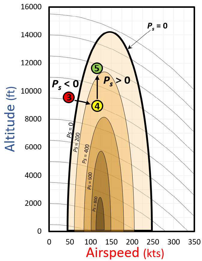
T
he airplane needs to gain speed at the expense of some altitude, moving from point 3 where the
P
S
< 0
to point 4 where the
P
S
> 0
.
The airplane can then initiate a constant airspeed climb to point 5, at the desired target altitude and airspeed
[Figure 4-16]
. Note that
the desired target climb airspeed in the presence of rising terrain may be
V
X
, the speed for best angle of climb.
V
X
is slightly slower
than
V
Y
, the speed for best rate of climb, and will result in a lower climb rate but steepest climb angle. Once the airplane has
recovered from the unintentional airspeed loss and begins climbing at
V
X
, the pilot should assess the situation and make an important
decision to mitigate further risk—either continue climbing or do something else. Should the airplane not have the needed
performance to safely clear the rising terrain on its intended course, the pilot has at least another available option: make a 180
degree turn and return to land at the departure airport until temperature and density altitude conditions improve.
Figure 4-16.
The energy loss scenario recovery viewed in the energy map. Specific excess power (P
S
) contours are labeled in units of
feet per minute.
The above rising terrain scenario is just one example illustrating the risk of irreversible deceleration and/or sink rate. Pilots need to be
aware that unintentional depletion of mechanical energy can happen in various instances, especially as the airplane approaches
the slow edge of its energy envelope at low altitude, where available specific excess power (
P
S
) is zero. Examples include unstable/
slow approaches to landing; high-drag go-arounds where the pilot neglects to raise the gear and/or flaps; and steeper-than-normal
turns in the traffic pattern. Note that irreversible sink rates do not necessarily involve exceeding the critical AOA resulting in a stall
and spin. The airplane can be unstalled and still experience unrecoverable sink rates near the high
-
speed edge of its energy
envelope, where available specific excess power (
P
S
) is also zero. Two examples are high
-
speed steep spirals following botched steep
level turns, and high
-
speed dives too close to the ground.
The bottom line? Should the airplane ever experience unintended excessive negative energy rates with little or no excess power
available under a given flight condition, the pilot needs to use proper energy management allowing a prompt recovery and a suitable
follow-up action.
4-17
Review of Terms and Definitions
The terms and definitions specific to this chapter appear below.
Aircraft Energy Management
The process
of
planning,
monitoring
and
controlling
altitude and
airspeed
targets in
relation
to
the airplane’s
energy
state.
Note that
this definition is concerned with managing mechanical energy (altitude and airspeed) and addresses the safety (flight control) side of
energy management. It does not address the efficiency (aircraft performance) side of energy management, which is concerned with
how efficiently the engine generates mechanical energy from fuel and how efficiently the airframe spends that energy in flight.
Energy System
A flying airplane is an
open
energy system. That means that the airplane can gain energy from some source (e.g.
,
fuel) and lose
energy to the environment (e.g.
,
surrounding air). In addition, energy can be added to or removed from the airplane’s total mechanical
energy stored as altitude and airspeed.
Total Mechanical Energy
Sum of the energy in altitude (potential energy) and the energy in airspeed (kinetic energy).
Kinetic Energy
Amount of energy due to the airspeed, expressed as
½mV²
, where
m
= airplane’s mass, and
V
= airspeed.
Potential Energy
Amount of energy due to the altitude, expressed as
mgh
, where
m
= airplane’s mass,
g
= gravitational constant, and
h
= altitude.
Energy State
The airplane’s total mechanical energy and its distribution between altitude and airspeed.
Energy Exchange
Trading one form of energy (e.g.
,
altitude) for another form (e.g.
,
airspeed).
Energy Balance Equation
According to this equation, the net transfer of mechanical energy into and out of the airplane (a function of thrust minus drag) is
always equal to the change in its total mechanical energy (a function of altitude and airspeed). Note that this simplified definition does
not account for long-term changes in total mechanical energy caused by the reduction in aircraft weight as fuel is gradually burned in
flight.
Power Available
The airplane’s rate of energy gain due to maximum available engine thrust at a given airspeed. Expressed as
TV
, where
T
=
engine thrust and
V
= airspeed. Usually measured in horsepower, foot-pound per minute, or foot-pound per second.
Power Required
The airplane’s rate of energy loss due to total drag at a given airspeed. Expressed as
DV
, where
D
= total drag and
V
= airspeed.
Usually measured in horsepower, foot-pound per minute, or foot-pound per second.
Specific Excess Power (
P
S
)
Measured in feet per minute or feet per second, it represents rate of energy change—the ability of an airplane to climb or accelerate
from a given flight condition. Available specific excess power is found by dividing the difference between power available and power
required
by
the airplane’s
weight.
4-18
Energy Height or Total Specific Energy (
E
S
)
Measured in units of height (e.g.
,
feet), it represents the airplane’s total energy per unit weight. It is found by dividing the sum
of potential energy and kinetic energy by the airplane’s weight. It also represents the maximum height that an airplane would reach
from its current altitude, if it were to trade all its speed for altitude.
Energy Erro
r
An
altitude and/or
airspeed
deviation
from
an
intended
target expressed
in
terms
of
energy.
Depending
on
the airplane’s
total
amount
of energy and its distribution between altitude and airspeed, energy errors are classified as total energy errors, energy distribution
errors, or a combination of both errors.
Total Energy Error
An energy error where the total amount of mechanical energy is not correct. The airplane has too much or too little total energy
relative to the intended altitude-speed profile. When this error occurs, the pilot will observe that altitude and airspeed deviate in the
same
direction (e.g.
,
higher and faster than desired; or lower and slower than desired). An example would be an airplane on
final approach that is above the desired glide slope and at a faster airspeed than desired.
Energy Distribution Error
An energy error where the total mechanical energy is correct, but the distribution between potential (altitude) and kinetic energy
(airspeed) is not correct relative to the intended altitude-speed profile. When this error occurs, the pilot will observe that altitude and
airspeed deviate in
opposite
directions (e.g.
,
higher and slower than desired; or lower and faster than desired). An example would be
an airplane on final approach that is above the desired glide slope and at a slower airspeed than desired.
Irreversible Deceleration and/or Sink Rate
Unrecoverable depletion of mechanical energy as a result of continuous loss of airspeed and/or altitude coupled with insufficient
excess power available under a given flight condition. Failure to recover above a certain critical AGL altitude results in the airplane
hitting the ground regardless of what the pilot does.
Chapter Summary
Every pilot is an energy manager—managing energy in the form of altitude and airspeed from takeoff to landing. Proper energy
management is essential for performing any maneuver as well as for attaining and maintaining desired vertical flightpath and airspeed
profiles in everyday flying. It is also critical to flight safety since mistakes in managing energy state can contribute to loss of control
inflight (LOC-I), controlled flight into terrain (CFIT)
,
and approach and landing accidents. The objectives of this chapter are for pilots
to: 1) gain an understanding of basic energy management concepts; 2) learn the energy role of the controls for managing the
airplane’s energy state; and 3) develop the ability to identify, assess
,
and mitigate risks associated with failure to manage the airplane’s
energy state.
4-19
Airplane Flying Handbook (FAA-H-8083-3C)
Chapter 5: Maintaining Aircraft Control: Upset Prevention and Recovery
Training
Introduction
Safe pilots prevent loss of control in flight (LOC-I), which is the leading cause of fatal general aviation accidents in the U.S. and
commercial aviation worldwide. LOC-I includes any significant deviation of an aircraft from the intended flightpath and it often
results from an airplane upset. Maneuvering represents the most common phase of flight for general aviation LOC-I accidents;
however, LOC-I accidents occur in all phases of flight.
To prevent LOC-I accidents, it is important for pilots to recognize and maintain a heightened awareness of situations that increase the
risk of loss of control. Those situations include: uncoordinated flight, equipment malfunctions, pilot complacency,
distraction, turbulence, and poor risk management. Attempting to fly in instrument meteorological conditions (IMC) when the
pilot is not qualified or proficient is a common example of poor risk management. The
Emergency Procedures
chapter of this
handbook contains specific information regarding unintended flight into IMC. Sadly, there are also LOC-I accidents resulting from
intentional disregard for safety.
To maintain aircraft control when faced with these or other contributing factors, the pilot needs to be aware of situations where LOC-I
can occur; recognize when an airplane is approaching a stall, has stalled, or is in an upset condition; and understand and execute the
correct procedures to recover the aircraft.
Defining an Airplane Upset
The term “upset” was formally introduced by an industry work group in 2004 in the “Pilot Guide to Airplane Upset Recovery,” which
is a part of the “Airplane Upset Recovery Training Aid.” The work group was primarily focused on large transport airplanes and
sought to come up with one term to describe an “unusual attitude” or “loss of control,” for example, and to generally describe specific
parameters as part of its definition. Consistent with the Guide, the FAA considers an upset to be
an
event that unintentionally
exceeds the parameters normally experienced in flight or training. These parameters are:
1.
Pitch attitude greater than 25°, nose up
2.
Pitch attitude greater than 10°, nose down
3.
Bank angle greater than 45°
4.
Within the above parameters, but flying at airspeeds inappropriate for the conditions
The reference to inappropriate airspeeds describes a number of undesired aircraft states, including stalls. However, stalls are directly
related to angle of attack (AOA), not airspeed.
To develop the crucial skills to prevent LOC-I, a pilot may receive academic or on-aircraft upset prevention and recovery training
(UPRT), which should include: slow flight, stalls, spins, and unusual attitudes.
Upset training places considerable emphasis on understanding and preventing an upset, so a pilot avoids such a situation. If an upset
does occur, upset training also reinforces proper recovery techniques. A detailed discussion of UPRT follows, including core
concepts, what the training should include, and what airplanes or kinds of simulation can be used for the training. A discussion
of various maneuvers and how to execute them follows later in this chapter.
Upset Prevention and Recovery
An unusual attitude is commonly referenced as an unintended or unexpected attitude in instrument flight. These unusual attitudes are
introduced to a pilot during student pilot training as part of basic attitude instrument flying and continue to be trained and tested as
part of certification for an instrument rating, aircraft type rating, and an airline transport pilot certificate. A pilot is taught the
conditions or situations that could cause an unusual attitude, with focus on how to recognize one, and how to recover from one.
Unusual Attitudes Versus Upsets
Given the upset definition, there are a few key distinctions between an unusual attitude and an upset. An upset:
5-1
⦁
Includes stall events.
⦁
Includes overspeeds or other inappropriate speeds for a given flight condition.
⦁
Has defined parameters. For example, for training purposes an instructor could place the aircraft in a 30°
bank with a nose-up pitch attitude of 15° and ask the student to recover and that would be considered an
unusual attitude, but would not meet the upset parameters.
⦁
Centers on unintentional situations that may lead to a startle effect. For example, during unusual attitude
training, the pilot is often directed to close their eyes, and any element of surprise disappears.
The top four causal and contributing factors that have led to an upset and resulted in LOC-I accidents are:
1. Environmental factors
2. Mechanical factors
3. Human factors
4. Stall-related factors
Environmental Factors
Turbulence, or a large variation in wind velocity over a short distance, can cause upset and LOC-I. Maintain awareness of conditions
that can lead to various types of turbulence, such as clear air turbulence, mountain waves, wind shear, and thunderstorms or
microbursts. In addition to environmentally-induced turbulence, wake turbulence from other aircraft can lead to upset and LOC-I.
Icing can destroy the smooth flow of air over the airfoil and increase drag while decreasing the ability of the airfoil to create lift.
Therefore, it can significantly degrade airplane performance, resulting in a stall if not handled correctly.
Mechanical Factors
Modern airplanes and equipment are very reliable, but anomalies do occur. Some of these mechanical failures can directly cause a
departure from normal flight, such as asymmetrical flaps, malfunctioning or binding flight controls, and runaway trim.
Upsets can also occur if there is a malfunction or misuse of the autoflight system. Advanced automation may tend to mask the cause
of the anomaly. Disengaging the autopilot and the autothrottles allows the pilot to directly control the airplane and possibly eliminate
the cause of the problem. For these reasons the pilot should maintain proficiency to manually fly the airplane in all flight conditions
without the use of the autopilot/autothrottles.
Although these and other in-flight anomalies may not be preventable, knowledge of systems and AFM/POH recommended
procedures helps the pilot minimize their impact and prevent an upset. In the case of instrument failures, avoiding an upset and
subsequent LOC-I
may
depend
on
the pilot’s
proficiency
in
the use of
secondary
instrumentation
and
partial panel operations.
Human Factors
VMC to IMC
Unfortunately, accident reports indicate that continued VFR flight from visual meteorological conditions (VMC) into marginal VMC
and IMC is a factor contributing to LOC-I. A loss of the natural horizon substantially increases the chances of encountering vertigo or
spatial disorientation, which can lead to upset.
IMC
When operating in IMC, maintain awareness of conditions.
Diversion of Attention
In addition to its direct impact, an in-flight anomaly
or
malfunction
can
also
lead
to
an
upset if
it diverts
the pilot’s
attention
from
basic airplane control responsibilities. Failing to monitor the automated systems, over-reliance on those systems, or incomplete
knowledge and experience with those systems can lead to an upset. Diversion of attention can also occur simply from the pilot’s
efforts to set avionics or navigation equipment while flying the airplane.
5-2
Task Saturation
The margin of safety is the difference between task requirements and pilot capabilities. An upset and eventual LOC-I can occur
whenever requirements exceed capabilities. For example, an airplane upset event that requires rolling an airplane from a near-inverted
to an upright orientation may demand piloting skills beyond those learned during primary training. In another example, a fatigued
pilot who inadvertently encounters IMC at night coupled with a vacuum pump failure, or a pilot fails to engage pitot heat while flying
in IMC, could become disoriented and lose control of the airplane due to the demands of extended—and unpracticed—partial panel
flight. Additionally, unnecessary low-altitude flying and impromptu demonstrations for friends or others on the ground could lead
pilots to exceed their capabilities, with fatal results.
Sensory Overload/Deprivation
A
pilot’s
ability
to
adequately
correlate
warnings,
annunciations,
instrument indications,
and
other
cues from
the airplane during an
upset can be limited. Pilots faced with upset situations can be rapidly confronted with multiple or simultaneous visual, auditory, and
tactile warnings. Conversely, sometimes expected warnings are not provided when they should be; this situation can distract a pilot as
much as multiple warnings can.
The ability to separate time-critical information from distractions takes practice, experience, and knowledge of the airplane and its
systems. Cross-checks are necessary not only to corroborate other information that has been presented, but also to determine if
information might be missing or invalid. For example, a stall warning system may fail and therefore not warn a pilot of close
proximity to a stall, so other cues need to be used to avert a stall and possible LOC-I. These cues include aerodynamic buffet, loss of
roll authority, or inability to arrest a descent.
Spatial Disorientation
Spatial disorientation has been a significant factor in many airplane upset accidents. Accident data from 2008 to 2013 shows nearly
200 accidents associated with spatial disorientation with more than 70% of those being fatal. All pilots are susceptible to false sensory
illusions while flying at night or in certain weather conditions. These illusions can lead to a conflict between actual attitude
indications and what the pilot senses is the correct attitude. Disoriented pilots may not always be aware of their orientation error.
Many airplane upsets occur while the pilot is engaged in some task that takes attention away from the flight instruments or outside
references. Others perceive a conflict between bodily senses and the flight instruments, and allow the airplane to divert from the
desired flightpath because they cannot resolve the conflict.
A pilot may experience spatial disorientation or perceive the situation in one of three ways:
1. Recognized spatial disorientation: the pilot recognizes the developing upset or the upset condition and is
able to safely correct the situation.
2. Unrecognized spatial disorientation: the pilot is unaware that an upset event is developing, or has occurred,
and fails to make essential decisions or take any corrective action to prevent LOC-I.
3. Incapacitating spatial disorientation: the pilot is unable to affect a recovery due to some combination of:
(a) not understanding the events as they are unfolding, (b) lacking the skills required to alleviate or correct
the situation, or (c) exceeding psychological or physiological ability to cope with what is happening.
For detailed information regarding causal factors of spatial disorientation, refer to Aerospace Medicine Spatial Disorientation and
Aerospace Medicine Reference Collection, which provides spatial disorientation videos. The videos are available online at:
www.faa.gov/about/office_org/headquarters_offices/avs/offices/aam/cami/library/online_libraries/aerospace_medicine/sd/videos/
.
Surprise and Startle Response
Surprise is
an
unexpected
event that violates a pilot’s
expectations
and
can
affect the mental processes used
to
respond
to
the event.
Startle is an uncontrollable, automatic muscle reflex, raised heart rate, blood pressure, etc., elicited by exposure to a sudden, intense
event that violates a
pilot’s
expectations.
This human response to unexpected events has traditionally been underestimated or even ignored during flight training. The reality is
that untrained pilots often experience a state of surprise or a startle response to an airplane upset event. Startle may or may not lead to
surprise. Pilots can protect themselves against a debilitating surprise reaction or startle response through scenario-based training, and
in such training, instructors can incorporate realistic distractions to help provoke startle or surprise. To be effective the controlled
training
scenarios
should
have a perception
of
risk
or
threat of
consequences
sufficient to
elevate the pilot’s
stress
levels. Such
scenarios can help prepare a pilot to mitigate psychological/physiological reactions to an actual upset.
5-3
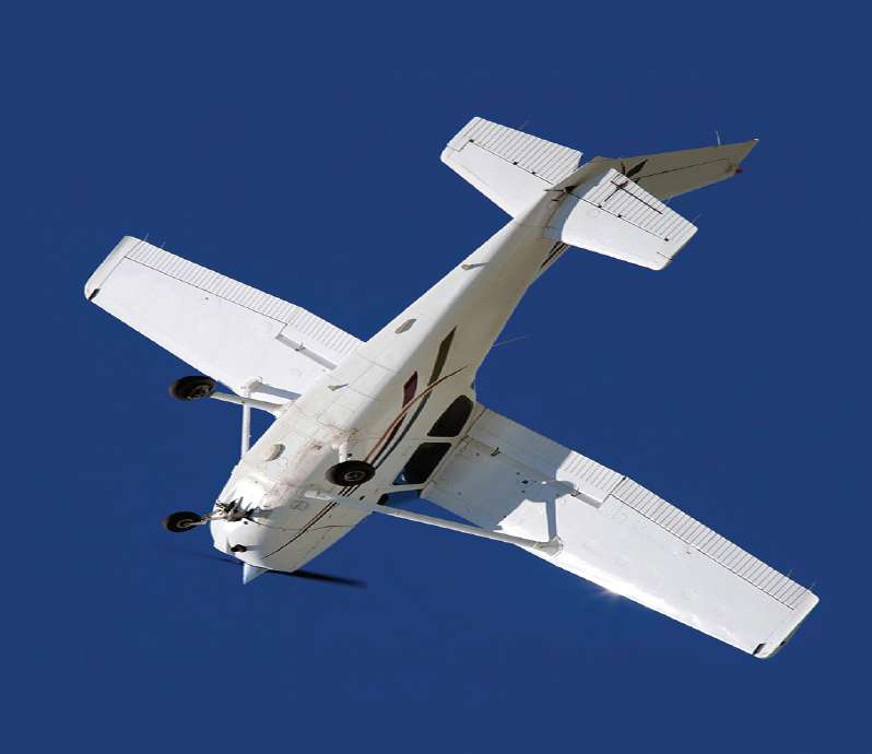
Upset Prevention and Recovery Training (UPRT)
Upsets are not intentional flight maneuvers, except in maneuver-based training; therefore, they are often unexpected. The reaction of
an inexperienced or inadequately trained pilot to an unexpected abnormal flight attitude is usually instinctive rather than intelligent
and deliberate. Such a pilot often reacts with abrupt muscular effort, which is without purpose and even hazardous in turbulent
conditions, at excessive speeds, or at low altitudes.
Without proper upset recovery training on interpretation and airplane control, the pilot can quickly aggravate an abnormal flight
attitude into a potentially fatal LOC-I accident. Consequently, UPRT is intended to focus education and training on the prevention of
upsets, and on recovering from these events if they occur.
[Figure 5-1]
Figure 5-1.
Maneuvers that better prepare a pilot for understanding unusual attitudes and situations are representative of upset
training.
⦁
Upset prevention refers to pilot actions to avoid a divergence from the desired airplane state.
Awareness and prevention training serve to avoid incidents. Early recognition of an upset scenario
coupled with appropriate preventive action often can mitigate a situation that could otherwise
escalate into an LOC-I accident.
⦁
Recovery refers to pilot actions that return an airplane that is diverging in altitude, airspeed, or
attitude to a desired state from a developing or fully-developed upset. Recovery training serves to
reduce accidents as a result of an unavoidable or inadvertently-encountered upset event. The pilot
can learn to initiate a recovery to a normal flight mode immediately upon recognition of the
developing upset condition. The pilot should ensure that control inputs and power adjustments
applied to counter an upset are in direct proportion to the amount and rates of change of roll, yaw,
and pitch, or airspeed so as to avoid overstressing the airplane unless ground contact is imminent.
5-4
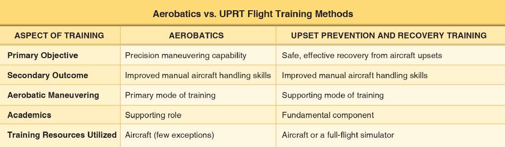
UPRT Training Core Concepts
Airplane upsets are by nature time-critical events; they can also place pilots in unusual and unfamiliar attitudes that sometimes require
counterintuitive control movements. Upsets have the potential to put a pilot into a life-threatening situation compounded by panic,
diminished mental capacity, and potentially incapacitating spatial disorientation. Real-world upset situations often provide very little
time to react, but exposure to such events during training can reduce surprise and mitigate confusion during an actual unexpected
upset. The goal is to equip the pilot to promptly recognize an escalating threat pattern or sensory overload and quickly identify and
correct an impending upset.
UPRT stresses that the first step is recognizing any time the airplane begins to diverge from the intended flightpath or airspeed. Pilots
need to identify and determine what, if any, action should be taken. As a general rule, any time visual cues or instrument indications
differ from basic flight maneuver expectations, the pilot should assume an upset and cross-check to confirm the attitude, instrument
error or instrument malfunction.
To achieve maximum effect, it is crucial for UPRT concepts to be conveyed accurately and in a non-threatening manner. Reinforcing
concepts
through
positive experiences
significantly
improves a pilot’s
depth
of
understanding,
retention
of
skills,
and
desire for
continued training. Also, training in a carefully structured environment allows for exposure to these events and can help the pilot react
more quickly, decisively, and calmly when the unexpected occurs during flight. However, like many other skills, the skills needed for
upset prevention and recovery are perishable and thus require continuous reinforcement through training.
UPRT in the airplane and flight simulation training device (FSTD) should be conducted in both visual and simulated instrument
conditions to allow pilots to practice recognition and recovery under both situations. UPRT should allow them to experience and
recognize some of the physiological factors related to each, such as the confusion and disorientation that can result from visual cues
in
an
upset event. Training
that includes recovery
from
bank
angles exceeding
90
degrees
could
further
add
to
a pilot’s
overall
knowledge and skills for upset recognition and recovery. For such training, additional measures should be taken to ensure the
suitability of the airplane or FSTD and that instructors are appropriately qualified.
Upset prevention and recovery training is different from aerobatic training.
[Figure 5-2]
In aerobatic training, the pilot knows and
expects the maneuver, so effects of startle or surprise are missing. The main goal of aerobatic training is to teach pilots how to
intentionally and precisely maneuver an aerobatic-capable airplane in three dimensions. The primary goal of UPRT is to help pilots
overcome sudden onsets of stress to avoid, prevent, and recover from unplanned excursions that could lead to LOC-I.
Figure 5-2.
Some differences between aerobatic training and upset prevention and recovery training.
Comprehensive UPRT builds on three mutually supportive components: academics, airplane-based training and, typically at the
transport category type-rating training level, use of FSTDs. Each has unique benefits and limitations but, when implemented
cohesively and comprehensively throughout a pilot’s career, the components can offer maximum preparation for upset awareness,
prevention, recognition, and recovery.
Academic Material (Knowledge and Risk Management)
Academics establish the foundation for development of situational awareness, insight, knowledge, and skills. As in practical skill
development, academic preparation should move from the general to specific while emphasizing the significance of each basic
concept. Although academic preparation is crucial and does offer a level of mitigation of the LOC-I threat, long-term retention of
knowledge is best achieved when applied and correlated with practical hands-on experience.
The academic portion of UPRT should also address the prevention concepts surrounding aeronautical-decision making (ADM) and
risk management (RM), and proportional counter response.
5-5
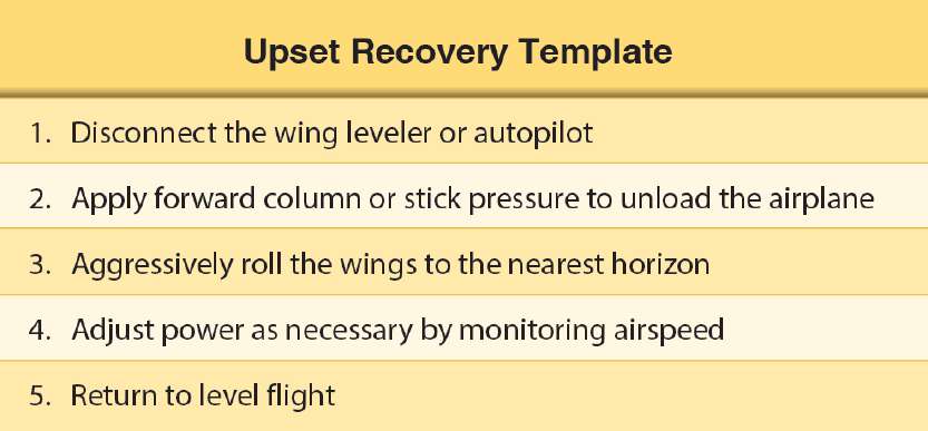
Prevention Through ADM and Risk Management
This element of prevention routinely occurs in a time scale of minutes or hours, revolving around the concept of effective ADM and
risk management through analysis, awareness, resource management, and interrupting the error chain through basic airmanship skills
and sound judgment. For instance, imagine a situation in which a pilot assesses conditions at an airport prior to descent and
recognizes those conditions as being too severe to safely land the airplane. Using situational awareness to avert a potentially
threatening flight condition is an example of prevention of an LOC-I situation through effective risk management. Pilots should
evaluate the circumstances for each flight (including the equipment and environment), looking specifically for scenarios that may
require a higher level of risk management. These include situations that could result in low-altitude maneuvering, steep turns in the
pattern, uncoordinated flight, or increased load factors.
Another part of ADM is crew resource management (CRM) or single-pilot resource management (SRM). Both are relevant to the
UPRT environment. When available, a coordinated crew response to potential and developing upsets can provide added benefits such
as increased situational awareness, mutual support, and an improved margin of safety. Since an untrained crewmember can be the
most unpredictable element in an upset scenario, initial UPRT for crew operations should be mastered individually before being
integrated into a multi-crew, CRM environment. A crew should be able to accomplish the following:
1.
Communicate and confirm the situation clearly and concisely;
2.
Transfer control to the most situationally-aware crewmember;
3.
Using standardized interactions, work as a team to enhance awareness, manage stress, and mitigate fear.
Prevention Through Proportional Counter-Response
In simple terms, proportional counter-response is the timely manipulation of flight controls and thrust, either as the sole pilot or crew
as the situation dictates, to manage an airplane flight attitude or flight envelope excursion that was unintended or not commanded by
the pilot.
The time-scale of this element of prevention typically occurs on the order of seconds or fractions of seconds, with the goal being the
ability to recognize a developing upset and take proportionally-appropriate avoidance actions to preclude the airplane entering a
fully-developed upset. Due to the sudden, surprising nature of this level of developing upset, there exists a high risk for panic and
overreaction to ensue and aggravate the situation.
Recovery
Last but not least, the academics portion lays the foundation for development of UPRT skills by instilling the knowledge, procedures,
and techniques required to accomplish a safe recovery. The airplane and FSTD-based training elements presented below serve to
translate the academic material into structured practice. This can start with classroom visualization of recovery procedures and
continue with repetitive skill practiced in an airplane, and then potentially further developed in the simulated environment.
In the event looking outside does not provide enough situational awareness of the airplane attitude, a pilot can use the flight
instruments to recognize and recover from an upset. To recover from nose-high and nose-low attitudes, the pilot should follow the
procedures recommended in the AFM/POH. In general, upset recovery procedures are summarized in
Figure 5-3.
Figure 5-3.
Upset recovery template.
5-6
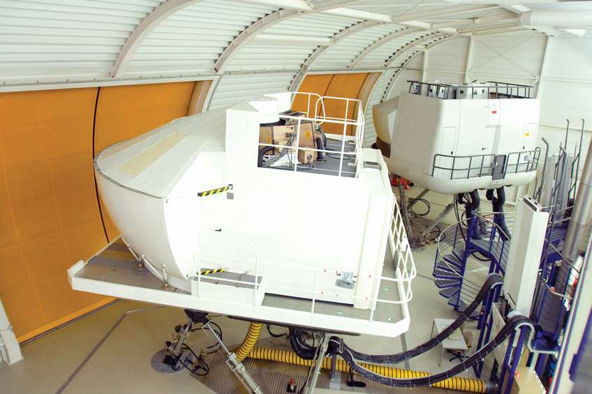
Common Errors
Common errors associated with upset recoveries include the following:
1. Incorrect assessment of what kind of upset the airplane is in
2. Failure to disconnect the wing leveler or autopilot
3. Failure to unload the airplane, if necessary
4. Failure to roll in the correct direction
5. Inappropriate management of the airspeed during the recovery
Roles of FSTDs and Airplanes in UPRT
Training devices range from aviation training devices (e.g., basic and advanced) to FSTDs (e.g., flight training devices (FTD) and full
flight simulators (FFS)) and have a broad range of capabilities. While all of these devices have limitations relative to actual flight,
only the higher fidelity devices (i.e., Level C and D FFS) are a satisfactory substitution for developing UPRT skills in the actual
aircraft. Except for these higher fidelity devices, initial skill development should be accomplished in a suitable airplane, and the
accompanying training device should be used to build upon these skills.
[Figure 5-4]
Figure 5-4.
A Level D full-flight simulator could be used for UPRT.
Airplane-Based UPRT
Ultimately, the more realistic the training scenario, the more indelible the learning experience. Although creating a visual scene of a
110° banked attitude with the nose 30° below the horizon may not be technically difficult in a modern simulator, the learning
achieved while viewing that scene from the security of the simulator is not as complete as when viewing the same scene in
an airplane. Maximum learning is achieved when the pilot is placed in the controlled, yet adrenaline-enhanced, environment of
upsets experienced while in flight. For these reasons, airplane-based UPRT improves a pilot’s ability to overcome fear in an airplane
upset event.
However, airplane-based UPRT does have limitations. The level of upset training possible may be limited by the maneuvers approved
for the particular airplane, as well as by the flight instructor’s own UPRT capabilities. For instance, UPRT conducted in the
normal
category by a typical flight instructor will necessarily be different from UPRT conducted in the aerobatic category by a flight
instructor with expertise in aerobatics.
5-7
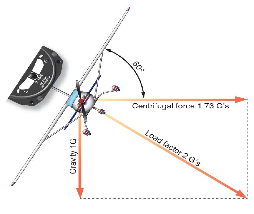
When considering upset training conducted in an aerobatic-capable airplane in particular, the importance of employing instructors
with specialized UPRT experience in those airplanes cannot be overemphasized. Just as instrument or tailwheel instruction requires
specific skill sets for those operations, UPRT demands that instructors possess the competence to oversee trainee progress, and the
ability to intervene as necessary with consistency and professionalism. As in any area of training, the improper delivery of stall, spin,
and upset recovery training often results in negative learning, which could have severe consequences not only during the
training itself, but in the skills and mindset pilots take with them when they have passengers and place the lives of others at stake.
All-Attitude/All-Envelope Flight Training Methods
Sound UPRT encompasses operation in a wide range of possible flight attitudes and covers the airplane’s limit flight envelope. This
training is essential to prepare pilots for unexpected upsets. As stated at the outset, the primary focus of a comprehensive
UPRT program is the avoidance of, and safe recovery from, upsets. Much like basic instrument skills, which can be applied to flying
a vast array of airplanes, the majority of skills and techniques required for upset recovery are not airplane-specific. Just as basic
instrument skills learned in lighter and lower performing airplanes are applied to more advanced airplanes, basic upset recovery
techniques provide lessons that remain with pilots throughout their flying careers.
FSTD–based UPRT
UPRT can be effective in high fidelity devices (i.e., Level C and D FFS); however, instructors and pilots should be mindful of the
technical and physiological boundaries when using a particular FSTD for upset training. This training is a current requirement for
pilots seeking a multiengine airplane ATP certificate in accordance with 14 CFR part 61, section 61.156, and the training course must
be FAA approved.
Coordinated Flight
Coordinated flight occurs whenever the pilot is proactively correcting for yaw effects associated with power (engine/
propeller effects), aileron inputs, how an airplane reacts when turning, and airplane rigging. The airplane is in coordinated flight
when the airplane’s nose is yawed directly into the relative wind and the ball is centered in the slip/skid indicator (except
for certain multiengine airplane operation with an engine failure).
[Figure 5-5]
Figure 5-5.
Coordinated flight in a turn.
5-8
Angle of Attack
The angle of attack (AOA) is the angle at which the chord of the wing meets the relative wind. The chord is a straight line from the
leading edge to the trailing edge. At low angles of attack, the airflow over the top of the wing flows smoothly and produces lift with a
relatively small amount of drag. As the AOA increases, lift as well as drag increases; however, above a wing’s critical AOA, the flow
of air separates from the upper surface and backfills, burbles, and eddies, which reduces lift and increases drag. This condition is a
stall, which can lead to loss of control if the AOA is not reduced.
It is important for the pilot to understand that a stall is the result of exceeding the critical AOA, not of insufficient airspeed. The term
“stalling speed” can be misleading, as this speed is often discussed when assuming 1G flight at a particular weight and configuration.
Increased load factor directly affects stall speed (as well as do other factors such as gross weight, center of gravity, and flap setting).
Therefore, it is possible to stall the wing at any airspeed, at any flight attitude, and at any power setting. For example, if a
pilot maintains airspeed and rolls into a coordinated, level 60° banked turn, the load factor is 2G, and the airplane will stall at a speed
that is 41 percent higher than the 1G stall speed. In that 2G level turn, the pilot has to increase AOA to increase the lift
required to maintain altitude. At this condition, the pilot is closer to the critical AOA than during level flight and therefore closer
to the higher stalling
speed. Because “stalling speed” is not a constant number, pilots need to understand the underlying factors
that affect it in order to maintain aircraft control in all circumstances.
Slow Flight
Flying at reduced airspeeds is normal in the takeoff/departure and approach/landing phases of flight. While pilots typically perform
these operations at low airspeeds and close to the ground, pilots learn to maneuver an airplane in slow flight at a safe altitude. During
slow flight, any further increase in angle of attack, increase in load factor, or reduction in power, will result in a stall warning (e.g.,
aircraft buffet, stall horn, etc.), and pilots should react to and correct for any stall indication. Note that stall training builds upon the
knowledge and skill acquired from the slow flight maneuver and encompasses the period of time from the stall warning (e.g., aircraft
buffet, stall horn, etc.) to the stall.
The objective of maneuvering in slow flight is to develop the pilot’s ability to fly at low speeds and high AOAs. Through practice, the
pilot becomes familiar with the feel, sound, and visual cues of flight in this regime, where there is a degraded response to
control inputs and where it is more difficult to maintain a selected altitude. It is essential that pilots:
1. understand the aerodynamics associated with slow flight in various aircraft configurations and attitudes,
2. recognize airplane cues in these flight conditions,
3. smoothly manage coordinated flight control inputs while maneuvering without a stall warning, and
4. make prompt appropriate correction should a stall warning occur.
For pilot training and testing purposes, slow flight includes two main elements:
⦁
Slowing to, maneuvering at, and recovering from an airspeed at which the airplane is still capable of
maintaining controlled flight without activating the stall warning—5 to 10 knots above the 1G stall
speed is a good target.
⦁
Performing slow flight in configurations appropriate to takeoffs, climbs, descents, approaches to
landing, and go-arounds.
Slow flight should be introduced with the target airspeed sufficiently above the stall to permit safe maneuvering, but close enough to
the stall warning for the pilot to experience the characteristics of flight at a low airspeed. One way to determine the target airspeed is
to slow the aircraft to the stall warning when in the desired slow flight configuration, pitch the nose down slightly to eliminate the
stall warning, and add power to maintain altitude and note the airspeed.
When practicing slow flight, a pilot learns to divide attention between aircraft control and other demands. How the airplane feels at
the slower airspeeds demonstrates that as airspeed decreases, control effectiveness decreases. For instance, reducing airspeed from
30 knots to 20 knots above the stalling speed will result in a certain loss of effectiveness of flight control inputs because of less
airflow over the control surfaces. As airspeed is further reduced, the control effectiveness is further reduced and the reduced airflow
over the control surfaces results in larger control movements being required to create the same response. Pilots sometimes refer to the
feel of
this
reduced
effectiveness
as “sloppy” or
“mushy” controls.
5-9
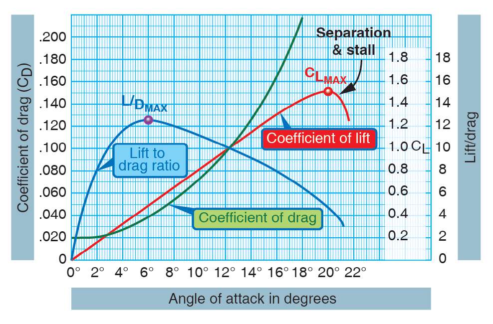
When flying above the minimum drag speed (L/D
MAX
), more power is required to fly even faster. When flying at speeds below
L/D
MAX
, more power is required to fly even slower. Since slow flight will be performed well below L/D
MAX
, the pilot should be aware
that large power inputs or a reduction in AOA will be required to prevent the aircraft from decelerating. It is important to note that
when flying below L/D
MAX
or
on the backside of the power curve
, as the AOA increases toward the critical AOA and the
airplane’s speed continues to decrease, small changes in the pitch control result in disproportionally large changes in induced drag
and therefore changes in airspeed. As a result, pitch becomes a more effective control of airspeed when flying below L/D
MAX
and
power is an effective control of the path.
It is also important to note that an airplane flying below L/D
MAX
, exhibits a characteristic known as “speed instability” and
the
airspeed will continue to decay without appropriate pilot action. For example, if the airplane is disturbed by turbulence and the
airspeed decreases, the airspeed may continue to decrease without the appropriate pilot action of reducing the AOA or adding power.
[Figure 5-6]
Figure 5-6.
Angle-of-attack in degrees.
Performing the Slow Flight Maneuver
Slow flight training includes:
⦁
Slowing the airplane smoothly and promptly from cruising to approach speeds without changes in altitude
or heading, while
increasing the angle of attack and
setting the required power and trim.
⦁
Configuration changes, such as extending the landing gear and adding flaps, while maintaining heading and
altitude.
⦁
Turning while maintaining altitude.
⦁
Straight-ahead climbs and climbing medium-banked (approximately 20 degrees) turns, and straight-ahead
power-off gliding descents and descending turns, which represent the takeoff and landing phases of flight.
Slow flight in a single-engine airplane should be conducted so the maneuver can be completed no lower than 1,500 feet AGL (3,000
for multiengine airplanes), or higher, if recommended by the manufacturer. In all cases, practicing slow flight should be conducted at
an adequate height above the ground for recovery should the airplane inadvertently stall.
5-10
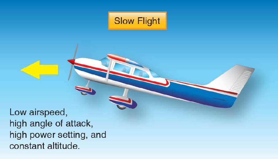
To begin the slow flight maneuver, the pilot should clear the area and gradually reduce thrust from cruise power and adjust the pitch
to allow the airspeed to decrease while maintaining altitude. As the speed of the airplane decreases, there is a change in the sound of
the airflow. As the speed approaches the target slow flight speed, which is an airspeed just above the stall warning in the desired
configuration (i.e., approximately 5–10 knots above the stall speed for that flight condition), additional power will be needed to
maintain altitude. During these changing flight conditions, the pilot should trim the airplane to compensate for changes in control
pressures. If the airplane remains trimmed at the pre-maneuver cruising speed, strong aft (back) control pressure is needed on the
elevator, which will make precise control difficult.
Slow flight is typically performed and evaluated in the landing configuration. Therefore, both the landing gear and the flaps should be
extended to the landing position, as applicable. It is recommended the prescribed before-landing checks be completed to configure
the airplane. The extension of gear and flaps typically occurs once cruise power has been reduced and at appropriate airspeeds to
ensure limitations for extending those devices are not exceeded. Practicing this maneuver in other configurations, such as a clean or
takeoff configuration, is also good training and may be evaluated on the practical test.
With an AOA just under the AOA which may cause an aerodynamic buffet or stall warning, the flight controls are less effective.
[Figure 5-7]
The elevator control is less responsive and larger control movements are necessary to retain control of the airplane. In
propeller-driven airplanes, torque, slipstream effect, and P-factor may produce a strong left yaw, which requires right rudder input to
maintain coordinated flight. The closer the airplane is to the 1G stall, the greater the amount of right rudder pressure required.
Figure 5-7.
Slow flight—low airspeed, high angle of attack, high power, and constant altitude.
Maneuvering in Slow Flight
When the desired pitch attitude and airspeed have been established in straight-and-level slow flight, the pilot needs to maintain
awareness of outside references and continually cross-check
the airplane’s
instruments
to
maintain
control. The pilot should
note the
feel of the flight controls, especially the airspeed changes caused by small pitch adjustments, and the altitude changes caused by
power
changes. The pilot should
practice turns
to
determine the airplane’s
controllability
characteristics
at this
low
speed.
During the
turns, it will be necessary to increase power to maintain altitude. Abrupt or rough control movements during slow flight may result in
a stall. For instance, abruptly raising the flaps while in slow flight can cause the plane to stall.
The pilot should also practice climbs and descents by adjusting the power when stabilized in straight-and-level slow flight. The pilot
should note the increased yawing tendency at high power settings and counter it with rudder input as needed.
To exit the slow flight maneuver, add power. As airspeed and lift increase, apply forward control pressure to reduce the AOA and
maintain altitude. Maintain coordinated flight, level the wings as necessary, and return to the desired flightpath. As airspeed increases,
clean up the airplane by retracting flaps and landing gear, if they were extended, and adjust trim as needed. A pilot should anticipate
the changes to the AOA as the landing gear and flaps are retracted to avoid a stall.
5-11
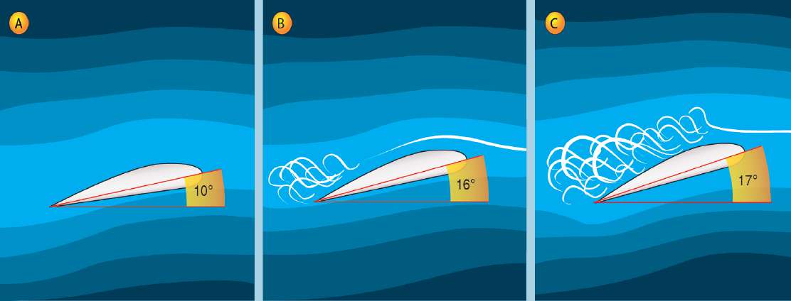
Common Errors
Common errors in the performance of slow flight are:
1. Failure to adequately clear the area
2. Inadequate back-elevator pressure as power is reduced, resulting in altitude loss
3. Excessive back-elevator pressure as power is reduced, resulting in a climb followed by rapid reduction in airspeed
4. Insufficient right rudder to compensate for left yaw
5. Fixation on the flight instruments
6. Failure to anticipate changes in AOA as flaps are extended or retracted
7. Inadequate power management
8. Inability to adequately divide attention between airplane control and orientation
9. Failure to properly trim the airplane
10. Failure to respond to a stall warning
Stalls
A
stall is
an
aerodynamic condition
which
occurs
when
smooth
airflow
over
the airplane’s
wings
is
disrupted,
resulting
in
loss of lift.
Specifically, a stall occurs when the AOA—the angle between the chord line of the wing and the relative wind—exceeds
the wing’s
critical AOA. It is possible to exceed the critical AOA at any airspeed, at any attitude, and at any power setting.
[Figure 5-8]
Figure 5-8.
Critical angle of attack and stall.
For these reasons, it is important to understand factors and situations that can lead to a stall, and develop proficiency in stall
recognition and recovery. Performing intentional stalls will familiarize the pilot with the conditions that result in a stall, assist in
recognition of an impending stall, and develop the proper corrective response if a stall occurs. Stalls are practiced to two different
levels:
⦁
Impending Stall—an impending stall occurs when the AOA causes a stall warning, but has not yet reached
the critical AOA. Indications of an impending stall can include buffeting, stick shaker, or aural warning.
⦁
Full Stall—a full stall occurs when the critical AOA is exceeded. Indications of a full stall are typically that
an uncommanded nose down pitch cannot be readily arrested, and may be accompanied by an uncommanded
rolling motion. For airplanes equipped with stick pushers, their activation is also an indicator of a full stall.
Although it depends on the degree to which a stall has progressed, some loss of altitude is expected during recovery. The longer it
takes for the pilot to recognize an impending stall, the more likely it is that a full stall will result. Intentional stalls should therefore be
performed at an altitude that provides adequate height above the ground for recovery and return to normal level flight.
5-12
Stall Recognition
A pilot should recognize the flight conditions that are conducive to stalls and know how to apply the necessary corrective action. This
level of proficiency involves learning to recognize an impending stall by sight, sound, and feel.
Stalls are usually accompanied by a continuous stall warning for airplanes equipped with stall warning devices. These devices
may include an aural alert, lights, or a stick shaker all which alert the pilot when approaching the critical AOA. Most vintage
airplanes, and many types of light-sport and experimental airplanes, do not have stall warning devices installed. However,
certification standards permit manufacturers to provide the required stall warning either through the inherent aerodynamic qualities of
the airplane (pre-stall buffeting) or through a stall warning device that gives a clear indication of the impending stall.
Other sensory cues for the pilot include:
⦁
Feel—the pilot will feel control pressures change as speed is reduced. With progressively less resistance
on the control surfaces, the pilot needs to use larger control movements to get the desired airplane
response.
The pilot will notice the airplane’s
reaction
time to
control movement increases.
⦁
Vision—since the airplane can be stalled in any attitude, vision is not a foolproof indicator of an impending
stall. However, maintaining pitch awareness is important.
⦁
Hearing—as speed decreases, the pilot should notice a change in sound made by the air flowing along the
airplane structure.
⦁
Kinesthesia—the physical sensation
(sometimes referred
to
as “seat of
the pants” sensations)
of
changes in
direction or speed is an important indicator to the trained and experienced pilot in visual flight. If this
sensitivity is properly developed, it can warn the pilot of an impending stall.
Pilots should remember that a level-flight 1G published stalling speed is valid only:
1.
In unaccelerated 1G flight
2.
In coordinated flight (slip-skid indicator centered)
3.
At one weight (typically maximum gross weight)
4.
At a particular center of gravity (CG) (typically maximum forward CG)
Angle of Attack Indicators
An AOA indicator gives the pilot better situational awareness pertaining to the aerodynamic health of the airfoil. This can be referred
to as stall margin awareness or knowing the existing margin between the current AOA and the critical AOA. While learning to
recognize stalls without relying on stall warning devices is important, an AOA indicator provides an additional visual indication of
the airplane’s proximity to the critical AOA. The FAA along with the General Aviation Joint Steering Committee (GAJSC) is
promoting the use of Angle of Attack (AOA) indicators to reduce the occurrence of loss of control in flight.
Without an AOA indicator, the AOA is “invisible” to pilots. These devices measure several parameters simultaneously and determine
the current angle of attack providing a visual image to the pilot of the current AOA along with representation of the proximity to the
critical AOA. These devices can give a visual representation of the energy management state of the airplane. The energy state of an
airplane is the balance between airspeed, altitude, drag, and thrust and represents how efficiently the airfoil is operating. With this
increased situational awareness pertaining to the energy condition of the airplane, the pilot has additional information to help prevent a
loss of control scenario.
AOA indicators are increasingly affordable for GA airplanes. There are several different kinds of AOA indicators with varying
methods for calculating AOA; therefore, proper installation and training on the use of these devices is important. AOA indicators
measure several parameters simultaneously, determine the current AOA, and provide a visual image of the proximity to the critical
AOA.
[Figure 5-9]
Some AOA indicators also provide aural indications, which can provide awareness to a change in AOA that is
trending towards the critical AOA prior to installed stall warning systems. It’s important to note that some indicators take flap
position into consideration, but not all do.
While AOA indicators provide a simple visual representation of the current AOA and its proximity to the critical AOA, they are not
without their limitations. These limitations should be understood by operators of GA airplanes equipped with these devices. Like
advanced automation such as autopilots and moving maps, the misunderstanding or misuse of the equipment can have disastrous
results. Some items that may limit the effectiveness of an AOA indicator are listed below:
5-13
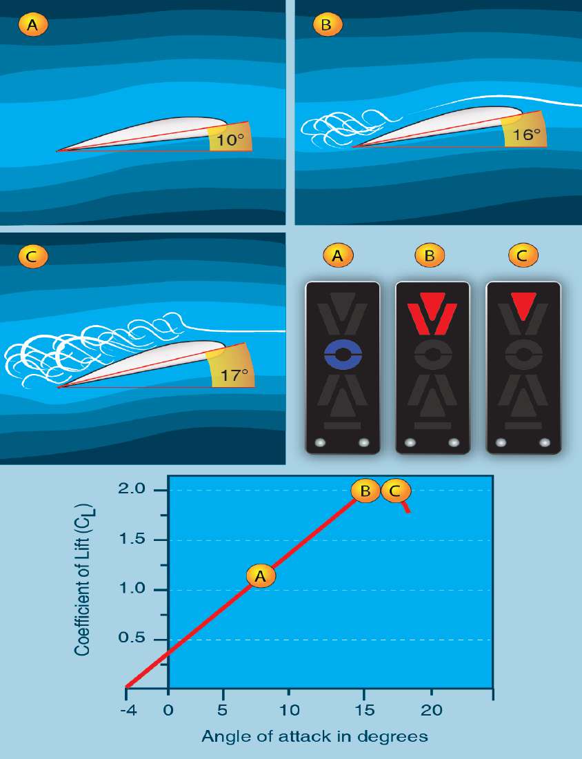
1. Calibration techniques
2. Probes or vanes not being heated
3. The type of indicator itself
4. Flap setting
5. Wing contamination
Figure 5-9.
A conceptual representation of an AOA indicator. It is important to become familiar with the equipment installed in a
specific airplane.
Installation of AOA indicators not required by type certification in GA airplanes has been streamlined by the FAA. The FAA
established policy in February 2014 pertaining to non-required AOA systems and how they may be installed as a minor alteration,
depending upon their installation requirements and operational utilization, and the procedures to follow for certification of these
installations. For updated information on this, please reference the FAA website at
www.faa.gov
.
5-14
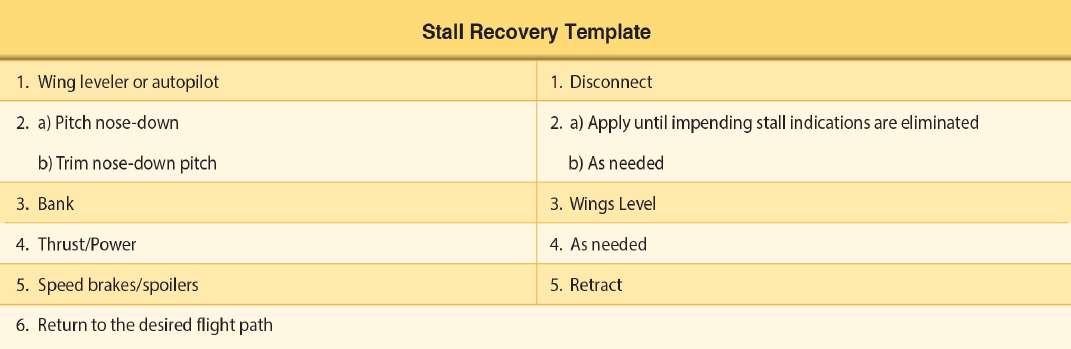
If airplane equipment includes an angle of attack indicator, the pilot should know how the particular device determines AOA, what
the display indicates, and the appropriate response to any indication. Pilots are encouraged to conduct in-flight training to see the
indications throughout various maneuvers, such as slow flight, stalls, takeoffs, and landings, and to practice the appropriate responses
to those indications. It is also important to note that some items may limit the effectiveness of an AOA indicator (e.g., calibration
techniques, wing contamination, unheated probes/vanes). Pilots flying an airplane equipped with an AOA indicator should refer to the
pilot handbook information or contact the manufacturer for specific limitations applicable to that indicator type.
Ground and flight instructors should make every attempt to receive training from an instructor knowledgeable about AOA indicators
prior to giving instruction pertaining to or in airplanes equipped with an AOA indicator. Pilot schools should incorporate training on
AOA indicators in their syllabi whether their training aircraft are equipped with them or not.
Stall Characteristics
Different airplane designs can result in different stall characteristics. The pilot should know the stall characteristics of the airplane
being
flown
and
the manufacturer’s
recommended
recovery
procedures. Factors
that can
affect the stall characteristics
of
an
airplane
include its geometry, CG, wing design, and high-lift devices. Engineering design variations make it impossible to specifically
describe the stall characteristics for all airplanes; however, there are enough similarities in small general aviation training-type
airplanes to offer broad guidelines.
Most training airplanes are designed so that the wings stall progressively outward from the wing roots (where the wing attaches to the
fuselage) to the wingtips. Some wings are manufactured with a certain amount of twist, known as washout, resulting in the outboard
portion of the wings having a slightly lower AOA than the wing roots. This design feature causes the wingtips to have a smaller AOA
during flight than the wing roots. Thus, the wing roots of an airplane exceed the critical AOA before the wingtips, meaning the wing
roots stall first. Therefore, when the airplane is in a stalled condition, the ailerons should still have a degree of control effectiveness
until/unless stalled airflow migrates outward along the wings. Although airflow may still be attached at the wingtips, a pilot should
exercise caution using the ailerons prior to the reduction of the AOA because it can exacerbate the stalled condition. For example, if
the airplane rolls
left at the stall (“rolls-off”),
and
the pilot applies
right aileron
to
try
to
level the wing,
the downward-deflected
aileron on the left wing produces a greater AOA (and more induced drag), and a more complete stall at the tip as the critical AOA is
exceeded. This can cause the wing to roll even more to the left, which is why it is important to first reduce the AOA before attempting
to roll the airplane.
The pilot should also understand how the factors that affect stalls are interrelated. In a power-off stall, for instance, the cues
(buffeting, shaking) are less noticeable than in the power-on stall. In the power-off, 1G stall, the predominant cue may be the elevator
control position (full up elevator against the stops) and a high descent rate.
Fundamentals of Stall Recovery
Depending on the complexity of the airplane, stall recovery could consist of as many as six steps. Even so, the pilot should remember
the most important action to an impending stall or a full stall is to reduce the AOA. There have been numerous situations where pilots
did not first reduce AOA, and instead prioritized power and maintaining altitude, which resulted in a loss of control. This section
provides a generic stall recovery procedure for light general aviation aircraft adapted from a template developed by major airplane
manufacturers and can be adjusted appropriately for the aircraft used.
[Figure 5-10]
However, a pilot should always follow the
aircraft-specific manufacturer’s
recommended
procedures if
published
and
current.
Figure 5-10.
Stall recovery template.
5-15
The recovery actions should be made in a procedural manner; they can be summarized in
Figure 5-10.
The following discussion
explains each of the six steps:
1. Disconnect the wing leveler or autopilot (if equipped). Manual control is essential to recovery in all
situations. Disconnecting this equipment should be done immediately and allow the pilot to move to the
next crucial step quickly. Leaving the wing leveler or autopilot connected may result in inadvertent
changes or adjustments to the flight controls or trim that may not be easily recognized or appropriate,
especially during high workload situations.
2. a) Pitch nose-down control. Reducing the AOA is crucial for all stall recoveries. Push forward on the
flight controls to reduce the AOA below the critical AOA until the impending stall indications are
eliminated before proceeding to the next step.
b) Trim nose-down pitch. If the elevator does not provide the needed response, pitch trim may be
necessary. However, excessive use of pitch trim may aggravate the condition, or may result in loss of
control or high structural loads.
3. Roll wings level. This orients the lift vector properly for an effective recovery. It is important not to be
tempted to control the bank angle prior to reducing AOA. Both roll stability and roll control will improve
considerably after getting the wings flying again. It is also imperative to proactively cancel yaw with proper
use of the rudder to prevent a stall from progressing into a spin.
4. Add thrust/power. Power should be added as needed, as stalls can occur at high power or low power
settings or at high airspeeds or low airspeeds. Advance the throttle promptly, but smoothly, as needed
while using rudder and elevator controls to stop any yawing motion and prevent any undesirable pitching
motion. Adding power typically reduces the loss of altitude during a stall recovery, but it does not
eliminate a stall. The reduction in AOA is imperative. For propeller-driven airplanes, power application
increases the airflow around the wing, assisting in stall recovery.
5. Retract speedbrakes/spoilers (if equipped). This will improve lift and the stall margin.
6. Return to the desired flightpath. Apply smooth and coordinated flight control movements to return
the airplane to the desired flightpath being careful to avoid a secondary stall. However, be
situationally aware of the proximity to terrain during the recovery and take the necessary flight
control action to avoid contact with it.
The above procedure can be adapted for the type of aircraft flown. For example, a single-engine training airplane without an autopilot
would likely only use four of the six steps. The first step is not applicable. The actual first step is the reduction of the AOA until the
stall warning is eliminated. Use of pitch trim is less of a concern in a training airplane because most pilots can overpower the trim in
these airplanes. Any improper trim can be corrected when returning to the desired flightpath. The next step is rolling the wings level
followed by the addition of power as needed all while maintaining coordinated flight. If the airplane is not equipped with speedbrakes
or spoilers, this step is also skipped. Returning to the desired flightpath concludes the recovery.
Similarly, a glider pilot does not have an autopilot; therefore, the first step is the reduction of AOA until the stall warning is
eliminated. The pilot would then roll wings level while maintaining coordinated flight. Since there is no power to add, this step would
not apply. Retracting speedbrakes or spoilers would be the next step for a glider pilot followed by returning to the desired flightpath.
Stall Training
Practice in both power-on and power-off stalls is important because it simulates stall conditions that could occur during normal flight
maneuvers. It is important for pilots to understand the possible flight scenarios in which a stall could occur. Stall accidents usually
result from an inadvertent stall at a low altitude, with the recovery not completed prior to ground contact. For example, power-on
stalls
are practiced
to
develop
the pilot’s
awareness
of
what could
happen
if
the airplane is
pitched
to
an
excessively
nose-high
attitude immediately after takeoff, during a climbing turn, or when trying to clear an obstacle. Power-off turning stalls develop the
pilot’s
awareness
of
what could
happen
if
the controls
are improperly
used
during
a turn
from
the base leg
to
the final approach. The
power-off straight-ahead stall simulates the stall that could occur when trying to stretch a glide after the engine has failed, or if low on
the approach to landing.
As in all maneuvers that involve significant changes in altitude or direction, the pilot should ensure that the area is clear of other air
traffic at and below their altitude and that sufficient altitude is available for a recovery before executing the maneuver. It is
recommended that stalls be practiced at an altitude that allows recovery no lower than 1,500 feet AGL for single-engine airplanes, or
higher if recommended by the AFM/POH. Losing altitude during recovery from a stall is to be expected.
5-16
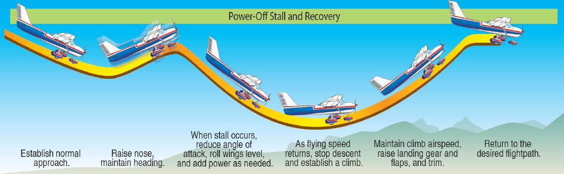
Approaches to Stalls (Impending Stalls), Power-On or Power-Off
An impending stall occurs when the airplane is approaching, but does not exceed the critical AOA. The purpose of practicing
impending stalls is to learn to retain or regain full control of the airplane immediately upon recognizing that it is nearing a stall, or
that a stall is likely to occur if the pilot does not take appropriate action. Pilot training should emphasize teaching the same recovery
technique for impending stalls and full stalls.
The practice of impending stalls is of particular value in developing the pilot’s sense of feel for executing maneuvers in which
maximum airplane performance is required. These maneuvers require flight in which the airplane approaches a stall, but the pilot
initiates recovery at the first indication, such as by a stall warning device activation.
Impending stalls may be entered and performed in the same attitudes and configurations as the full stalls or other maneuvers
described in this chapter. However, instead of allowing the airplane to reach the critical AOA, the pilot should immediately reduce
AOA once the stall warning device goes off, if installed, or recognizes other cues such as buffeting. The pilot should hold the nose-
down control input as required to eliminate the stall warning. Then level the wings maintain coordinated flight, and then apply
whatever additional power is necessary to return to the desired flightpath. The pilot will have recovered once the airplane has returned
to the desired flightpath with sufficient airspeed and adequate flight control effectiveness and no stall warning. Performance of the
impending stall maneuver is unsatisfactory if a full stall occurs, if an excessively low pitch attitude is attained, or if the pilot fails to
take timely action to avoid excessive airspeed, excessive loss of altitude, or a spin.
Full Stalls, Power-Off
The practice of power-off stalls is usually performed with normal landing approach conditions to simulate an accidental stall
occurring during approach to landing. However, power-off stalls should be practiced at all flap settings to ensure familiarity with
handling arising from mechanical failures, icing, or other abnormal situations. Airspeed in excess of the normal approach speed
should not be carried into a stall entry since it could result in an abnormally nose-high attitude.
To set up the entry for a straight-ahead power-off stall, airplanes equipped with flaps or retractable landing gear should be in the
landing configuration. After extending the landing gear, applying carburetor heat (if applicable), and retarding the throttle
sufficiently, the pilot holds the airplane at a constant altitude until the airspeed decelerates to normal approach speed. The airplane
should then be smoothly pitched down to a normal approach attitude to maintain that airspeed. Wing flaps should be extended and
pitch attitude adjusted to maintain the airspeed. Once in a normal approach, the pilot sets the power to idle.
When the approach attitude and airspeed have stabilized, the pilot should smoothly raise the airplane’s nose to an attitude that induces
a stall. Directional control should be maintained and wings held level by coordinated use of the ailerons and rudder. Once the airplane
reaches an attitude that will lead to a stall, the pitch attitude is maintained with the elevator until the stall occurs. The stall is
recognized by the full-stall cues previously described.
Recovery from the stall is accomplished by reducing the AOA, applying as much nose-down control input as required to eliminate the
stall warning, leveling the wings, maintaining coordinated flight, and then applying power as needed. Right rudder pressure may be
necessary to overcome the engine torque effects as power is advanced and the nose is being lowered.
[Figure 5-11]
If simulating an
inadvertent stall on approach to landing, the pilot should initiate a go-around by establishing a positive rate of climb. Once in a climb,
the flaps and landing gear should be retracted as necessary.
Figure 5-11.
Power-off stall and recovery.
5-17
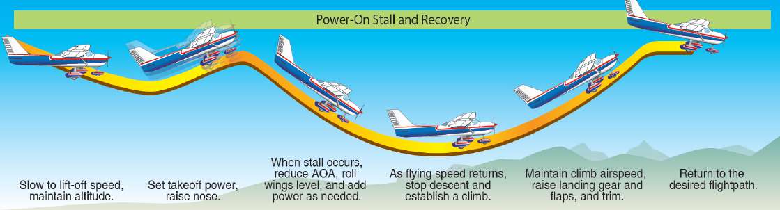
Recovery from power-off stalls should also be practiced from shallow banked turns to simulate an inadvertent stall during a turn from
base leg to final approach. During the practice of these stalls, the pilot should take care to ensure that the airplane remains
coordinated and the turn continues at a constant bank angle until the full stall occurs. If the airplane is allowed to slip, the outer wing
may stall first and move downward abruptly. In a skid, the bank angle may increase further to a potentially dangerous attitude. The
recovery procedure is the same, regardless of whether one wing rolls off first. The pilot should apply as much nose-down control
input as necessary to eliminate the stall warning, level the wings with ailerons, coordinate with rudder, and add power as needed. In
the practice of turning stalls, no attempt should be made to stall or recover the airplane on a predetermined heading. However, to
simulate a turn from base to final approach, the stall normally should be made to occur within a heading change of approximately 90°.
Full Stalls, Power-On
Power-on stall recoveries are practiced from straight climbs and climbing turns (15° to 20° bank) to help the pilot recognize the
potential for an accidental stall during takeoff, go around, climb, or when trying to clear an obstacle. Airplanes equipped with flaps or
retractable landing gear should normally be in the takeoff configuration; however, power-on stalls should also be practiced with the
airplane in a clean configuration (flaps and gear retracted) to ensure practice with all possible takeoff and climb configurations. When
practicing takeoff stall recovery, the airplane should be at maximum power, although for some airplanes it may be reduced to a setting
that will prevent an excessively high pitch attitude.
To set up the entry for power-on stalls, the pilot establishes the airplane in the takeoff or climb configuration and slows the airplane to
normal lift-off speed while continuing to clear the area of other traffic. Upon reaching the desired speed, the pilot sets takeoff power
or the recommended climb power for the power-on stall (often referred to as a departure stall) while establishing a climb attitude. The
purpose of reducing the airspeed to lift-off airspeed before the throttle is advanced to the recommended setting is to avoid an
excessively steep nose-up attitude for a long period before the airplane stalls.
After establishing the climb attitude, the pilot should smoothly raise the nose to increase the AOA, and hold that attitude until the full
stall occurs. As described in connection with the stall characteristics discussion, continual adjustments should be made to aileron
pressure, elevator pressure, and rudder pressure to maintain coordinated flight while holding the attitude until the full stall occurs. In
most airplanes, as the airspeed decreases the pilot should move the elevator control progressively further back while simultaneously
adding right rudder and maintaining the climb attitude until reaching the full stall.
The pilot should recognize when the stall has occurred and take action without delay to prevent a prolonged stalled condition. The
pilot should recover from the stall by immediately reducing the AOA and applying as much nose-down control input as required to
eliminate the stall warning, level the wings with ailerons, coordinate with rudder, and smoothly advance the power as needed. Since
the throttle is already at the climb power setting, this step may simply mean confirming the proper power setting.
[Figure 5-12]
Figure 5-12.
Power-on stall.
The final step is to return the airplane to the desired flightpath (e.g., straight and level or departure/climb attitude). With sufficient
airspeed and control effectiveness, the pilot may return the throttle to the appropriate power setting.
Secondary Stall
A secondary stall is so named because it occurs after recovery from a preceding stall. A normal recovery usually involves pointing the
nose of the airplane toward the ground. However, if a stall should occur at low altitude, the pilot's natural impulse is to bring the nose
up as soon as possible and to do so abruptly. This reaction is amplified as proximity to the ground increases. To demonstrate how this
occurs at altitude, the pilot makes an abrupt recovery after one stall and exceeds the critical AOA a second time. Note that this stall
may occur after any stall when the pilot does not sufficiently reduce the AOA by lowering the pitch attitude or attempts to break the
stall by using power only.
[Figure 5-13]
5-18
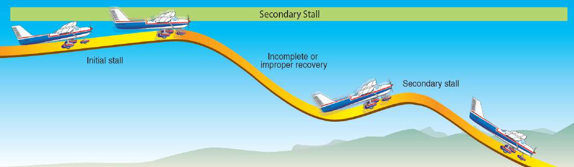
Figure 5-13.
Secondary stall.
If a secondary stall occurs, the pilot should again perform the stall recovery procedures by applying nose-down elevator pressure as
required to eliminate the stall warning, level the wings with ailerons, coordinate with rudder, and adjust power as needed. When the
airplane is no longer in a stalled condition the pilot can return the airplane to the desired flightpath. For pilot certification, this is a
demonstration-only maneuver. Only flight instructor applicants may be required to perform it on a practical test.
Accelerated Stalls
While pilots may understand the cause of an accelerated stall, it takes training to experience how these stalls develop and occur. The
objectives of demonstrating an accelerated stall are to determine the stall characteristics of the airplane, experience stalls at speeds
greater than the +1G stall speed, and develop the ability to instinctively recover at the onset of such stalls. This is a maneuver only
commercial pilot and flight instructor applicants may be required to perform or demonstrate on a practical test. However, all pilots
should be familiar with the situations that can cause an accelerated stall, how to recognize this type of stall, and how to execute the
appropriate recovery should one occur.
At the same gross weight, airplane configuration, CG location, power setting, and environmental conditions, a given airplane
consistently stalls at the same indicated airspeed provided the airplane is at +1G (i.e., steady-state unaccelerated flight). However, the
airplane can also stall at a higher indicated airspeed when the airplane is subject to an acceleration greater than +1G, such as when
turning, pulling up, or other abrupt changes in flightpath. Stalls encountered any time the G-load
exceeds
+1G are called
“accelerated
maneuver
stalls.”
The
accelerated
stall
would
most
frequently
occur
inadvertently
during
improperly
executed
turns,
stall
and
spin
recoveries, pullouts from steep dives, or when overshooting a base to final turn. An accelerated stall is typically demonstrated during
steep turns.
A pilot should never practice accelerated stalls with wing flaps in the extended position due to the lower design G-load limitations in
that configuration. Accelerated stalls should be performed with a bank of approximately 45°, and in no case at a speed greater than
the airplane manufacturer’s recommended airspeed, or the specified design maneuvering speed (V
A
) or operating maneuvering speed
(V
O
).
It is important to be familiar with V
A
or V
O
, how it relates to accelerated stalls, and how it changes depending on the airplane's
weight. V
A
is the maximum speed at which the positive design load limit can be imposed either by gusts or full one-sided deflection
with one control surface without causing structural damage.
V
O
is a historical operating limitation applicable to certain airplanes
only. It represents the maximum speed where, at any given weight, the pilot may apply full control excursion without exceeding the
design limit load factor.
Performing accelerated stalls at speeds up to the applicable V
A
or V
O
, ensures the airplane will reach the
critical AOA, which unloads the wing, before exceeding the design load limit. At speeds above V
A
or V
O
, the airplane can reach its
design load limit at less than the critical AOA. This condition makes it possible to add additional load and overstress the airplane.
Additional information on the effects of aircraft weight on stall speeds and structural limits while maneuvering is available in the
"Aerodynamics of Flight" chapter of the
Pilot’s
Handbook of Aeronautical Knowledge
(FAA-H-8083-25).
There are two methods for performing an accelerated stall. The most common accelerated stall procedure starts from straight-and-
level flight at an airspeed at or below V
A
or V
O
. The pilot rolls the airplane into a coordinated, level-flight 45° turn and then
smoothly, firmly, and progressively increase the AOA through back elevator pressure until a stall occurs. Alternatively, the pilot rolls
the airplane into a coordinated, level-flight 45° turn at an airspeed above V
A
or V
O
. After the airspeed slows to V
A
or V
O
, and at an
airspeed 5 to 10 percent faster than the unaccelerated stall speed, the pilot progressively increases the AOA through back elevator
pressure until a stall occurs. The increased back elevator pressure increases lift and the G load. The G load pushes the pilot’s
body
down in the seat. The increased lift also increases drag, which may cause the airspeed to decrease. The pilot should know the
published stall speed for 45° of bank, flaps up, before performing the maneuver. This speed is typically published in the AFM.
5-19