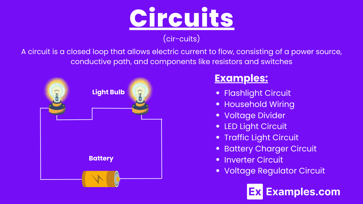
A circuit is a closed path through which electric current flows, composed of components like resistors, capacitors, and power sources. Kirchhoff’s Circuit Laws, including Kirchhoff’s First Law (current law) and Kirchhoff’s Second Law (voltage law), are essential for analyzing circuit behavior. Circuits are found in applications from household electronics to industrial machinery, controlling and directing electrical energy for various tasks.
What are Circuits?
Circuits are interconnected pathways that allow the flow of electric current, typically consisting of components like resistors, capacitors, inductors, and transistors. These elements are connected by conductive wires or traces through which electrons travel, creating a complete path for the current.
Examples of Circuits
- Simple Series Circuit A basic circuit with a single path for current, consisting of a battery, a resistor, and an LED connected end-to-end.
- Simple Parallel Circuit A circuit with multiple paths for current, consisting of a battery and two or more resistors connected across common points.
- Light Switch Circuit A household circuit where a switch controls the flow of current to a light bulb. When the switch is closed, the circuit is complete, and the light turns on.
- Battery-Powered Flashlight Circuit A circuit in a flashlight, where batteries provide power, a switch controls the flow, and a bulb emits light when the circuit is complete.
- Voltage Divider Circuit A circuit with two resistors in series, used to produce a specific voltage lower than the source voltage by dividing the input voltage.
- RC (Resistor-Capacitor) Circuit A circuit with a resistor and capacitor in series or parallel, used in timing applications like creating delays or filters in electronic devices.
- LC (Inductor-Capacitor) Circuit A circuit with an inductor and capacitor, often used in radio tuning circuits to select a specific frequency from a complex signal.
- Wheatstone Bridge Circuit A precise measurement circuit used to determine unknown resistances by balancing two legs of a bridge circuit.
- Operational Amplifier Circuit A circuit using an operational amplifier (op-amp) for various applications like signal amplification, filtering, or mathematical operations such as addition and integration.
- Digital Logic Circuit A circuit using logic gates (AND, OR, NOT, etc.) to perform logical operations, forming the basis of digital systems like computers and calculators.
- Pulse Width Modulation (PWM) Circuit A circuit used to control the power delivered to electrical devices by varying the duty cycle of a pulse signal, commonly used in motor speed control.
- Temperature Sensor Circuit A circuit using a thermistor (temperature-sensitive resistor) to monitor and respond to temperature changes, often used in thermostats.
- Transistor Amplifier Circuit A circuit using a transistor to amplify weak electrical signals, widely used in a and radio frequency amplification.
- Timer Circuit (555 Timer) A circuit using the 555 timer IC to generate precise time delays or oscillations, used in clocks, pulse generation, and LED flashers.
- Solar Cell Circuit A circuit that converts sunlight into electrical energy using solar cells, with components like diodes and batteries for storage and usage.
Types of Circuits
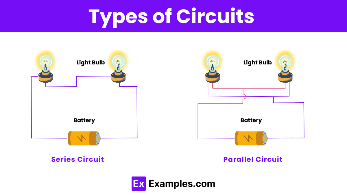
- Series Circuit: Components are connected end-to-end, forming a single path for current flow. In a series circuit, the same current flows through each component. Voltage is divided among the components based on their resistance (Ohm’s Law). Series circuits are simple to construct but can be problematic if one component fails, as it can break the entire circuit.
- Parallel Circuit: Components are connected across multiple paths, each having its own branch. Current divides among the branches based on their resistance. Each branch receives the same voltage (Kirchhoff’s Voltage Law). Parallel circuits offer redundancy, as the failure of one branch doesn’t affect others, and they allow for easier addition or removal of components. However, they can be complex to design and troubleshoot due to multiple paths.
- Series-Parallel Circuit: This type combines series and parallel configurations. Components may be grouped in series, and these groups are connected in parallel, or vice versa. Series-parallel circuits are commonly used in complex electrical networks where different loads require different configurations.
- Open Circuit: An open circuit has a break or gap, preventing current flow. Devices in the circuit won’t function until the circuit is closed.
- Closed Circuit: A closed circuit provides a complete path for current flow from the source through components and back to the source. It allows devices to operate normally as current can flow uninterrupted.
- AC Circuit: In alternating current (AC) circuits, the direction of current flow reverses periodically. AC circuits can be series, parallel, or a combination of both, similar to DC circuits. The behavior of components such as resistors, capacitors, and inductors in AC circuits can differ due to factors like impedance, reactance, and phase relationships. AC circuits are widely used in household electricity supply, electronics, and industrial applications due to the efficiency of power transmission over long distances.
Difference Between Series and Parallel Circuits
| Aspect | Series Circuit | Parallel Circuit |
|---|---|---|
| Connection | Components are connected end-to-end in a single path. | Components are connected across multiple paths. |
| Current | Same current flows through all components. | Current divides among branches based on their resistance. |
| Voltage | Voltage is divided among components based on resistance. | Each branch receives the same voltage. |
| Redundancy | No redundancy; failure of one component breaks the circuit. | Redundancy; failure of one branch does not affect others. |
| Ease of Addition | Difficult to add or remove components without affecting circuit. | Easier to add or remove components without affecting others. |
| Complexity | Simple in structure but complex if components fail. | Complex to design and troubleshoot due to multiple paths. |
| Applications | Used in simple circuits, like flashlights and decorations. | Used where redundancy or different voltages are needed, like household wiring. |
Rules of Circuits
Understanding circuits involves several fundamental rules that govern their behavior and operation. Here are the key rules for circuits:
- Ohm’s Law: This law relates the voltage (V), current (I), and resistance (R) in a circuit and states that V=I×R. It helps determine how voltage, current, and resistance interact within a circuit.
- Kirchhoff’s Current Law (KCL): KCL states that the total current entering a junction (or node) in a circuit is equal to the total current leaving the junction. In other words, the sum of currents entering a node equals the sum of currents leaving the node.
- Kirchhoff’s Voltage Law (KVL): KVL states that the sum of all voltages around any closed loop in a circuit is zero. It emphasizes the conservation of energy in electrical circuits.
- Series Circuit Rules:
- The total resistance in a series circuit is the sum of the individual resistances.
- The current through each component in a series circuit is the same.
- The total voltage across a series circuit is the sum of the individual voltages across each component.
- Parallel Circuit Rules:
- The total resistance of resistors in parallel is less than the smallest individual resistance.
- The voltage across each branch (parallel path) of a circuit is the same.
- The total current in a parallel circuit is the sum of the currents in each branch.
- Power in Circuits: The power (P) consumed by a circuit element can be calculated using P=V×I or P=I2×R or P=V2R, depending on the given parameters (voltage, current, resistance).
- Circuit Analysis Techniques:
- Mesh Analysis: Used to analyze circuits with multiple loops, applying KVL to each loop.
- Nodal Analysis: Used to analyze circuits with multiple nodes, applying KCL at each node.
FAQ’s
An electric circuit is a path through which electric current flows. It typically includes a power source, conductors, and components like resistors or capacitors.
Ohm’s Law states that the current through a conductor is directly proportional to the voltage across it and inversely proportional to the resistance, expressed as V=IR.
Basic components include a power source (battery), conductors (wires), and electrical elements like resistors, capacitors, switches, and LEDs.
A resistor is a component that limits the flow of electric current in a circuit, providing resistance measured in ohms (Ω).
A capacitor is a device that stores electrical energy in an electric field, used to smooth voltage fluctuations in circuits.
A short circuit occurs when a low-resistance path bypasses part of a circuit, causing excessive current flow, which can lead to damage or overheating.
A circuit breaker is a safety device that automatically interrupts the flow of electricity in a circuit when it detects an overload or short circuit.
A switch controls the flow of electricity in a circuit by opening (interrupting) or closing (completing) the electrical path.
Alternating current (AC) is an electric current that periodically reverses direction, commonly used in household power supplies.
Direct current (DC) is an electric current that flows in one direction, typically provided by batteries and used in electronic devices.