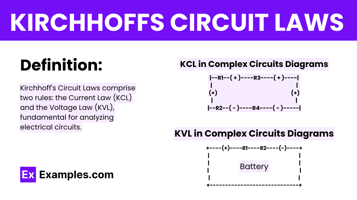
Kirchhoff’s Law
Kirchhoff’s First Law or Kirchhoff’s Current Law
Kirchhoff’s Current Law (KCL) is a fundamental principle in electrical engineering that describes the conservation of electric charge in a circuit. It states that the total current entering a junction (or node) in an electrical circuit is equal to the total current leaving the junction. KCL is based on the principle of charge conservation, where the amount of charge entering a region must equal the amount of charge leaving that region.
Formula
Mathematically, Kirchhoff’s Current Law can be expressed as:
This equation signifies that the algebraic sum of currents entering a junction is equal to the sum of currents leaving the junction. It can also be represented as:
Where:
𝐼ᵢₙ represents the currents entering the junction.
𝐼ₒᵤₜ represents the currents leaving the junction.
𝐼ₖ represents individual currents entering or leaving the junction, with inflows considered positive and outflows negative.
Circuit Diagrams
In circuit diagrams, a junction or node is represented by a point where multiple conductors meet. Conductors entering the junction are shown as lines leading into the point, while conductors leaving the junction are shown as lines leading away from the point.
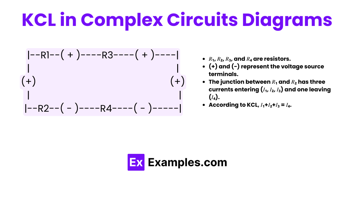
In this circuit:
- 𝑅₁, 𝑅₂, 𝑅₃, and 𝑅₄ are resistors.
- (+) and (−) represent the voltage source terminals.
- The junction between 𝑅₁ and 𝑅₂ has three currents entering (𝐼₁, 𝐼₂, 𝐼₃) and one leaving (𝐼₄).
- According to KCL, 𝐼₁+𝐼₂+𝐼₃ = 𝐼₄.
Kirchhoff’s Current Law provides a systematic method for analyzing complex electrical circuits, enabling engineers to determine unknown currents and voltages within the circuit.
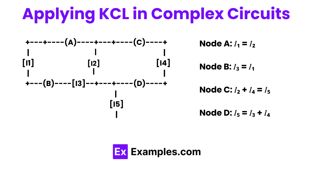
Applying KCL in Complex Circuits
For more complex circuits, KCL can be applied at each node separately. Here is an example where multiple nodes are involved:
Conclusion
KCL is essential for the analysis of any circuit, from the simplest to the most complex, as it provides a basis for determining the possible distribution of currents in a circuit. It ensures that all currents are accounted for, preventing any errors in calculations related to circuit behavior under various operating conditions. KCL is typically used alongside Kirchhoff’s Voltage Law (KVL) to analyze and solve circuit problems comprehensively.
Kirchhoff’s Second Law or Kirchhoff’s Voltage Law
Kirchhoff’s Voltage Law (KVL), also known as the second law, is a fundamental principle in the field of electrical engineering for analyzing closed loops in circuits. This law states that the algebraic sum of all voltages in a closed loop must be zero. This includes the sum of potential rises (voltage sources) and potential drops (resistive or reactive impedances) around any closed circuit path.
Formula
The mathematical expression of KVL is:
Here, 𝑉𝑘 represents the voltage drop or gain across each element in the loop.
Deep Explanation
Closed Loops: A closed loop is a complete path that returns to the starting point without crossing any node more than once. KVL is based on the law of conservation of
, which states that the total energy gained or lost in a loop must be zero.
Sign Convention: When applying KVL, you must follow a consistent sign convention. Typically, potential rises (voltage sources) are considered positive, and potential drops (such as across resistors, inductors, or capacitors) are considered negative.
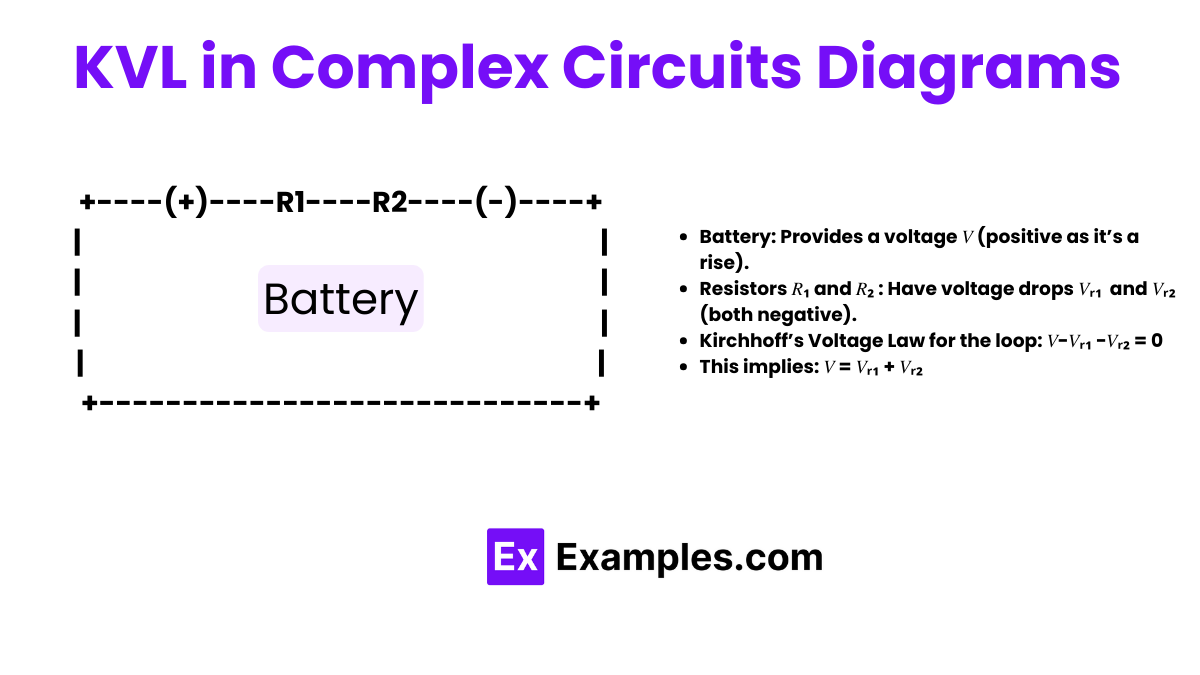
Circuit Diagram Example
To illustrate KVL, consider a simple circuit with a battery and two resistors in a single loop:
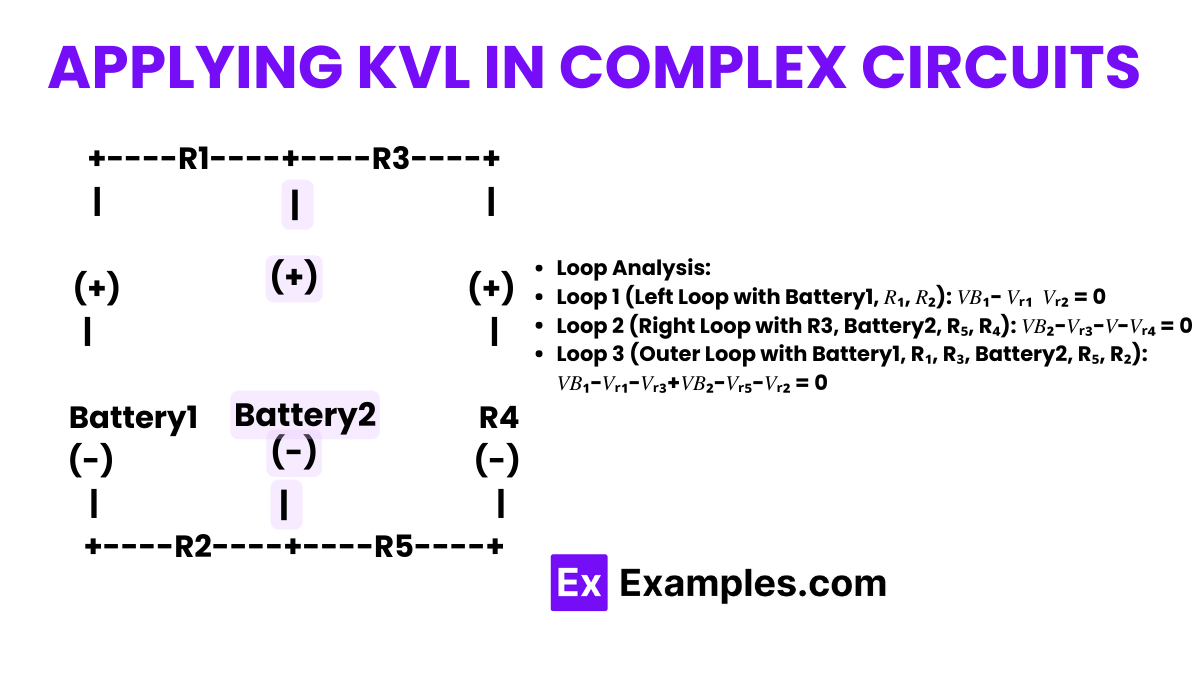
Applying KVL in Complex Circuits
For more complex circuits involving multiple loops, KVL can be applied to each loop separately. Here is a more complex example involving multiple loops and shared components:
FAQs
Who Discovered Kirchhoff’s Laws?
Kirchhoff’s Laws were discovered by Gustav Kirchhoff, a German physicist, in 1845. He formulated these laws to describe the conservation of current and energy in electrical circuits.
What Are Kirchhoff’s Laws
Kirchhoff’s Current Law (KCL) and Kirchhoff’s Voltage Law (KVL)
Does KCL apply to AC circuits?
Yes, KCL applies to both AC and DC circuits. In AC circuits, currents are typically represented as phasors, but the principle that the algebraic sum of currents at a node is zero still holds.
How do you apply KVL in a circuit?
To apply KVL, identify loops in the circuit and sum the voltage gains and drops around each loop. Ensure that the sum equals zero, accounting for voltage rises (sources) and falls (loads).