
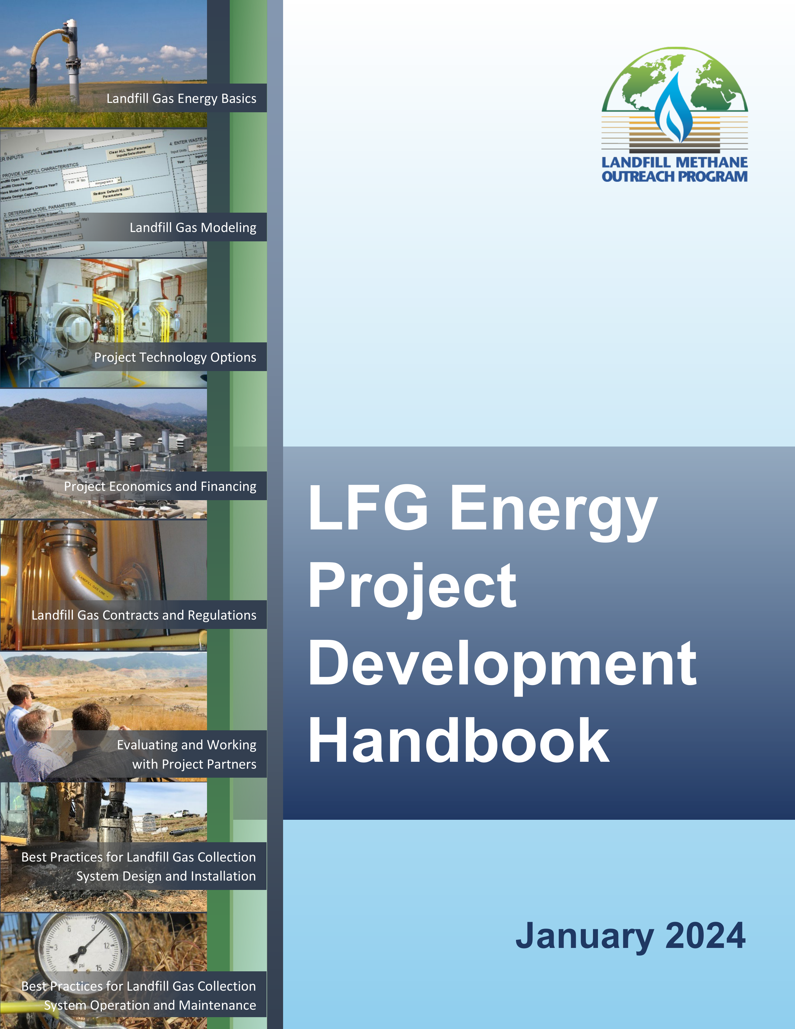
Landfill Gas Energy Basics
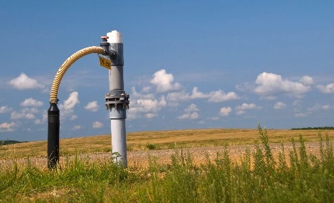
Landfill Gas Modeling
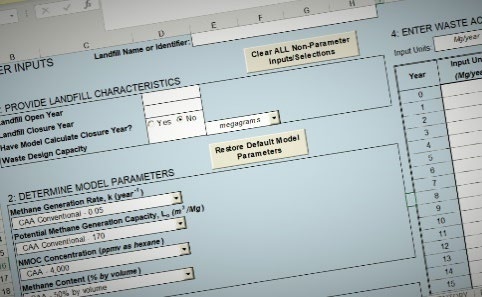
Project Technology Options
Project Economics and Financing
Landfill Gas Contracts and Regulations
Best Practices for Landfill Gas Collection
System Design and Installation
Best Practices for Landfill Gas Collection
System Operation and Maintenance
Evaluating and Working
with Project Partners
January 2024
LFG Energy
Project
Development
Handbook

LFG Energy Project Development Handbook
Contents
i
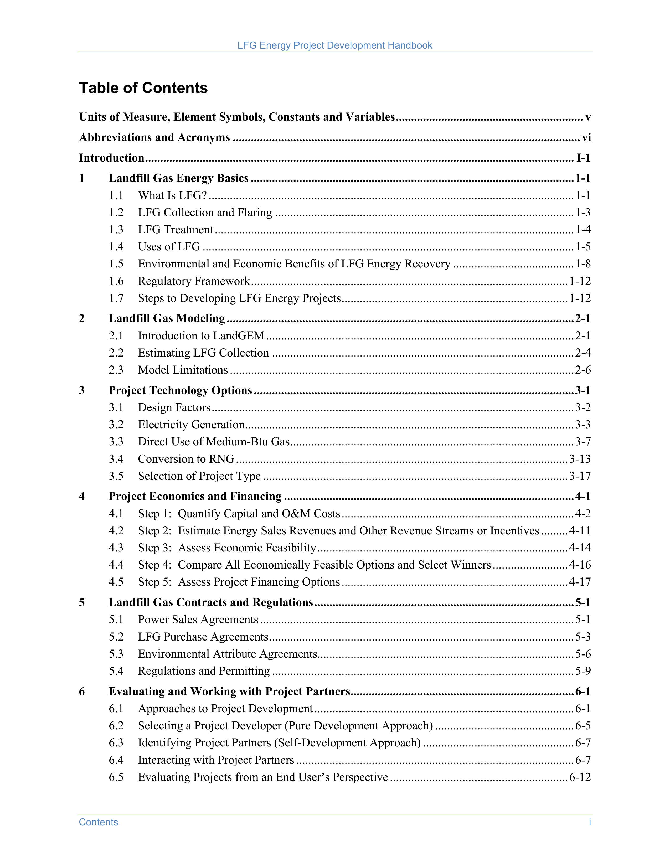
Table of Contents
Units of Measure, Element Symbols, Constants and Variables .............................................................. v
Abbreviations and Acronyms ................................................................................................................... vi
Introduction .............................................................................................................................................. I-1
1
Landfill Gas Energy Basics ........................................................................................................... 1-1
1.1
What Is LFG? ......................................................................................................................... 1-1
1.2
LFG Collection and Flaring ................................................................................................... 1-3
1.3
LFG Treatment ....................................................................................................................... 1-4
1.4
Uses of LFG ........................................................................................................................... 1-5
1.5
Environmental and Economic Benefits of LFG Energy Recovery ........................................ 1-8
1.6
Regulatory Framework ......................................................................................................... 1-12
1.7
Steps to Developing LFG Energy Projects ........................................................................... 1-12
2
Landfill Gas Modeling ................................................................................................................... 2-1
2.1
Introduction to LandGEM ...................................................................................................... 2-1
2.2
Estimating LFG Collection .................................................................................................... 2-4
2.3
Model Limitations .................................................................................................................. 2-6
3
Project Technology Options .......................................................................................................... 3-1
3.1
Design Factors ........................................................................................................................ 3-2
3.2
Electricity Generation ............................................................................................................. 3-3
3.3
Direct Use of Medium-Btu Gas .............................................................................................. 3-7
3.4
Conversion to RNG .............................................................................................................. 3-13
3.5
Selection of Project Type ..................................................................................................... 3-17
4
Project Economics and Financing ................................................................................................ 4-1
4.1
Step 1: Quantify Capital and O&M Costs ............................................................................. 4-2
4.2
Step 2: Estimate Energy Sales Revenues and Other Revenue Streams or Incentives ......... 4-11
4.3
Step 3: Assess Economic Feasibility ................................................................................... 4-14
4.4
Step 4: Compare All Economically Feasible Options and Select Winners ......................... 4-16
4.5
Step 5: Assess Project Financing Options ........................................................................... 4-17
5
Landfill Gas Contracts and Regulations ...................................................................................... 5-1
5.1
Power Sales Agreements ........................................................................................................ 5-1
5.2
LFG Purchase Agreements ..................................................................................................... 5-3
5.3
Environmental Attribute Agreements..................................................................................... 5-6
5.4
Regulations and Permitting .................................................................................................... 5-9
6
Evaluating and Working with Project Partners .......................................................................... 6-1
6.1
Approaches to Project Development ...................................................................................... 6-1
6.2
Selecting a Project Developer (Pure Development Approach) .............................................. 6-5
6.3
Identifying Project Partners (Self-Development Approach) .................................................. 6-7
6.4
Interacting with Project Partners ............................................................................................ 6-7
6.5
Evaluating Projects from an End User’s Perspective ........................................................... 6-12
LFG Energy Project Development Handbook
ii
Contents
7
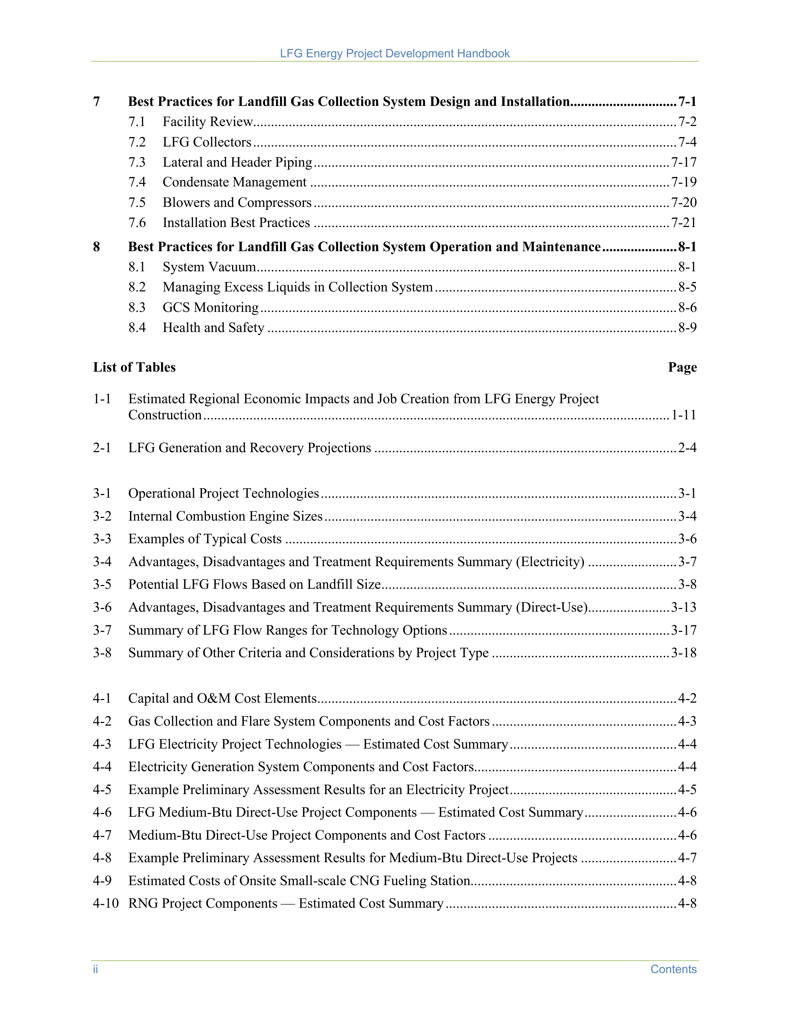
Best Practices for Landfill Gas Collection System Design and Installation.............................. 7-1
7.1
Facility Review....................................................................................................................... 7-2
7.2
LFG Collectors ....................................................................................................................... 7-4
7.3
Lateral and Header Piping .................................................................................................... 7-17
7.4
Condensate Management ..................................................................................................... 7-19
7.5
Blowers and Compressors .................................................................................................... 7-20
7.6
Installation Best Practices .................................................................................................... 7-21
8
Best Practices for Landfill Gas Collection System Operation and Maintenance ..................... 8-1
8.1
System Vacuum ...................................................................................................................... 8-1
8.2
Managing Excess Liquids in Collection System .................................................................... 8-5
8.3
GCS Monitoring ..................................................................................................................... 8-6
8.4
Health and Safety ................................................................................................................... 8-9
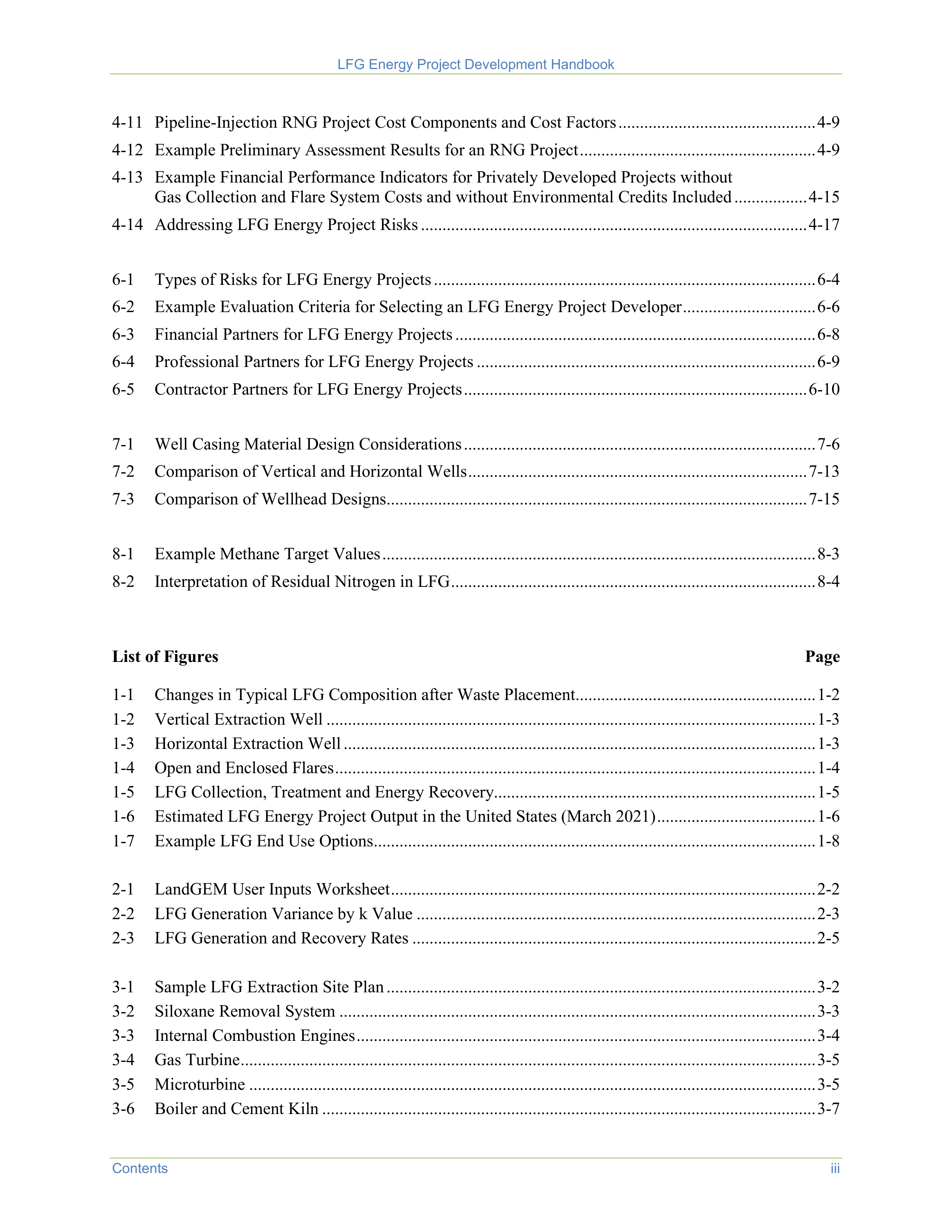
List of Tables
Page
1-1
Estimated Regional Economic Impacts and Job Creation from LFG Energy Project
Construction ................................................................................................................................... 1-11
2-1
LFG Generation and Recovery Projections ..................................................................................... 2-4
3-1
Operational Project Technologies .................................................................................................... 3-1
3-2
Internal Combustion Engine Sizes ................................................................................................... 3-4
3-3
Examples of Typical Costs .............................................................................................................. 3-6
3-4
Advantages, Disadvantages and Treatment Requirements Summary (Electricity) ......................... 3-7
3-5
Potential LFG Flows Based on Landfill Size ................................................................................... 3-8
3-6
Advantages, Disadvantages and Treatment Requirements Summary (Direct-Use) ....................... 3-13
3-7
Summary of LFG Flow Ranges for Technology Options .............................................................. 3-17
3-8
Summary of Other Criteria and Considerations by Project Type .................................................. 3-18
4-1
Capital and O&M Cost Elements ..................................................................................................... 4-2
4-2
Gas Collection and Flare System Components and Cost Factors .................................................... 4-3
4-3
LFG Electricity Project Technologies — Estimated Cost Summary ............................................... 4-4
4-4
Electricity Generation System Components and Cost Factors......................................................... 4-4
4-5
Example Preliminary Assessment Results for an Electricity Project ............................................... 4-5
4-6
LFG Medium-Btu Direct-Use Project Components — Estimated Cost Summary .......................... 4-6
4-7
Medium-Btu Direct-Use Project Components and Cost Factors ..................................................... 4-6
4-8
Example Preliminary Assessment Results for Medium-Btu Direct-Use Projects ........................... 4-7
4-9
Estimated Costs of Onsite Small-scale CNG Fueling Station.......................................................... 4-8
4-10 RNG Project Components — Estimated Cost Summary ................................................................. 4-8
LFG Energy Project Development Handbook
Contents
iii
4-11 Pipeline-Injection RNG Project Cost Components and Cost Factors .............................................. 4-9
4-12 Example Preliminary Assessment Results for an RNG Project ....................................................... 4-9
4-13 Example Financial Performance Indicators for Privately Developed Projects without
Gas Collection and Flare System Costs and without Environmental Credits Included ................. 4-15
4-14 Addressing LFG Energy Project Risks .......................................................................................... 4-17
6-1
Types of Risks for LFG Energy Projects ......................................................................................... 6-4
6-2
Example Evaluation Criteria for Selecting an LFG Energy Project Developer ............................... 6-6
6-3
Financial Partners for LFG Energy Projects .................................................................................... 6-8
6-4
Professional Partners for LFG Energy Projects ............................................................................... 6-9
6-5
Contractor Partners for LFG Energy Projects ................................................................................ 6-10
7-1
Well Casing Material Design Considerations .................................................................................. 7-6
7-2
Comparison of Vertical and Horizontal Wells ............................................................................... 7-13
7-3
Comparison of Wellhead Designs .................................................................................................. 7-15
8-1
Example Methane Target Values ..................................................................................................... 8-3
8-2
Interpretation of Residual Nitrogen in LFG ..................................................................................... 8-4
List of Figures
Page
1-1
Changes in Typical LFG Composition after Waste Placement ........................................................ 1-2
1-2
Vertical Extraction Well .................................................................................................................. 1-3
1-3
Horizontal Extraction Well .............................................................................................................. 1-3
1-4
Open and Enclosed Flares ................................................................................................................ 1-4
1-5
LFG Collection, Treatment and Energy Recovery........................................................................... 1-5
1-6
Estimated LFG Energy Project Output in the United States (March 2021) ..................................... 1-6
1-7
Example LFG End Use Options ....................................................................................................... 1-8
2-1
LandGEM User Inputs Worksheet ................................................................................................... 2-2
2-2
LFG Generation Variance by k Value ............................................................................................. 2-3
2-3
LFG Generation and Recovery Rates .............................................................................................. 2-5
3-1
Sample LFG Extraction Site Plan .................................................................................................... 3-2
3-2
Siloxane Removal System ............................................................................................................... 3-3
3-3
Internal Combustion Engines ........................................................................................................... 3-4
3-4
Gas Turbine ...................................................................................................................................... 3-5
3-5
Microturbine .................................................................................................................................... 3-5
3-6
Boiler and Cement Kiln ................................................................................................................... 3-7
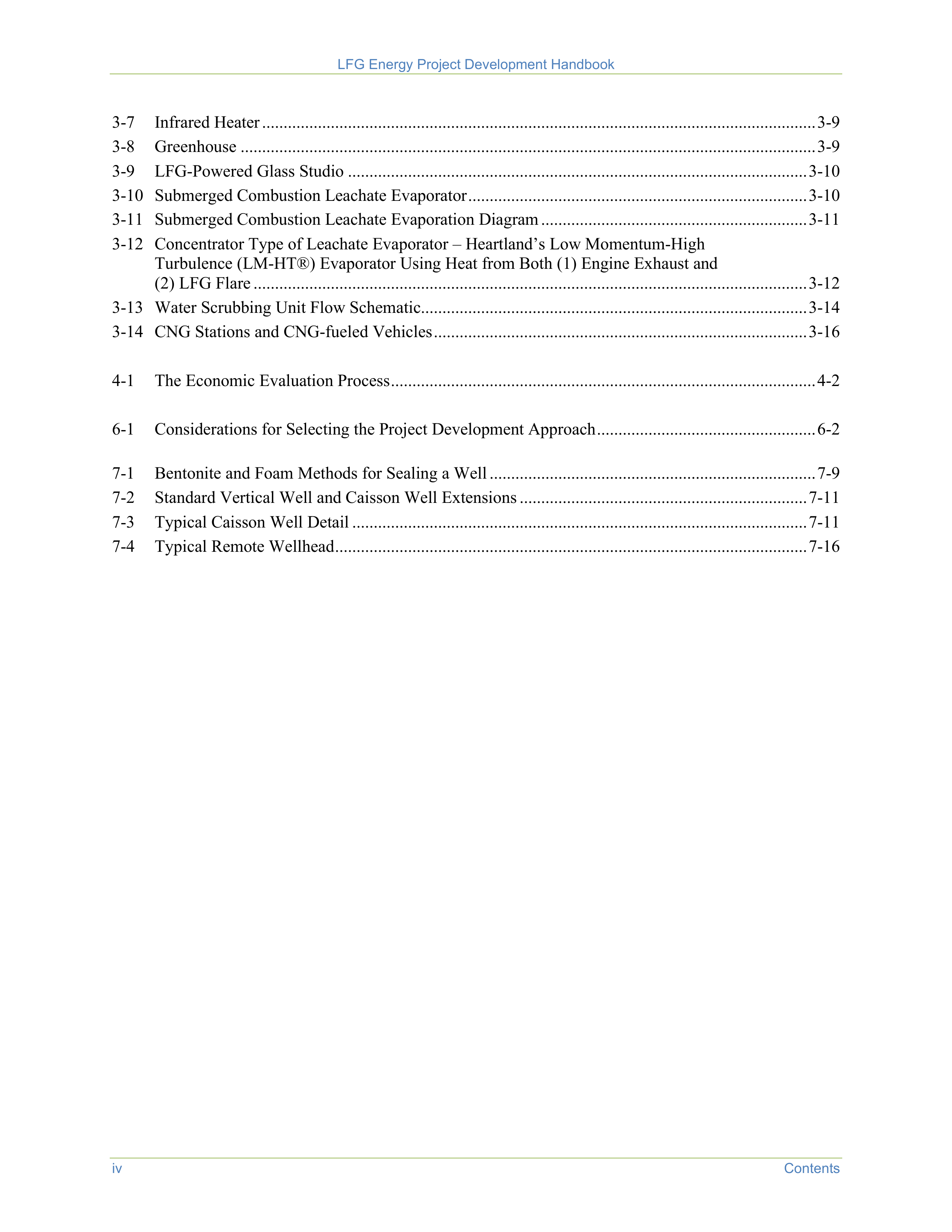
LFG Energy Project Development Handbook
iv
Contents
3-7
Infrared Heater ................................................................................................................................. 3-9
3-8
Greenhouse ...................................................................................................................................... 3-9
3-9
LFG-Powered Glass Studio ........................................................................................................... 3-10
3-10 Submerged Combustion Leachate Evaporator ............................................................................... 3-10
3-11 Submerged Combustion Leachate Evaporation Diagram .............................................................. 3-11
3-12 Concentrator Type of Leachate Evaporator – Heartland’s Low Momentum-High
Turbulence (LM-HT®) Evaporator Using Heat from Both (1) Engine Exhaust and
(2) LFG Flare ................................................................................................................................. 3-12
3-13 Water Scrubbing Unit Flow Schematic.......................................................................................... 3-14
3-14 CNG Stations and CNG-fueled Vehicles ....................................................................................... 3-16
4-1
The Economic Evaluation Process ................................................................................................... 4-2
6-1
Considerations for Selecting the Project Development Approach ................................................... 6-2
7-1
Bentonite and Foam Methods for Sealing a Well ............................................................................ 7-9
7-2
Standard Vertical Well and Caisson Well Extensions ................................................................... 7-11
7-3
Typical Caisson Well Detail .......................................................................................................... 7-11
7-4
Typical Remote Wellhead .............................................................................................................. 7-16
LFG Energy Project Development Handbook
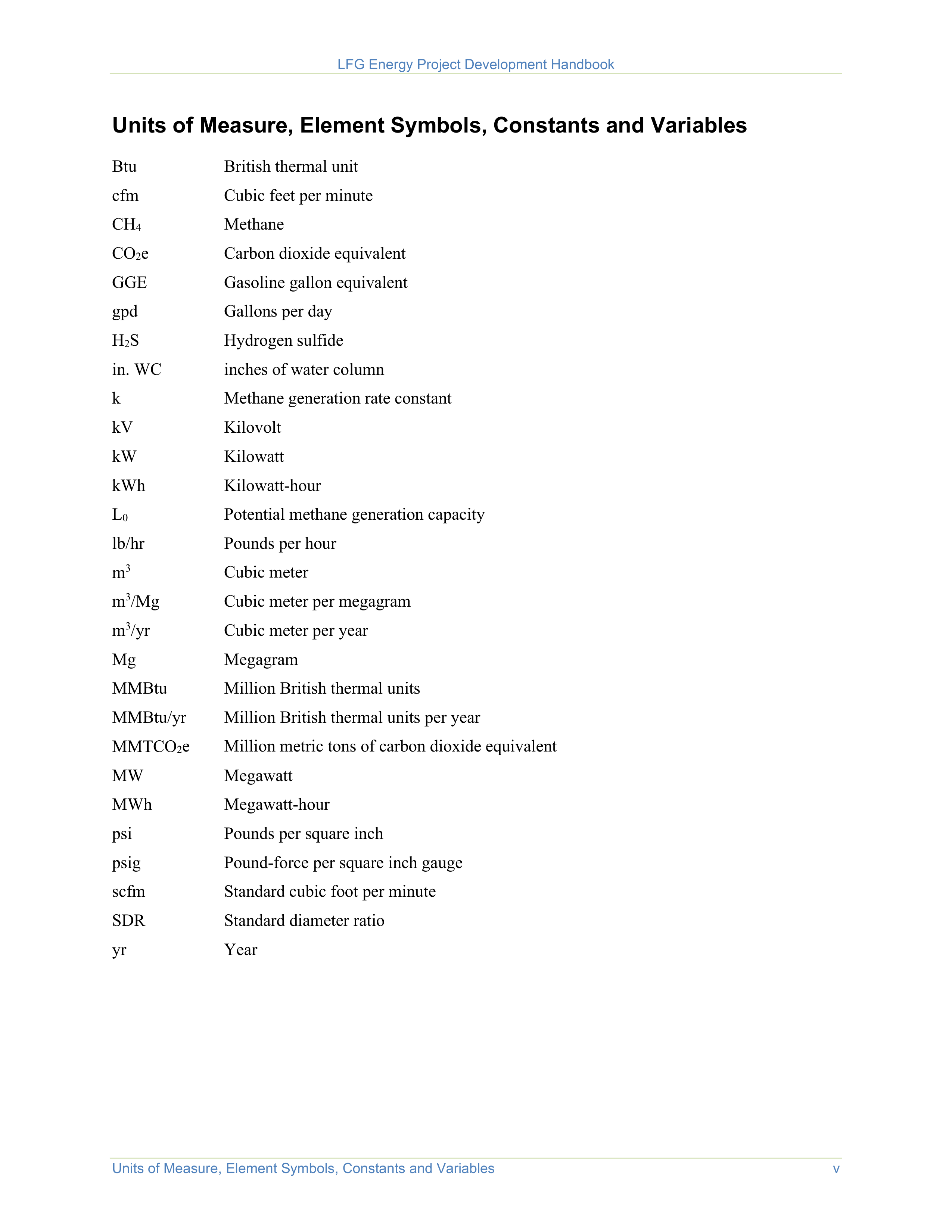
Units of Measure, Element Symbols, Constants and Variables
v
Units of Measure, Element Symbols, Constants and Variables
Btu
British thermal unit
cfm
Cubic feet per minute
CH
4
Methane
CO
2
e
Carbon dioxide equivalent
GGE
Gasoline gallon equivalent
gpd
Gallons per day
H
2
S
Hydrogen sulfide
in. WC
inches of water column
k
Methane generation rate constant
kV
Kilovolt
kW
Kilowatt
kWh
Kilowatt-hour
L
0
Potential methane generation capacity
lb/hr
Pounds per hour
m
3
Cubic meter
m
3
/Mg
Cubic meter per megagram
m
3
/yr
Cubic meter per year
Mg
Megagram
MMBtu
Million British thermal units
MMBtu/yr
Million British thermal units per year
MMTCO
2
e
Million metric tons of carbon dioxide equivalent
MW
Megawatt
MWh
Megawatt-hour
psi
Pounds per square inch
psig
Pound-force per square inch gauge
scfm
Standard cubic foot per minute
SDR
Standard diameter ratio
yr
Year
LFG Energy Project Development Handbook
vi
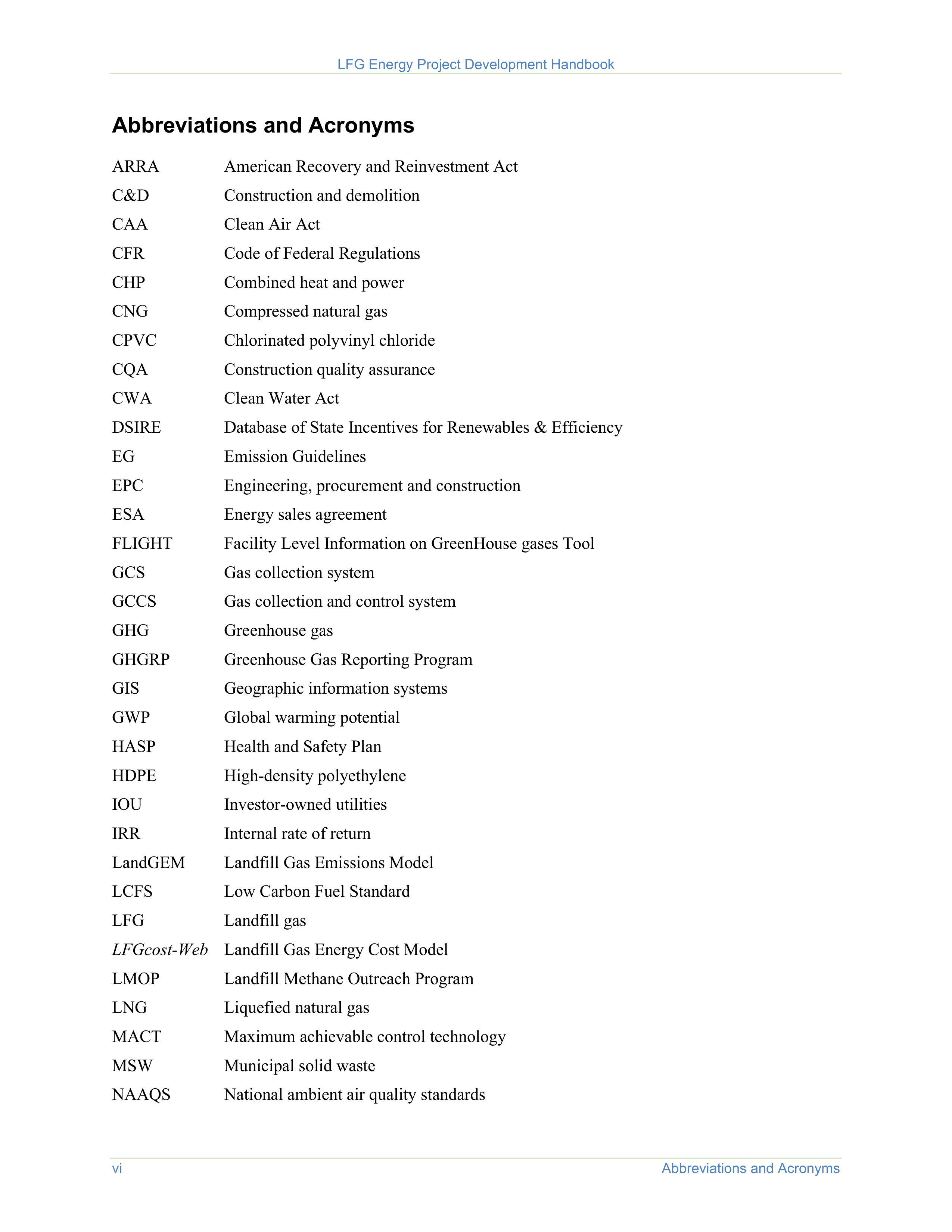
Abbreviations and Acronyms
Abbreviations and Acronyms
ARRA
American Recovery and Reinvestment Act
C&D
Construction and demolition
CAA
Clean Air Act
CFR
Code of Federal Regulations
CHP
Combined heat and power
CNG
Compressed natural gas
CPVC
Chlorinated polyvinyl chloride
CQA
Construction quality assurance
CWA
Clean Water Act
DSIRE
Database of State Incentives for Renewables & Efficiency
EG
Emission Guidelines
EPC
Engineering, procurement and construction
ESA
Energy sales agreement
FLIGHT
Facility Level Information on GreenHouse gases Tool
GCS
Gas collection system
GCCS
Gas collection and control system
GHG
Greenhouse gas
GHGRP
Greenhouse Gas Reporting Program
GIS
Geographic information systems
GWP
Global warming potential
HASP
Health and Safety Plan
HDPE
High-density polyethylene
IOU
Investor-owned utilities
IRR
Internal rate of return
LandGEM
Landfill Gas Emissions Model
LCFS
Low Carbon Fuel Standard
LFG
Landfill gas
LFGcost-Web
Landfill Gas Energy Cost Model
LMOP
Landfill Methane Outreach Program
LNG
Liquefied natural gas
MACT
Maximum achievable control technology
MSW
Municipal solid waste
NAAQS
National ambient air quality standards
LFG Energy Project Development Handbook
Abbreviations and Acronyms
vii
NAESB
North American Energy Standards Board
NESHAP
National Emission Standards for Hazardous Air Pollutants
NFPA
National Fire Protection Association
NMOC
Non-methane organic compound
NPDES
National Pollutant Discharge Elimination System
NPV
Net present value
NSPS
New Source Performance Standards
NSR
New Source Review
NYMEX
New York Mercantile Exchange
O&M
Operation and maintenance
OSHA
Occupational Safety and Health Administration
OTC
Over-the-counter
PFAS
Per- and polyfluoroalkyl substances
PPA
Power purchase agreement
PPE
Personal protective equipment
PSA
Power sales agreement
PSD
Prevention of Significant Deterioration
PVC
Polyvinyl chloride
RCRA
Resource Conservation and Recovery Act of 1976, as amended
REC
Renewable energy certificate
RFP
Request for proposal
RFS
Renewable Fuel Standard
RGGI
Regional Greenhouse Gas Initiative
RIN
Renewable Identification Number
RNG
Renewable natural gas
RPS
Renewable Portfolio Standard
RTC
Renewable thermal certificate
RTO
Regional transmission operator
RVO
Renewable volume obligation
SCADA
Supervisory control and data acquisition
SIP
State Implementation Plan
SOQ
Statement of Qualifications
SWANA
Solid Waste Association of North America
VFD
Variable frequency drive
WRRF
Water resource recovery facility



Introduction
I-1
Introduction
The
LFG Energy Project Development Handbook
provides an overview of landfill gas (LFG) energy
project development guidance and presents the technological, economic and regulatory considerations
that affect the feasibility and success of LFG energy projects. Landfill owners, energy service providers,
end users, representatives of state agencies and local government, community members and other
interested stakeholders will benefit from information provided in this handbook as they work together to
develop successful LFG energy projects.
This handbook presents national
statistics that reflect LMOP’s Landfill
and LFG Energy Project Database
as of March 2021. Project cost
estimates presented in this
handbook were calculated using
Version 3.5 of the Landfill Gas
Energy Cost Model (
LFGcost-Web
).
The handbook is organized into eight chapters:
Chapter 1 – Landfill Gas Energy Basics
Chapter 2 – Landfill Gas Modeling
Chapter 3 – Project Technology Options
Chapter 4 – Project Economics and Financing
Chapter 5 – Landfill Gas Contracts and Regulations
Chapter 6 – Evaluating and Working with Project Partners
Chapter 7 – Best Practices for Landfill Gas Collection System Design and Installation
Chapter 8 – Best Practices for Landfill Gas Collection System Operation and Maintenance
Using the Project Development Handbook
The handbook provides basic information that relates to all LFG energy projects and presents a more
detailed overview of project-specific considerations.
The handbook discusses the status of LFG energy in the United States and presents the basic steps of
developing an LFG energy project. Throughout the handbook, readers will find references to online
resources that contain more comprehensive details, examples and helpful tools. Readers are encouraged to
visit these resources to find information that may be relevant to individual projects and topics.
Disclaimer
The handbook is not an official guidance document. Instead, this document provides general information
regarding LFG energy projects. It does not address all information, factors, applicable regulations or
considerations that may be relevant or required. Any references to private entities, products or services
are strictly for informational purposes and do not constitute an endorsement of that entity, product or
service.


LFG Energy Project Development Handbook
I-2
Introduction
About LMOP
The Landfill Methane Outreach Program (LMOP) is a
voluntary program that works cooperatively with industry
stakeholders and waste officials to reduce or avoid
methane emissions from landfills. LMOP encourages the
recovery and beneficial use of biogas generated from
organic municipal solid waste (MSW). LMOP has
developed many publications and tools to assist those
wishing to develop LFG energy projects or to promote
LFG to various audiences. This handbook advances the
purpose and mission of LMOP by providing the tools and
necessary information to stakeholders for the development
of successful LFG energy projects.
LMOP’s website is one of the main
methods of providing LMOP Partners,
others in the industry and the public
with information about the latest LFG
energy-related advances,
opportunities, models and tools.
Visit
www.epa.gov/lmop/
for
complete details about LMOP.
Direct Assistance for Developing LFG Energy Projects.
LMOP offers direct assistance throughout the
development of a project, from providing basic information about LFG energy in the early stages of
project consideration, to preliminary analyses of project feasibility, to providing media support when the
project reaches the construction or commercial operation phase.
LMOP tools and resources
are available
on the LMOP website. Services LMOP offers include:
•
Assisting with preliminary technical and economic feasibility assessments for LFG energy project
options using tools such as
LFGcost-Web
.
•
Matching landfills and end users by helping a landfill owner/operator or project developer identify
potential end users or helping potential end users search for nearby landfills that are good candidates
for project development.
•
Making preliminary estimates of recoverable methane using LFG models such as the Landfill Gas
Emissions Model (LandGEM) and site-specific information on landfill waste acceptance.
•
Helping to locate project partners through networking opportunities and by distributing Requests for
Proposals (RFPs) through listserv messages.
•
Answering technical questions and providing information to help overcome technical barriers to LFG
energy projects. LMOP can also address questions about LFG energy and foster positive interactions
among landfill owners, developers, end users, regulatory agencies, community groups and other
stakeholders.
•
Providing positive publicity for LFG energy projects by developing outreach materials for project
ribbon cuttings.
Landfill and LFG Energy Project Database.
LMOP’s Landfill and LFG Energy Project Database is the
most comprehensive data repository in the country for information about LFG energy projects and
landfills with potential for energy recovery. It is updated with information from LMOP Partners and other
organizations in the industry. LMOP posts Excel files with landfill and project data on the LMOP website
for viewing and downloading. Users can view data for a specific project type of interest, for landfills that
are good candidates for energy project development or for all projects and landfills in a single state.
LMOP can also occasionally provide additional information to address specific questions about landfills
or projects. See
www.epa.gov/lmop/landfill-gas-energy-project-data-and-landfill-technical-data
.
Frequent Questions.
LMOP’s website provides answers to questions frequently asked about the program
itself, and LFG and LFG energy projects in general. See
www.epa.gov/lmop/frequent-questions-about-
landfill-gas
.




Landfill Gas Energy Basics
1-1
Harnessing the power of landfill gas (LFG) energy provides environmental and economic benefits to
landfills, energy users and the community. Working together, landfill owners, energy service providers,
businesses, state agencies, local governments, communities and other stakeholders can develop successful
LFG energy projects that:
•
Reduce emissions of greenhouse gases (GHGs) that
contribute to global climate change
•
Offset the use of non-renewable resources
•
Help improve local air quality
•
Provide revenue for landfills
•
Reduce energy costs for users of LFG energy
•
Create jobs and promote investment in local businesses
LMOP encourages and
facilitates development of
environmentally and
economically sound LFG
energy projects by partnering
with stakeholders and providing
a variety of information, tools
and services.
This chapter describes the source and characteristics of LFG and presents basic information about the
collection, treatment and use of LFG in energy recovery systems. This chapter also includes a discussion
of the status of LFG energy in the United States, a review of the benefits of LFG energy projects and a
summary of the current federal regulatory framework. Finally, it introduces general steps to LFG energy
project development.
MSW landfills are the third
largest human-caused source of
methane in the United States,
accounting for approximately
15.1 percent of U.S. methane
emissions in 2019.
2
1.1
What Is LFG?
LFG is a natural byproduct of the decomposition of organic
material in anaerobic (without oxygen) conditions. LFG
contains roughly 50 to 55 percent methane and 45 to 50 percent
carbon dioxide, with less than 1 percent non-methane organic
compounds (NMOCs) and trace amounts of inorganic compounds. Methane is a potent GHG 28 to 36
times more effective than carbon dioxide at trapping heat in the atmosphere over a 100-year period.
1
The
Landfill Methane Outreach Program (LMOP) uses a methane global warming potential (GWP) of 25 in
program calculations to be consistent with and comparable to key Agency emission quantification
programs such as the U.S. GHG Inventory.
2
When municipal solid waste (MSW) is first deposited in a
landfill, it undergoes an aerobic (with oxygen) decomposition stage when little methane is generated.
Then, typically within less than 1 year, anaerobic conditions are established and methane-producing
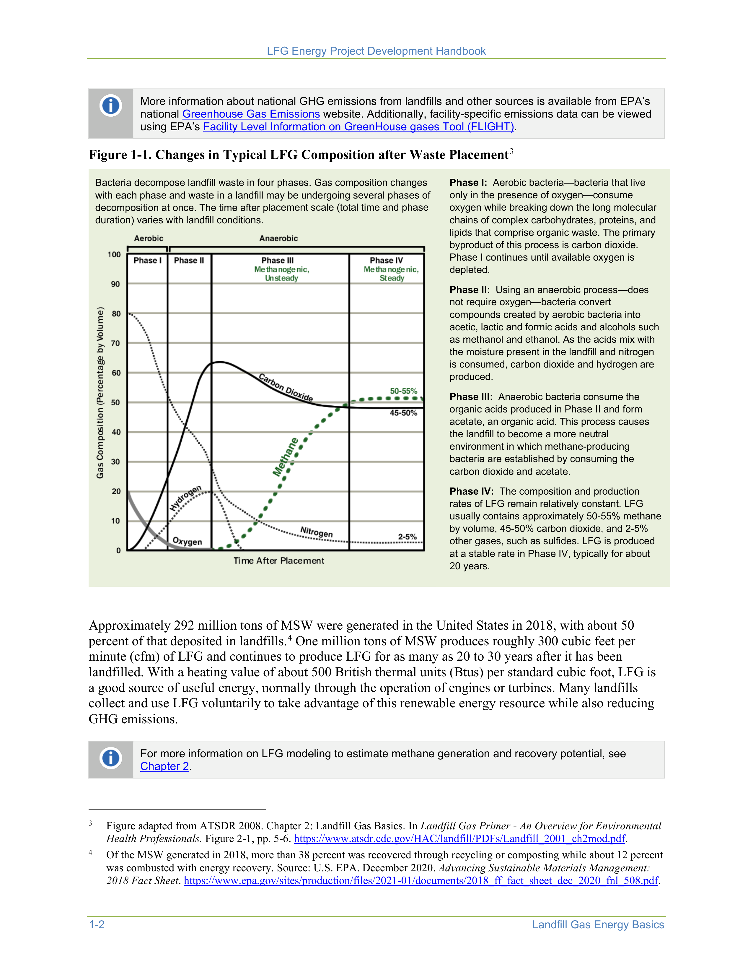
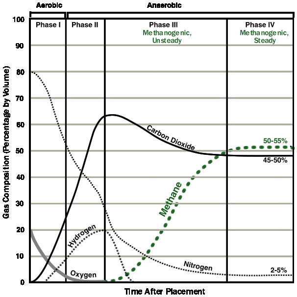
bacteria begin to decompose the waste and generate methane. Figure 1-1 illustrates the changes in typical
LFG composition over time.
1
In the latest Intergovernmental Panel on Climate Change (IPCC) assessment report (AR5), the methane GWP range is 28 to
36, compared to a GWP of 25 in AR4.
https://www.ipcc.ch/report/ar5/
.
2
Inventory of U.S. Greenhouse Gas Emissions and Sinks: 1990-2019
. U.S. Environmental Protection Agency. EPA 430-R-21-
005. April 2021.
https://www.epa.gov/ghgemissions/inventory-us-greenhouse-gas-emissions-and-sinks-1990-2019
.

LFG Energy Project Development Handbook
1-2
Landfill Gas Energy Basics
More information about national GHG emissions from landfills and other sources is available from EPA’s
national
Greenhouse Gas Emissions
website. Additionally, facility-specific emissions data can be viewed
using EPA’s
Facility Level Information on GreenHouse gases Tool (FLIGHT)
.
Figure 1-1. Changes in Typical LFG Composition after Waste Placement
3
3
Figure adapted from ATSDR 2008. Chapter 2: Landfill Gas Basics. In
Landfill Gas Primer - An Overview for Environmental
Health Professionals.
Figure 2-1, pp. 5-6.
https://www.atsdr.cdc.gov/HAC/landfill/PDFs/Landfill_2001_ch2mod.pdf
.
Bacteria decompose landfill waste in four phases. Gas composition changes
with each phase and waste in a landfill may be undergoing several phases of
decomposition at once. The time after placement scale (total time and phase
duration) varies with landfill conditions.
Phase I:
Aerobic bacteria—bacteria that live
only in the presence of oxygen—consume
oxygen while breaking down the long molecular
chains of complex carbohydrates, proteins, and
lipids that comprise organic waste. The primary
byproduct of this process is carbon dioxide.
Phase I continues until available oxygen is
depleted.
Phase II:
Using an anaerobic process—does
not require oxygen—bacteria convert
compounds created by aerobic bacteria into
acetic, lactic and formic acids and alcohols such
as methanol and ethanol. As the acids mix with
the moisture present in the landfill and nitrogen
is consumed, carbon dioxide and hydrogen are
produced.
Phase III:
Anaerobic bacteria consume the
organic acids produced in Phase II and form
acetate, an organic acid. This process causes
the landfill to become a more neutral
environment in which methane-producing
bacteria are established by consuming the
carbon dioxide and acetate.
Phase IV:
The composition and production
rates of LFG remain relatively constant. LFG
usually contains approximately 50-55% methane
by volume, 45-50% carbon dioxide, and 2-5%
other gases, such as sulfides. LFG is produced
at a stable rate in Phase IV, typically for about
20 years.
Approximately 292 million tons of MSW were generated in the United States in 2018, with about 50
percent of that deposited in landfills.
4
One million tons of MSW produces roughly 300 cubic feet per
minute (cfm) of LFG and continues to produce LFG for as many as 20 to 30 years after it has been
landfilled. With a heating value of about 500 British thermal units (Btus) per standard cubic foot, LFG is
a good source of useful energy, normally through the operation of engines or turbines. Many landfills
collect and use LFG voluntarily to take advantage of this renewable energy resource while also reducing
GHG emissions.
4
Of the MSW generated in 2018, more than 38 percent was recovered through recycling or composting while about 12 percent
was combusted with energy recovery. Source: U.S. EPA. December 2020.
Advancing Sustainable Materials Management:
2018 Fact Sheet
.
https://www.epa.gov/sites/production/files/2021-01/documents/2018_ff_fact_sheet_dec_2020_fnl_508.pdf
.
For more information on LFG modeling to estimate methane generation and recovery potential, see
Chapter 2
.
LFG Energy Project Development Handbook
Landfill Gas Energy Basics
1-3
1.2
LFG Collection and Flaring
LFG collection typically begins after a portion of the landfill (known as a “cell”) is closed to additional
waste placement. A gas collection system (GCS) can be configured with vertical wells, horizontal
trenches or both, and its design can vary based on factors such as location, operational goals and waste
filling practices. Most landfills with energy recovery systems include a flare for the combustion of excess
gas and for use during equipment downtimes. Each of these components is described below, followed by
a brief discussion of GCS and flare costs.
Gas Collection Wells and Horizontal Trenches.
The most common method of LFG collection involves
drilling vertical wells in the waste and connecting those wellheads to lateral piping that transports the gas
to a collection header using a blower or vacuum induction system. Another type of GCS uses horizontal
piping laid in trenches in the waste. Horizontal trench systems are useful in deeper landfills and in areas
of active filling. Some systems involve a combination of vertical wells and horizontal collectors. Well-
designed systems of either type are effective in collecting LFG. The design chosen depends on site-
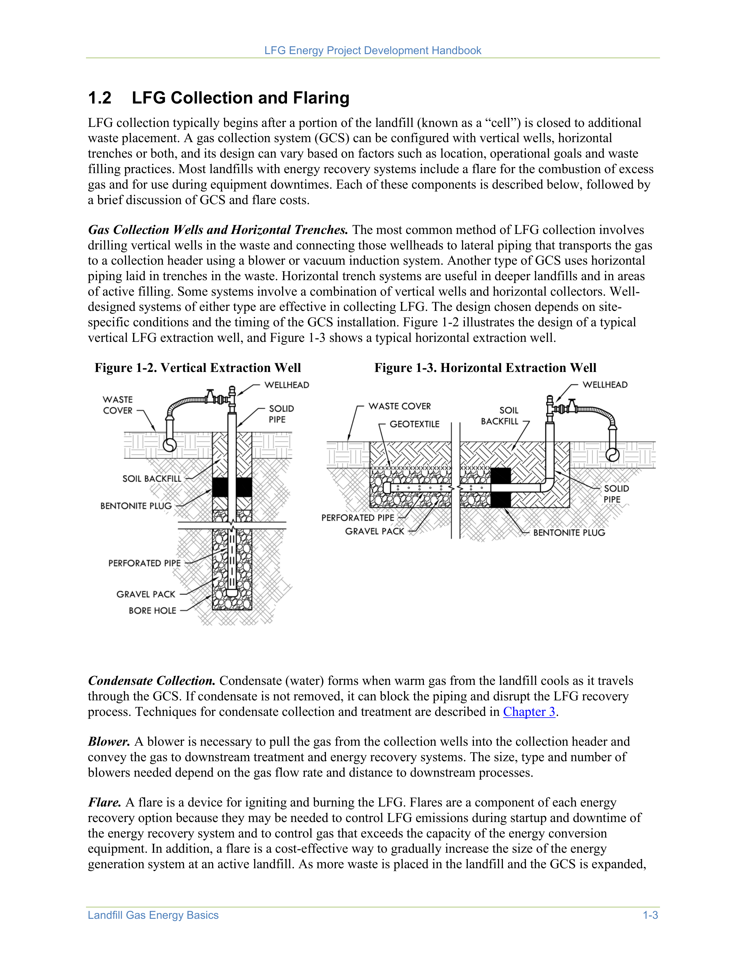
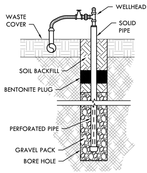
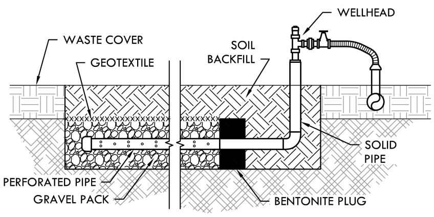
specific conditions and the timing of the GCS installation. Figure 1-2 illustrates the design of a typical
vertical LFG extraction well, and Figure 1-3 shows a typical horizontal extraction well.
Figure 1-2. Vertical Extraction Well
Figure 1-3. Horizontal Extraction Well
Condensate Collection.
Condensate (water) forms when warm gas from the landfill cools as it travels
through the GCS. If condensate is not removed, it can block the piping and disrupt the LFG recovery
process. Techniques for condensate collection and treatment are described in
Chapter 3
.
Blower.
A blower is necessary to pull the gas from the collection wells into the collection header and
convey the gas to downstream treatment and energy recovery systems. The size, type and number of
blowers needed depend on the gas flow rate and distance to downstream processes.
Flare.
A flare is a device for igniting and burning the LFG. Flares are a component of each energy
recovery option because they may be needed to control LFG emissions during startup and downtime of
the energy recovery system and to control gas that exceeds the capacity of the energy conversion
equipment. In addition, a flare is a cost-effective way to gradually increase the size of the energy
generation system at an active landfill. As more waste is placed in the landfill and the GCS is expanded,

LFG Energy Project Development Handbook
1-4
Landfill Gas Energy Basics
the flare is used to control excess gas between energy
conversion system upgrades (for example, before the
addition of another engine) to prevent methane from
being released into the atmosphere.
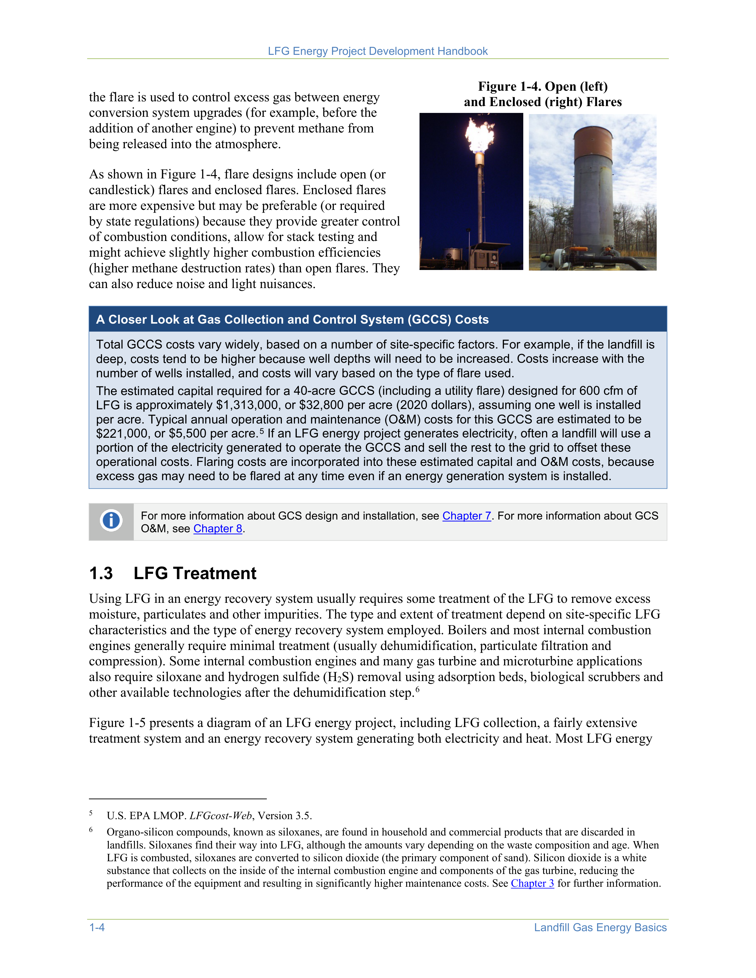
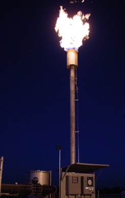
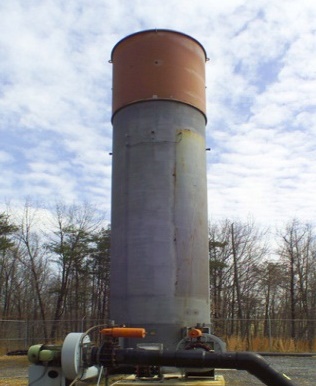
As shown in Figure 1-4, flare designs include open (or
candlestick) flares and enclosed flares. Enclosed flares
are more expensive but may be preferable (or required
by state regulations) because they provide greater control
of combustion conditions, allow for stack testing and
might achieve slightly higher combustion efficiencies
(higher methane destruction rates) than open flares. They
can also reduce noise and light nuisances.
Figure 1-4. Open (left)
and Enclosed (right) Flares
A Closer Look at Gas Collection and Control System (GCCS) Costs
Total GCCS costs vary widely, based on a number of site-specific factors. For example, if the landfill is
deep, costs tend to be higher because well depths will need to be increased. Costs increase with the
number of wells installed, and costs will vary based on the type of flare used.
The estimated capital required for a 40-acre GCCS (including a utility flare) designed for 600 cfm of
LFG is approximately $1,313,000, or $32,800 per acre (2020 dollars), assuming one well is installed
per acre. Typical annual operation and maintenance (O&M) costs for this GCCS are estimated to be
$221,000, or $5,500 per acre.
5
If an LFG energy project generates electricity, often a landfill will use a
portion of the electricity generated to operate the GCCS and sell the rest to the grid to offset these
operational costs. Flaring costs are incorporated into these estimated capital and O&M costs, because
excess gas may need to be flared at any time even if an energy generation system is installed.
5
U.S. EPA LMOP.
LFGcost-Web
, Version 3.5.
For more information about GCS design and installation, see
Chapter 7
. For more information about GCS
O&M, see
Chapter 8
.
1.3
LFG Treatment
Using LFG in an energy recovery system usually requires some treatment of the LFG to remove excess
moisture, particulates and other impurities. The type and extent of treatment depend on site-specific LFG
characteristics and the type of energy recovery system employed. Boilers and most internal combustion
engines generally require minimal treatment (usually dehumidification, particulate filtration and
compression). Some internal combustion engines and many gas turbine and microturbine applications
also require siloxane and hydrogen sulfide (H
2
S) removal using adsorption beds, biological scrubbers and
other available technologies after the dehumidification step.
6
6
Organo-silicon compounds, known as siloxanes, are found in household and commercial products that are discarded in
landfills. Siloxanes find their way into LFG, although the amounts vary depending on the waste composition and age. When
LFG is combusted, siloxanes are converted to silicon dioxide (the primary component of sand). Silicon dioxide is a white
substance that collects on the inside of the internal combustion engine and components of the gas turbine, reducing the
performance of the equipment and resulting in significantly higher maintenance costs. See
Chapter 3
for further information.
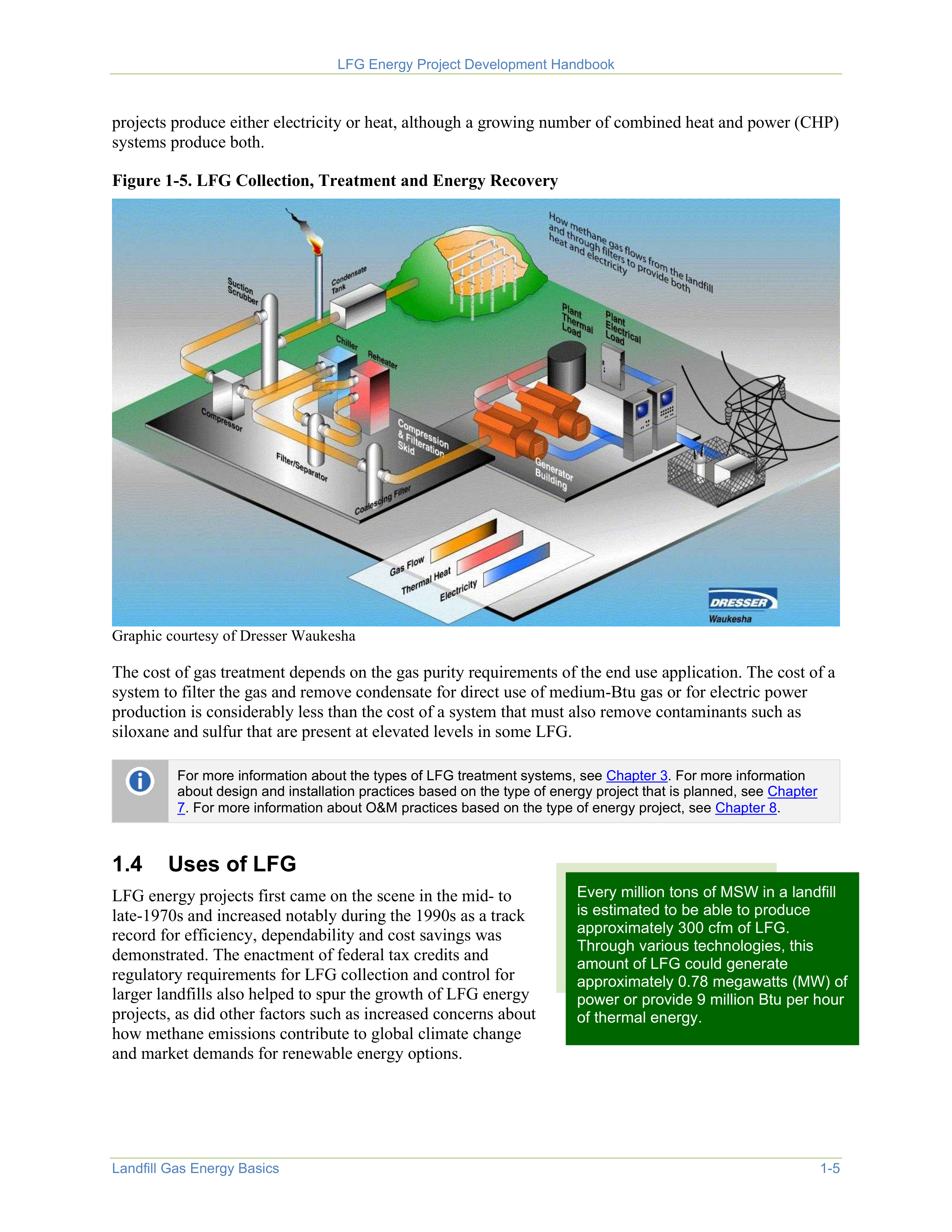
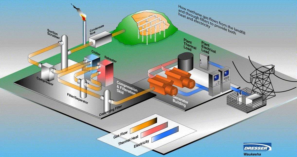
Figure 1-5 presents a diagram of an LFG energy project, including LFG collection, a fairly extensive
treatment system and an energy recovery system generating both electricity and heat. Most LFG energy



LFG Energy Project Development Handbook
Landfill Gas Energy Basics
1-5
projects produce either electricity or heat, although a growing number of combined heat and power (CHP)
systems produce both.
Figure 1-5. LFG Collection, Treatment and Energy Recovery
Graphic courtesy of Dresser Waukesha
The cost of gas treatment depends on the gas purity requirements of the end use application. The cost of a
system to filter the gas and remove condensate for direct use of medium-Btu gas or for electric power
production is considerably less than the cost of a system that must also remove contaminants such as
siloxane and sulfur that are present at elevated levels in some LFG.
For more information about the types of LFG treatment systems, see
Chapter 3
. For more information
about design and installation practices based on the type of energy project that is planned, see
Chapter
7
. For more information about O&M practices based on the type of energy project, see
Chapter 8
.
1.4
Uses of LFG
Every million tons of MSW in a landfill
is estimated to be able to produce
approximately 300 cfm of LFG.
Through various technologies, this
amount of LFG could generate
approximately 0.78 megawatts (MW) of
power or provide 9 million Btu per hour
of thermal energy.
LFG energy projects first came on the scene in the mid- to
late-1970s and increased notably during the 1990s as a track
record for efficiency, dependability and cost savings was
demonstrated. The enactment of federal tax credits and
regulatory requirements for LFG collection and control for
larger landfills also helped to spur the growth of LFG energy
projects, as did other factors such as increased concerns about
how methane emissions contribute to global climate change
and market demands for renewable energy options.

LFG Energy Project Development Handbook
1-6
Landfill Gas Energy Basics
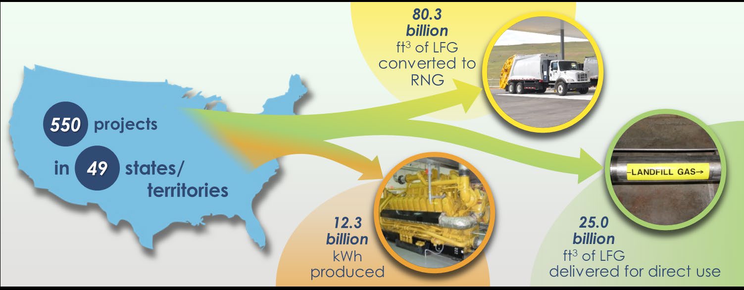
LMOP’s Landfill and LFG Energy Project Database, which tracks the development of U.S. LFG energy
projects and landfills with project development potential, indicates that, in March 2021, 550 LFG energy
projects were operating in 48 states and 1 U.S. territory. About 70 percent of these projects generate
electricity, while 17 percent are direct-use projects where the LFG is used for its thermal capacity and 13
percent are renewable natural gas (RNG) projects where the LFG is cleaned to a level comparable to
natural gas. Examples of direct-use projects include piping LFG to a nearby business or industry for use in
a boiler, furnace or kiln. The majority of RNG projects inject the cleaned gas into a natural gas pipeline.
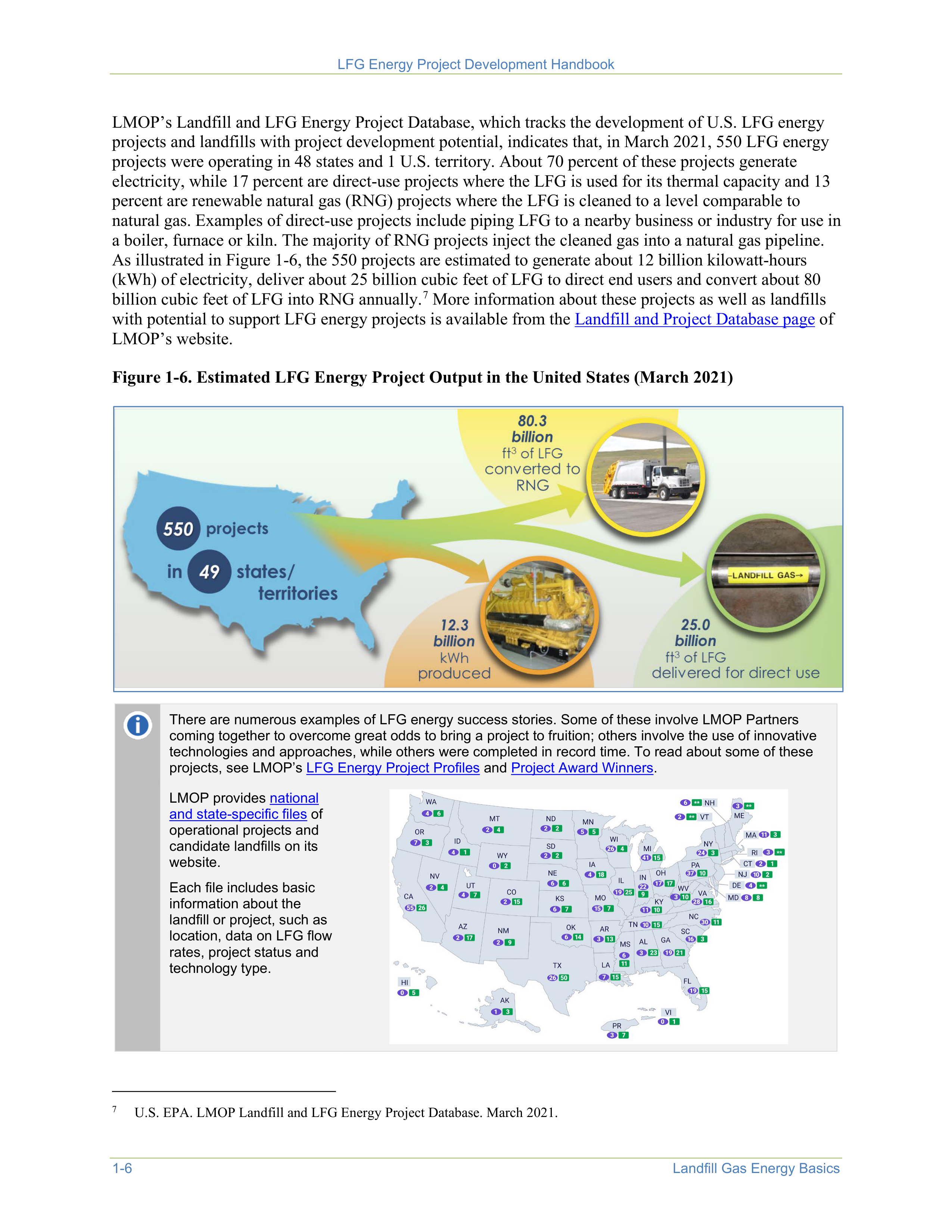
As illustrated in Figure 1-6, the 550 projects are estimated to generate about 12 billion kilowatt-hours
(kWh) of electricity, deliver about 25 billion cubic feet of LFG to direct end users and convert about 80
billion cubic feet of LFG into RNG annually.
7
More information about these projects as well as landfills
with potential to support LFG energy projects is available from the
Landfill and Project Database page
of
LMOP’s website.
7
U.S. EPA. LMOP Landfill and LFG Energy Project Database. March 2021.
Figure 1-6. Estimated LFG Energy Project Output in the United States (March 2021)
There are numerous examples of LFG energy success stories. Some of these involve LMOP Partners
coming together to overcome great odds to bring a project to fruition; others involve the use of innovative
technologies and approaches, while others were completed in record time. To read about some of these
projects, see LMOP’s
LFG Energy Project Profiles
and
Project Award Winners
.
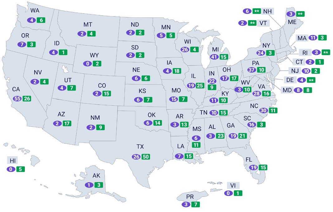
LMOP provides
national
and state-specific files
of
operational projects and
candidate landfills on its
website.
Each file includes basic
information about the
landfill or project, such as
location, data on LFG flow
rates, project status and
technology type.


LFG Energy Project Development Handbook
Landfill Gas Energy Basics
1-7
Electricity Generation
The three most commonly used technologies for LFG energy projects that generate electricity — internal
combustion engines, gas turbines and microturbines — can accommodate a wide range of project sizes.
Most (more than 85 percent) of the LFG energy projects that generated electricity in 2021 used internal
combustion engines, which are well-suited for 800-kilowatt (kW) to 3-MW projects. Multiple internal
combustion engines can be used together for projects larger than 3 MW. Gas turbines are more likely to
be used for large projects, usually 5 MW or larger. Microturbines, as their name suggests, are much
smaller than gas turbines, with a single unit having between 30 and 250 kW in capacity, and are generally
used for projects smaller than 1 MW. Small internal combustion engines are also available for projects in
this size range.
CHP applications, also known as cogeneration projects, provide greater overall energy efficiency. In
addition to producing electricity, these projects recover and beneficially use the heat from the unit
combusting the LFG. LFG energy CHP projects can use internal combustion engines, gas turbines or
microturbine technologies.
Other LFG electricity generation technologies include boiler/steam
turbines and combined cycle applications. In boiler/steam turbine
applications, LFG is combusted in a large boiler to generate steam
that powers a turbine to create electricity. Combined cycle
applications combine a gas turbine with a steam turbine, so that the
gas turbine combusts the LFG and the steam turbine uses the steam
generated from the gas turbine’s exhaust to create electricity.
Boiler/steam turbine and combined cycle applications tend to be
larger in scale than the majority of LFG electricity projects that use
internal combustion engines.
An LFG energy project may
use multiple units to
accommodate a landfill’s
specific gas flow over time.
For example, a project might
have three internal
combustion engines, two gas
turbines or an array of 10
microturbines, depending on
gas flow and energy needs.
Direct Use
When fossil fuel prices are high, direct use of LFG can offer a cost-effective alternative for fueling
combustion or heating equipment at facilities located within approximately 5 miles of a landfill. In some
situations, longer pipelines have been economically feasible based on the amount of LFG collected, the
fuel demand of the end user and the price of the fuel the LFG will replace. Some manufacturing plants
have chosen to locate near a landfill for the express purpose of using LFG as a renewable fuel that is cost-
effective as compared to natural gas.
Direct-use LFG applications are diverse. Project types include:
•
Boilers
, which
are the most common type of direct use and can often be easily converted to use LFG
alone or in combination with fossil fuels.
•
Direct thermal applications
,
which include kilns (cement, pottery or brick), sludge dryers, infrared
heaters, paint shop oven burners, tunnel furnaces, process heaters and blacksmithing forges. LFG has
also been used in a few greenhouse operations.
•
Leachate evaporation
,
in which a combustion device that uses LFG is used to evaporate leachate (the
liquid that percolates through a landfill). Leachate evaporation can reduce the cost of treating and
disposing of leachate.

LFG Energy Project Development Handbook
1-8
Landfill Gas Energy Basics
Renewable Natural Gas
The creation of RNG, or pipeline-quality gas, from LFG is not new but has grown in popularity over time.
In this process, LFG is cleaned and purified (carbon dioxide and impurities removed) until it is at the
quality that can be directly injected into a natural gas pipeline. In some RNG projects, the cleaned gas is
directly used as an alternative fuel (for example, compressed natural gas [CNG], liquefied natural gas
[LNG] or methanol).
For more information about electricity, direct-use and RNG technologies, see
Chapter 3.
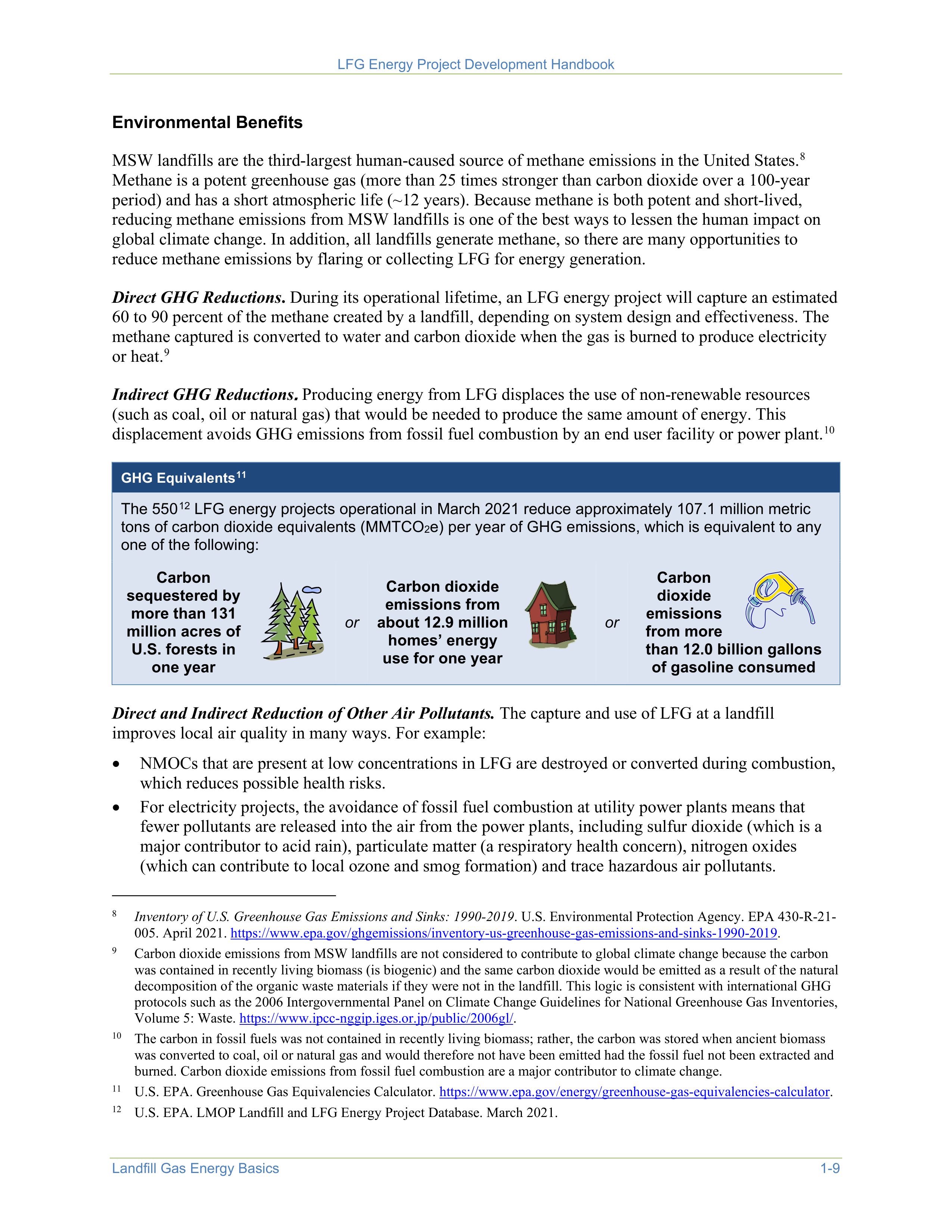
Figure 1-7 graphically depicts some of the potential end use options for LFG energy projects such as
generating electricity, providing medium-Btu gas for direct use in heating or other purposes or upgrading
the LFG to RNG for transportation fuel or other uses.
Figure 1-7. Example LFG End Use Options
1.5
Environmental and Economic Benefits of LFG Energy Recovery
Developing LFG energy projects is an effective way to reduce GHG emissions, improve local air quality
and control odors. This section highlights the numerous environmental and economic benefits that LFG
energy projects provide to the community, the landfill and the energy end user.

LFG Energy Project Development Handbook
Landfill Gas Energy Basics
1-9
Environmental Benefits
MSW landfills are the third-largest human-caused source of methane emissions in the United States.
8
Methane is a potent greenhouse gas (more than 25 times stronger than carbon dioxide over a 100-year
period) and has a short atmospheric life (~12 years). Because methane is both potent and short-lived,
reducing methane emissions from MSW landfills is one of the best ways to lessen the human impact on
global climate change. In addition, all landfills generate methane, so there are many opportunities to
reduce methane emissions by flaring or collecting LFG for energy generation.
8
Inventory of U.S. Greenhouse Gas Emissions and Sinks: 1990-2019
. U.S. Environmental Protection Agency. EPA 430-R-21-
005. April 2021.
https://www.epa.gov/ghgemissions/inventory-us-greenhouse-gas-emissions-and-sinks-1990-2019
.
Direct GHG Reductions
.
During its operational lifetime, an LFG energy project will capture an estimated
60 to 90 percent of the methane created by a landfill, depending on system design and effectiveness. The
methane captured is converted to water and carbon dioxide when the gas is burned to produce electricity
or heat.
9
9
Carbon dioxide emissions from MSW landfills are not considered to contribute to global climate change because the carbon
was contained in recently living biomass (is biogenic) and the same carbon dioxide would be emitted as a result of the natural
decomposition of the organic waste materials if they were not in the landfill. This logic is consistent with international GHG
protocols such as the 2006 Intergovernmental Panel on Climate Change Guidelines for National Greenhouse Gas Inventories,
Volume 5: Waste.
https://www.ipcc-nggip.iges.or.jp/public/2006gl/
.
Indirect GHG Reductions
.
Producing energy from LFG displaces the use of non-renewable resources
(such as coal, oil or natural gas) that would be needed to produce the same amount of energy. This
displacement avoids GHG emissions from fossil fuel combustion by an end user facility or power plant.
10
10
The carbon in fossil fuels was not contained in recently living biomass; rather, the carbon was stored when ancient biomass
was converted to coal, oil or natural gas and would therefore not have been emitted had the fossil fuel not been extracted and
burned. Carbon dioxide emissions from fossil fuel combustion are a major contributor to climate change.
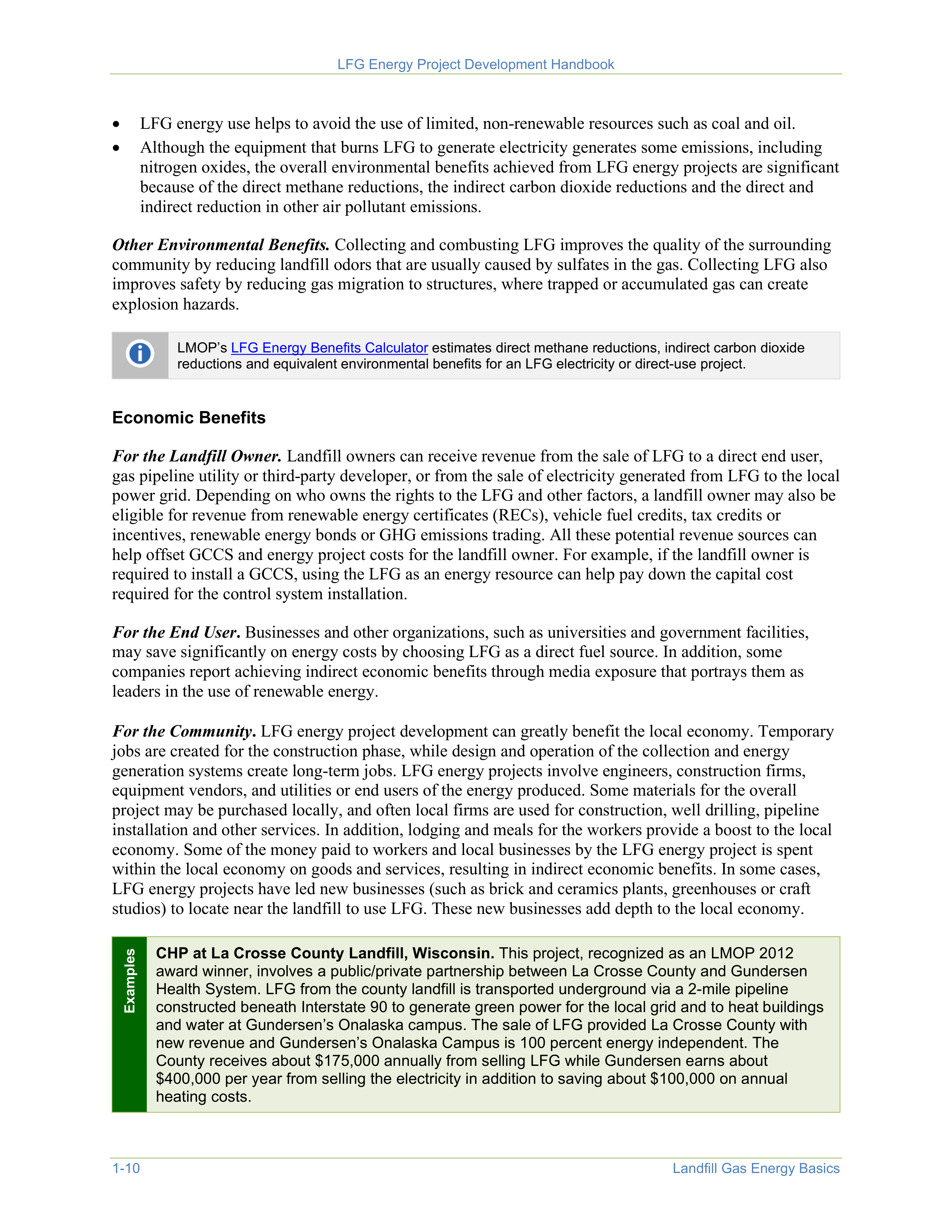
GHG Equivalents
11
The 550
12
LFG energy projects operational in March 2021 reduce approximately 107.1 million metric
tons of carbon dioxide equivalents (MMTCO
2
e) per year of GHG emissions, which is equivalent to any
one of the following:
Carbon
sequestered by
more than 131
million acres of
U.S. forests in
one year
or
Carbon dioxide
emissions from
about 12.9 million
homes’ energy
use for one year
or
Carbon
dioxide
emissions
from more
than 12.0 billion gallons
of gasoline consumed
11
U.S. EPA. Greenhouse Gas Equivalencies Calculator.
https://www.epa.gov/energy/greenhouse-gas-equivalencies-calculator
.
12
U.S. EPA. LMOP Landfill and LFG Energy Project Database. March 2021.
Direct and Indirect Reduction of Other Air Pollutants.
The capture and use of LFG at a landfill
improves local air quality in many ways. For example:
•
NMOCs that are present at low concentrations in LFG are destroyed or converted during combustion,
which reduces possible health risks.
•
For electricity projects, the avoidance of fossil fuel combustion at utility power plants means that
fewer pollutants are released into the air from the power plants, including sulfur dioxide (which is a
major contributor to acid rain), particulate matter (a respiratory health concern), nitrogen oxides
(which can contribute to local ozone and smog formation) and trace hazardous air pollutants.

LFG Energy Project Development Handbook
1-10
Landfill Gas Energy Basics
•
LFG energy use helps to avoid the use of limited, non-renewable resources such as coal and oil.
•
Although the equipment that burns LFG to generate electricity generates some emissions, including
nitrogen oxides, the overall environmental benefits achieved from LFG energy projects are significant
because of the direct methane reductions, the indirect carbon dioxide reductions and the direct and
indirect reduction in other air pollutant emissions.
Other Environmental Benefits.
Collecting and combusting LFG improves the quality of the surrounding
community by reducing landfill odors that are usually caused by sulfates in the gas. Collecting LFG also
improves safety by reducing gas migration to structures, where trapped or accumulated gas can create
explosion hazards.
LMOP’s
LFG Energy Benefits Calculator
estimates direct methane reductions, indirect carbon dioxide
reductions and equivalent environmental benefits for an LFG electricity or direct-use project.
Economic Benefits
For the Landfill Owner.
Landfill owners can receive revenue from the sale of LFG to a direct end user,
gas pipeline utility or third-party developer, or from the sale of electricity generated from LFG to the local
power grid. Depending on who owns the rights to the LFG and other factors, a landfill owner may also be
eligible for revenue from renewable energy certificates (RECs), vehicle fuel credits, tax credits or
incentives,
renewable energy bonds or GHG emissions trading. All these potential revenue sources can
help offset GCCS and energy project costs for the landfill owner. For example, if the landfill owner is
required to install a GCCS, using the LFG as an energy resource can help pay down the capital cost
required for the control system installation.
For the End User
.
Businesses and other organizations, such as universities and government facilities,
may save significantly on energy costs by choosing LFG as a direct fuel source. In addition, some
companies report achieving indirect economic benefits through media exposure that portrays them as
leaders in the use of renewable energy.
For the Community
.
LFG energy project development can greatly benefit the local economy. Temporary
jobs are created for the construction phase, while design and operation of the collection and energy
generation systems create long-term jobs. LFG energy projects involve engineers, construction firms,
equipment vendors, and utilities or end users of the energy produced. Some materials for the overall
project may be purchased locally, and often local firms are used for construction, well drilling, pipeline
installation and other services. In addition, lodging and meals for the workers provide a boost to the local
economy. Some of the money paid to workers and local businesses by the LFG energy project is spent
within the local economy on goods and services, resulting in indirect economic benefits. In some cases,
LFG energy projects have led new businesses (such as brick and ceramics plants, greenhouses or craft
studios) to locate near the landfill to use LFG. These new businesses add depth to the local economy.
Examples
CHP at La Crosse County Landfill, Wisconsin.
This project, recognized as an LMOP 2012
award winner, involves a public/private partnership between La Crosse County and Gundersen
Health System. LFG from the county landfill is transported underground via a 2-mile pipeline
constructed beneath Interstate 90 to generate green power for the local grid and to heat buildings
and water at Gundersen’s Onalaska campus. The sale of LFG provided La Crosse County with
new revenue and Gundersen’s Onalaska Campus is 100 percent energy independent. The
County receives about $175,000 annually from selling LFG while Gundersen earns about
$400,000 per year from selling the electricity in addition to saving about $100,000 on annual
heating costs.

LFG Energy Project Development Handbook
Landfill Gas Energy Basics
1-11
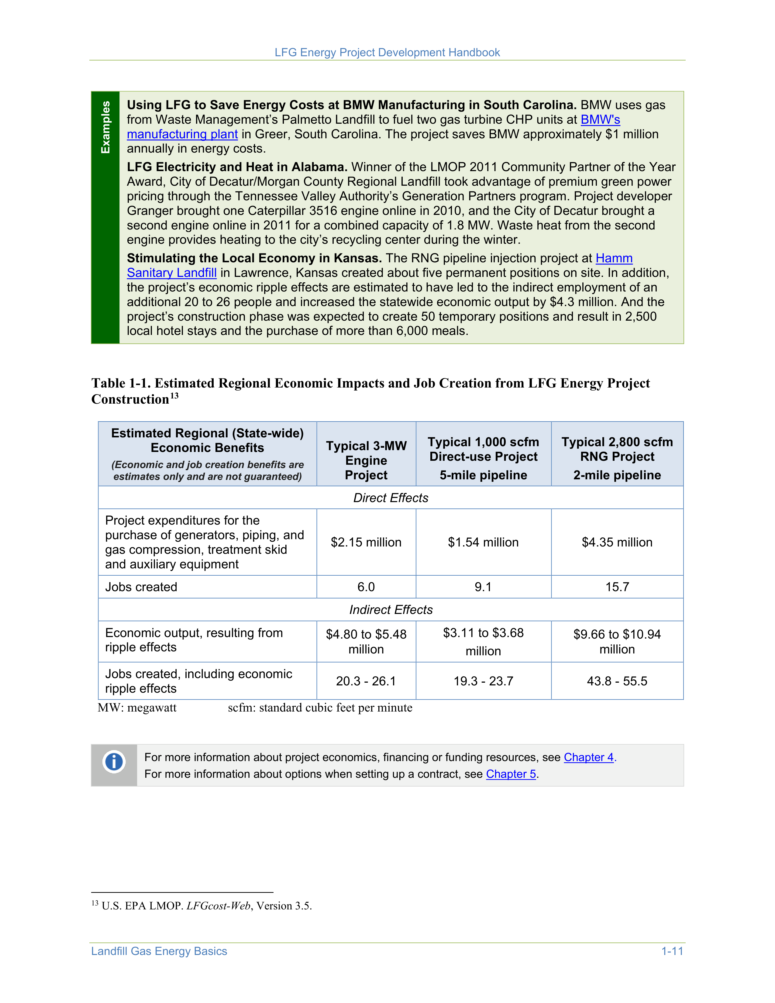
Examples
Using LFG to Save Energy Costs at BMW Manufacturing in South Carolina.
BMW uses gas
from Waste Management’s Palmetto Landfill to fuel two gas turbine CHP units at
BMW's
manufacturing plant
in Greer, South Carolina. The project saves BMW approximately $1 million
annually in energy costs.
LFG Electricity and Heat in Alabama.
Winner of the LMOP 2011 Community Partner of the Year
Award, City of Decatur/Morgan County Regional Landfill took advantage of premium green power
pricing through the Tennessee Valley Authority’s Generation Partners program. Project developer
Granger brought one Caterpillar 3516 engine online in 2010, and the City of Decatur brought a
second engine online in 2011 for a combined capacity of 1.8 MW. Waste heat from the second
engine provides heating to the city’s recycling center during the winter.
Stimulating the Local Economy in Kansas.
The RNG pipeline injection project at
Hamm
Sanitary Landfill
in Lawrence, Kansas created about five permanent positions on site. In addition,
the project’s economic ripple effects are estimated to have led to the indirect employment of an
additional 20 to 26 people and increased the statewide economic output by $4.3 million. And the
project’s construction phase was expected to create 50 temporary positions and result in 2,500
local hotel stays and the purchase of more than 6,000 meals.
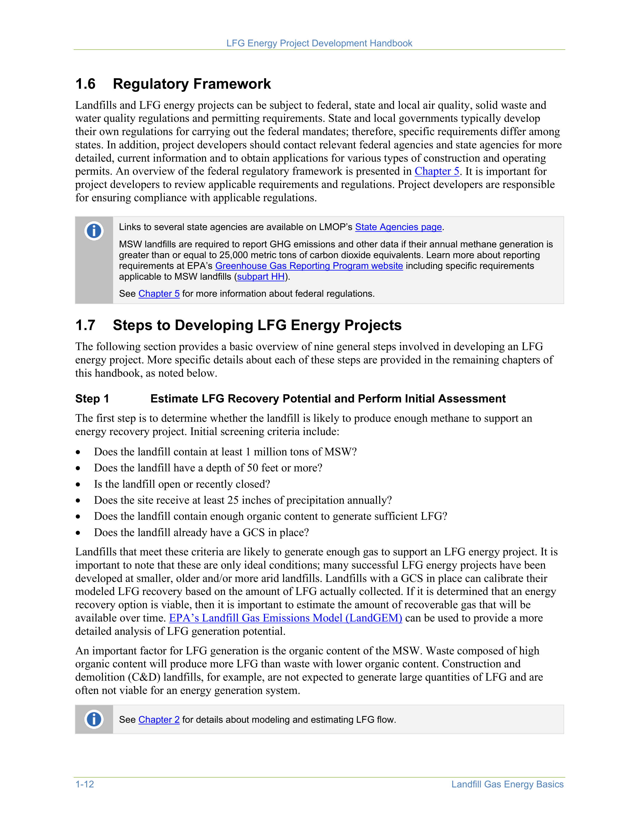
Table 1-1. Estimated Regional Economic Impacts and Job Creation from LFG Energy Project
Construction
13
13
U.S. EPA LMOP.
LFGcost-Web
, Version 3.5.
Estimated Regional (State-wide)
Economic Benefits
(Economic and job creation benefits are
estimates only and are not guaranteed)
Typical 3-MW
Engine
Project
Typical 1,000 scfm
Direct-use Project
5-mile pipeline
Typical 2,800 scfm
RNG Project
2-mile pipeline
Direct Effects
Project expenditures for the
purchase of generators, piping, and
gas compression, treatment skid
and auxiliary equipment
$2.15 million
$1.54 million
$4.35 million
Jobs created
6.0
9.1
15.7
Indirect Effects
Economic output, resulting from
ripple effects
$4.80 to $5.48
million
$3.11 to $3.68
million
$9.66 to $10.94
million
Jobs created, including economic
ripple effects
20.3 - 26.1
19.3 - 23.7
43.8 - 55.5
MW: megawatt
scfm: standard cubic feet per minute
For more information about project economics, financing or funding resources, see
Chapter 4.
For more information about options when setting up a contract, see
Chapter 5
.

LFG Energy Project Development Handbook
1-12
Landfill Gas Energy Basics
1.6
Regulatory Framework
Landfills and LFG energy projects can be subject to federal, state and local air quality, solid waste and
water quality regulations and permitting requirements. State and local governments typically develop
their own regulations for carrying out the federal mandates; therefore, specific requirements differ among
states. In addition, project developers should contact relevant federal agencies and state agencies for more
detailed, current information and to obtain applications for various types of construction and operating
permits. An overview of the federal regulatory framework is presented in
Chapter 5
. It is important for
project developers to review applicable requirements and regulations. Project developers are responsible
for ensuring compliance with applicable regulations.
Links to several state agencies are available on LMOP’s
State Agencies page
.
MSW landfills are required to report GHG emissions and other data if their annual methane generation is
greater than or equal to 25,000 metric tons of carbon dioxide equivalents. Learn more about reporting
requirements at EPA’s
Greenhouse Gas Reporting Program website
including specific requirements
applicable to MSW landfills (
subpart HH
).
See
Chapter 5
for more information about federal regulations.
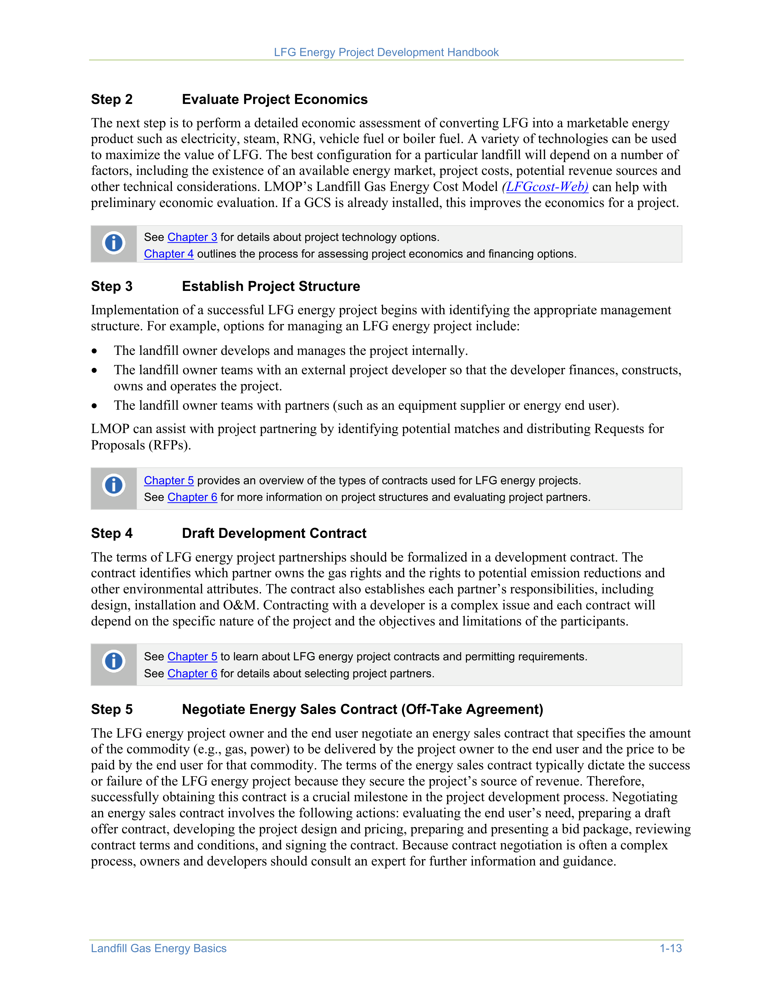
1.7
Steps to Developing LFG Energy Projects
The following section provides a basic overview of nine general steps involved in developing an LFG
energy project. More specific details about each of these steps are provided in the remaining chapters of
this handbook, as noted below.
Step 1
Estimate LFG Recovery Potential and Perform Initial Assessment
The first step is to determine whether the landfill is likely to produce enough methane to support an
energy recovery project. Initial screening criteria include:
•
Does the landfill contain at least 1 million tons of MSW?
•
Does the landfill have a depth of 50 feet or more?
•
Is the landfill open or recently closed?
•
Does the site receive at least 25 inches of precipitation annually?
•
Does the landfill contain enough organic content to generate sufficient LFG?
•
Does the landfill already have a GCS in place?
Landfills that meet these criteria are likely to generate enough gas to support an LFG energy project. It is
important to note that these are only ideal conditions; many successful LFG energy projects have been
developed at smaller, older and/or more arid landfills. Landfills with a GCS in place can calibrate their
modeled LFG recovery based on the amount of LFG actually collected. If it is determined that an energy
recovery option is viable, then it is important to estimate the amount of recoverable gas that will be
available over time.
EPA’s Landfill Gas Emissions Model (LandGEM)
can be used to provide a more
detailed analysis of LFG generation potential.
An important factor for LFG generation is the organic content of the MSW. Waste composed of high
organic content will produce more LFG than waste with lower organic content. Construction and
demolition (C&D) landfills, for example, are not expected to generate large quantities of LFG and are
often not viable for an energy generation system.
See
Chapter 2
for details about modeling and estimating LFG flow.

LFG Energy Project Development Handbook
Landfill Gas Energy Basics
1-13
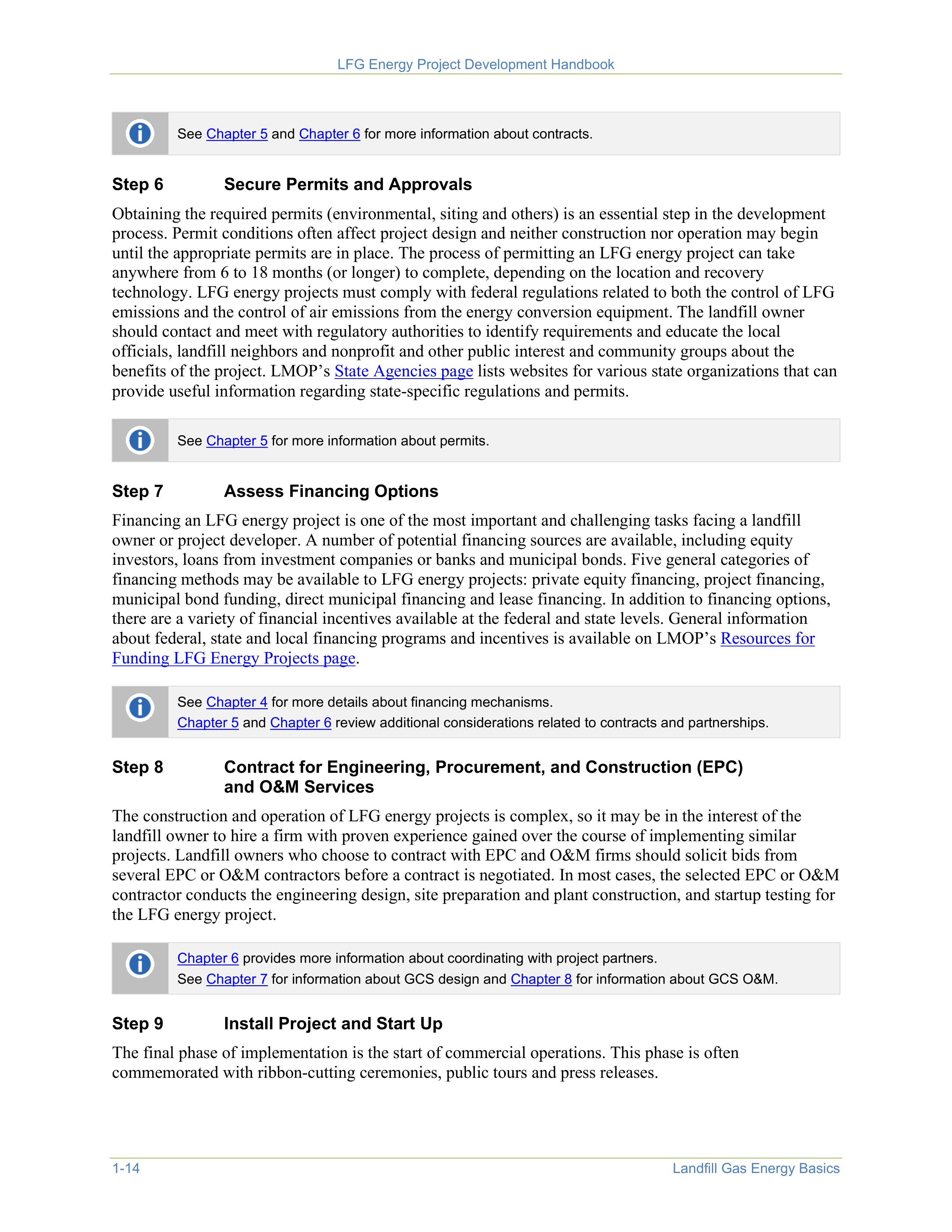
Step 2
Evaluate Project Economics
The next step is to perform a detailed economic assessment of converting LFG into a marketable energy
product such as electricity, steam, RNG, vehicle fuel or boiler fuel. A variety of technologies can be used
to maximize the value of LFG. The best configuration for a particular landfill will depend on a number of
factors, including the existence of an available energy market, project costs, potential revenue sources and
other technical considerations. LMOP’s Landfill Gas Energy Cost Model
(
LFGcost-Web)
can help with
preliminary economic evaluation. If a GCS is already installed, this improves the economics for a project.
See
Chapter 3
for details about project technology options.
Chapter 4
outlines the process for assessing project economics and financing options.
Step 3
Establish Project Structure
Implementation of a successful LFG energy project begins with identifying the appropriate management
structure. For example, options for managing an LFG energy project include:
•
The landfill owner develops and manages the project internally.
•
The landfill owner teams with an external project developer so that the developer finances, constructs,
owns and operates the project.
•
The landfill owner teams with partners (such as an equipment supplier or energy end user).
LMOP can assist with project partnering by identifying potential matches and distributing Requests for
Proposals (RFPs).
Chapter 5
provides an overview of the types of contracts used for LFG energy projects.
See
Chapter 6
for more information on project structures and evaluating project partners.
Step 4
Draft Development Contract
The terms of LFG energy project partnerships should be formalized in a development contract. The
contract identifies which partner owns the gas rights and the rights to potential emission reductions and
other environmental attributes. The contract also establishes each partner’s responsibilities, including
design, installation and O&M. Contracting with a developer is a complex issue and each contract will
depend on the specific nature of the project and the objectives and limitations of the participants.
See
Chapter 5
to learn about LFG energy project contracts and permitting requirements.
See
Chapter 6
for details about selecting project partners.
Step 5
Negotiate Energy Sales Contract (Off-Take Agreement)
The LFG energy project owner and the end user negotiate an energy sales contract that specifies the amount
of the commodity (e.g., gas, power) to be delivered by the project owner to the end user and the price to be
paid by the end user for that commodity. The terms of the energy sales contract typically dictate the success
or failure of the LFG energy project because they secure the project’s source of revenue. Therefore,
successfully obtaining this contract is a crucial milestone in the project development process. Negotiating
an energy sales contract involves the following actions: evaluating the end user’s need, preparing a draft
offer contract, developing the project design and pricing, preparing and presenting a bid package, reviewing
contract terms and conditions, and signing the contract. Because contract negotiation is often a complex
process, owners and developers should consult an expert for further information and guidance.

LFG Energy Project Development Handbook
1-14
Landfill Gas Energy Basics
See
Chapter 5
and
Chapter 6
for more information about contracts.
Step 6
Secure Permits and Approvals
Obtaining the required permits (environmental, siting and others) is an essential step in the development
process. Permit conditions often affect project design and neither construction nor operation may begin
until the appropriate permits are in place. The process of permitting an LFG energy project can take
anywhere from 6 to 18 months (or longer) to complete, depending on the location and recovery
technology. LFG energy projects must comply with federal regulations related to both the control of LFG
emissions and the control of air emissions from the energy conversion equipment. The landfill owner
should contact and meet with regulatory authorities to identify requirements and educate the local
officials, landfill neighbors and nonprofit and other public interest and community groups about the
benefits of the project. LMOP’s
State Agencies page
lists websites for various state organizations that can
provide useful information regarding state-specific regulations and permits.
See
Chapter 5
for more information about permits.
Step 7
Assess Financing Options
Financing an LFG energy project is one of the most important and challenging tasks facing a landfill
owner or project developer. A number of potential financing sources are available, including equity
investors, loans from investment companies or banks and municipal bonds. Five general categories of
financing methods may be available to LFG energy projects: private equity financing, project financing,
municipal bond funding, direct municipal financing and lease financing. In addition to financing options,
there are a variety of financial incentives available at the federal and state levels. General information
about federal, state and local financing programs and incentives is available on LMOP’s
Resources for
Funding LFG Energy Projects page
.
See
Chapter 4
for more details about financing mechanisms.
Chapter 5
and
Chapter 6
review additional considerations related to contracts and partnerships.
Step 8
Contract for Engineering, Procurement, and Construction (EPC)
and O&M Services
The construction and operation of LFG energy projects is complex, so it may be in the interest of the
landfill owner to hire a firm with proven experience gained over the course of implementing similar
projects. Landfill owners who choose to contract with EPC and O&M firms should solicit bids from
several EPC or O&M contractors before a contract is negotiated. In most cases, the selected EPC or O&M
contractor conducts the engineering design, site preparation and plant construction, and startup testing for
the LFG energy project.
Chapter 6
provides more information about coordinating with project partners.
See
Chapter 7
for information about GCS design and
Chapter 8
for information about GCS O&M.
Step 9
Install Project and Start Up
The final phase of implementation is the start of commercial operations. This phase is often
commemorated with ribbon-cutting ceremonies, public tours and press releases.

Landfill Gas Modeling
2-1
Landfill gas (LFG) modeling is the practice of forecasting gas generation and recovery based on past and
future waste disposal histories and estimates of gas collection system (GCS) efficiency. It is an important
step in the project development process because it provides an estimate of the amount of recoverable LFG
that will be generated over time. LFG modeling is performed for regulatory and non-regulatory purposes.
Regulatory applications
of LFG models are conducted for landfills in the United States to establish the
requirements for installation and operation of the gas collection and control system (GCCS).
Non-
regulatory applications
of LFG models typically include any of the following:
•
Evaluating the feasibility of an LFG energy project
•
Determining GCCS design requirements
•
Performing due diligence evaluations of potential or actual project performance
This chapter covers non-regulatory LFG modeling applications only. EPA does not intend for the material
presented in this handbook to supersede or replace required procedures for preparing LFG models for
regulatory purposes. Federal regulations such as the New Source Performance Standards (NSPS) require
modeling to evaluate the applicability of and compliance with rules. EPA’s Greenhouse Gas Reporting
Program (GHGRP) has a separate set of modeling equations and parameters to estimate methane
emissions for annual reporting purposes. For regulatory applications, the modeler must use the specific
procedures, default values and test methods prescribed in the rule.
Refer to the appropriate regulations for details, for example, the
NSPS [40 CFR part 60, subpart XXX]
and related documentation
and
GHGRP 40 CFR part 98 subpart HH
.
2.1 Introduction to LandGEM
The first-order decay
rate equation produces
an estimate for the
amount of methane that
will be generated at a
specific time.
EPA’s Landfill Gas Emissions Model (LandGEM) is a Microsoft Excel-
based software application that uses a first-order decay rate equation to
calculate estimates for methane and LFG generation. LandGEM is the most
widely used LFG model and is the industry standard for regulatory and
non-regulatory applications in the United States.
LandGEM (v. 3.03)
was released by EPA in June 2020.
The First-Order Decay Equation
LandGEM uses the first-order decay equation below to estimate methane generation. LFG generation
estimates are based on the methane content of the LFG. The default methane content of LFG is 50
percent, which is both the industry standard value and the Landfill Methane Outreach Program (LMOP)’s
recommended default value.
LFG Energy Project Development Handbook
2-2
Landfill Gas Modeling
Q
CH4
=
∑∑
=
=
n
i
j
1
1
1.0
k L
0
(M
i
/10) (e
-ktij
)
Where:
Q
CH4
=
estimated methane generation flow rate (in cubic meters [m
3
] per year or average cubic
feet per minute [cfm])
i
=
1-year time increment
n
=
(year of the calculation) – (initial year of waste acceptance)
j
=
0.1-year time increment
k
=
methane generation rate constant (1/year)
L
0
=
potential methane generation capacity (m
3
per megagram [Mg] or cubic feet per ton)
M
i
=
mass of solid waste disposed in the i
th
year (Mg or ton)
t
ij
=
age of the j
th
section of waste mass disposed in the i
th
year (decimal years)
LandGEM assumes that methane generation is at its peak shortly after initial waste placement (after a
short time lag while anaerobic conditions are established in the landfill). The model also assumes that the
rate of landfill methane generation then decreases exponentially (first-order decay) as organic material is
consumed by bacteria.
Model Inputs
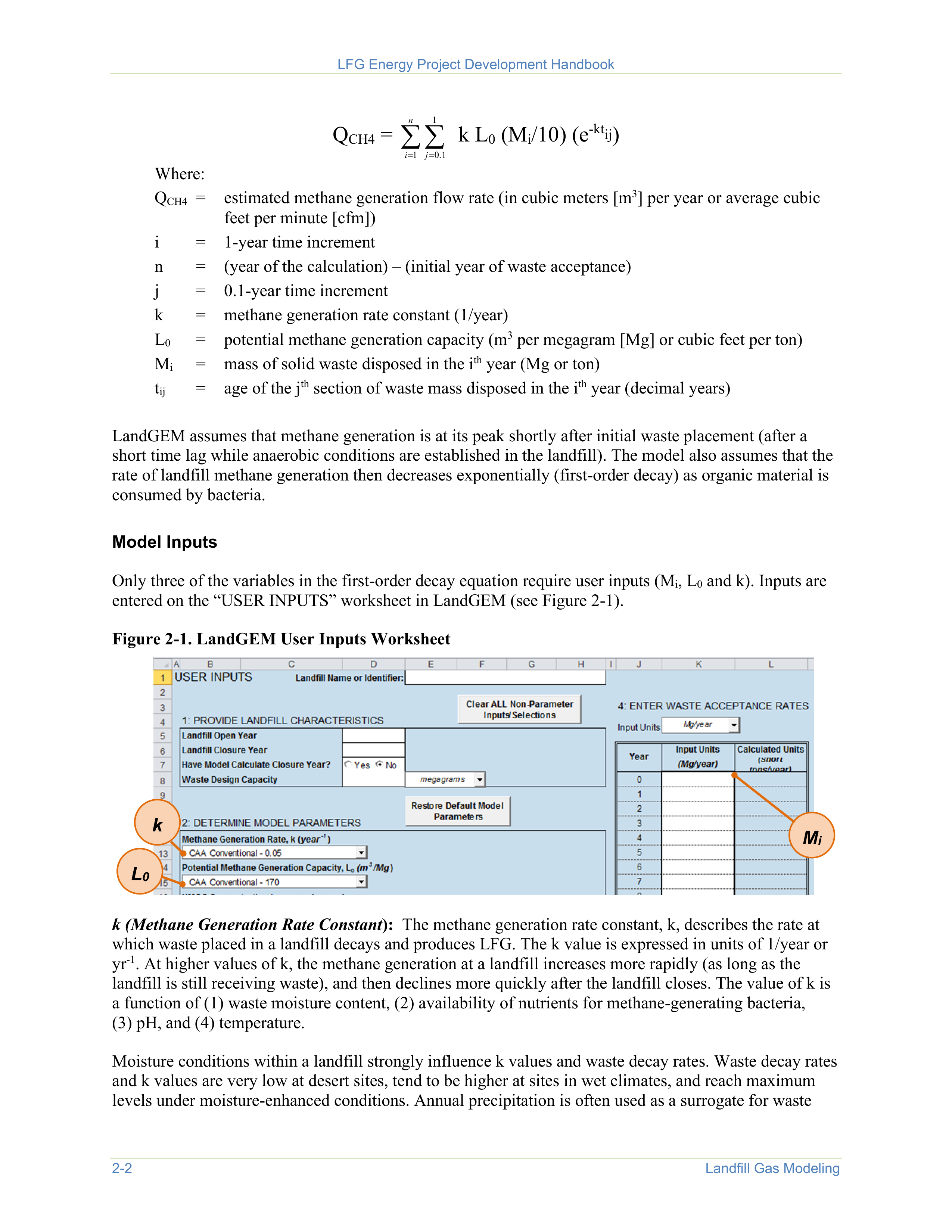
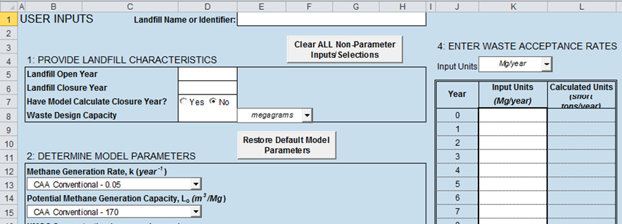
Only three of the variables in the first-order decay equation require user inputs (M
i
, L
0
and k). Inputs are
entered on the “USER INPUTS” worksheet in LandGEM (see Figure 2-1).
Figure 2-1. LandGEM User Inputs Worksheet
k
L
0
M
i
k (Methane Generation Rate Constant
):
The methane generation rate constant, k, describes the rate at
which waste placed in a landfill decays and produces LFG. The k value is expressed in units of 1/year or
yr
-1
. At higher values of k, the methane generation at a landfill increases more rapidly (as long as the
landfill is still receiving waste), and then declines more quickly after the landfill closes. The value of k is
a function of (1) waste moisture content, (2) availability of nutrients for methane-generating bacteria,
(3) pH, and (4) temperature.
Moisture conditions within a landfill strongly influence k values and waste decay rates. Waste decay rates
and k values are very low at desert sites, tend to be higher at sites in wet climates, and reach maximum
levels under moisture-enhanced conditions. Annual precipitation is often used as a surrogate for waste
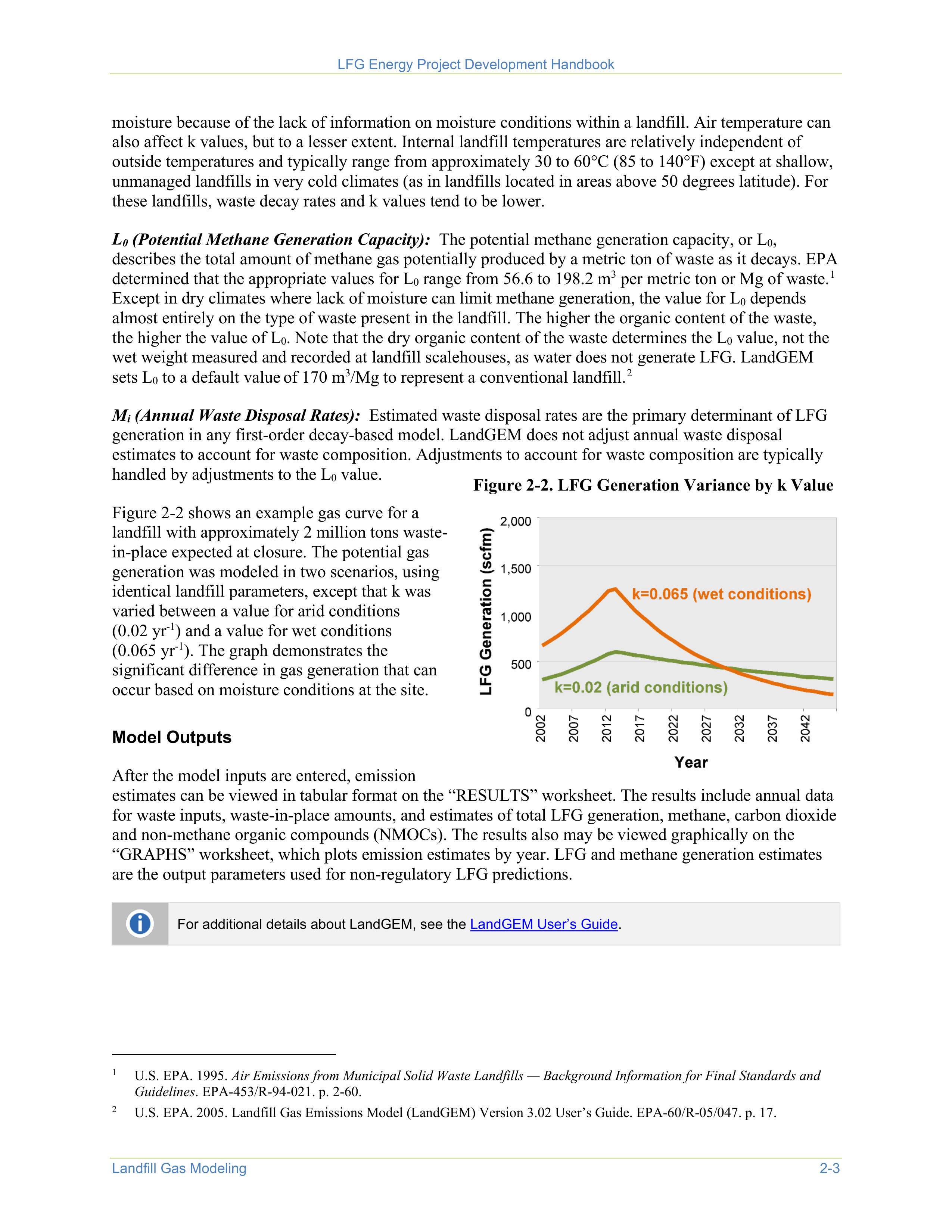
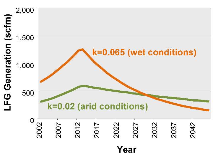

LFG Energy Project Development Handbook
Landfill Gas Modeling
2-3
moisture because of the lack of information on moisture conditions within a landfill. Air temperature can
also affect k values, but to a lesser extent. Internal landfill temperatures are relatively independent of
outside temperatures and typically range from approximately 30 to 60°C (85 to 140°F) except at shallow,
unmanaged landfills in very cold climates (as in landfills located in areas above 50 degrees latitude). For
these landfills, waste decay rates and k values tend to be lower.
L
0
(Potential Methane Generation Capacity):
The potential methane generation capacity, or L
0
,
describes the total amount of methane gas potentially produced by a metric ton of waste as it decays. EPA
determined that the appropriate values for L
0
range from 56.6 to 198.2 m
3
per metric ton or Mg of waste.
1
Except in dry climates where lack of moisture can limit methane generation, the value for L
0
depends
almost entirely on the type of waste present in the landfill. The higher the organic content of the waste,
the higher the value of L
0
. Note that the dry organic content of the waste determines the L
0
value, not the
wet weight measured and recorded at landfill scalehouses, as water does not generate LFG. LandGEM
sets L
0
to a default value
of 170 m
3
/Mg to represent a conventional landfill.
2
1
U.S. EPA. 1995.
Air Emissions from Municipal Solid Waste Landfills — Background Information for Final Standards and
Guidelines
. EPA-453/R-94-021. p. 2-60.
2
U.S. EPA. 2005. Landfill Gas Emissions Model (LandGEM) Version 3.02 User’s Guide. EPA-60/R-05/047. p. 17.
M
i
(Annual Waste Disposal Rates):
Estimated waste disposal rates are the primary determinant of LFG
generation in any first-order decay-based model. LandGEM does not adjust annual waste disposal
estimates to account for waste composition. Adjustments to account for waste composition are typically
handled by adjustments to the L
0
value.
Figure 2-2 shows an example gas curve for a
landfill with approximately 2 million tons waste-
in-place expected at closure. The potential gas
generation was modeled in two scenarios, using
identical landfill parameters, except that k was
varied between a value for arid conditions
(0.02 yr
-1
) and a value for wet conditions
(0.065 yr
-1
). The graph demonstrates the
significant difference in gas generation that can
occur based on moisture conditions at the site.
Figure 2-2. LFG Generation Variance by k Value
Model Outputs
After the model inputs are entered, emission
estimates can be viewed in tabular format on the “RESULTS” worksheet. The results include annual data
for waste inputs, waste-in-place amounts, and estimates of total LFG generation, methane, carbon dioxide
and non-methane organic compounds (NMOCs). The results also may be viewed graphically on the
“GRAPHS” worksheet, which plots emission estimates by year. LFG and methane generation estimates
are the output parameters used for non-regulatory LFG predictions.
For additional details about LandGEM, see the
LandGEM User’s Guide
.
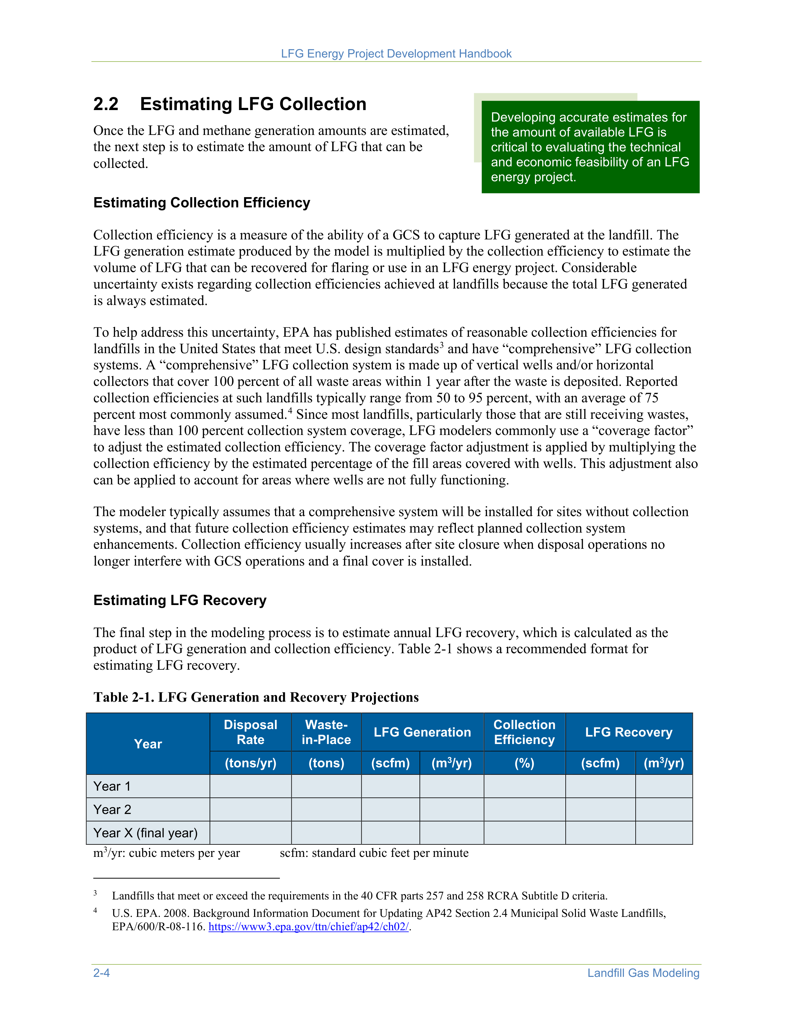
LFG Energy Project Development Handbook
2-4
Landfill Gas Modeling
2.2
Estimating LFG Collection
Once the LFG and methane generation amounts are estimated,
the next step is to estimate the amount of LFG that can be
collected.
Developing accurate estimates for
the amount of available LFG is
critical to evaluating the technical
and economic feasibility of an LFG
energy project.
Estimating Collection Efficiency
Collection efficiency is a measure of the ability of a GCS to capture LFG generated at the landfill. The
LFG generation estimate produced by the model is multiplied by the collection efficiency to estimate the
volume of LFG that can be recovered for flaring or use in an LFG energy project. Considerable
uncertainty exists regarding collection efficiencies achieved at landfills because the total LFG generated
is always estimated.
To help address this uncertainty, EPA has published estimates of reasonable collection efficiencies for
landfills in the United States that meet U.S. design standards
3
and have “comprehensive” LFG collection
systems. A “comprehensive” LFG collection system is made up of vertical wells and/or horizontal
collectors that cover 100 percent of all waste areas within 1 year after the waste is deposited. Reported
collection efficiencies at such landfills typically range from 50 to 95 percent, with an average of 75
percent most commonly assumed.
4
Since most landfills, particularly those that are still receiving wastes,
have less than 100 percent collection system coverage, LFG modelers commonly use a “coverage factor”
to adjust the estimated collection efficiency. The coverage factor adjustment is applied by multiplying the
collection efficiency by the estimated percentage of the fill areas covered with wells. This adjustment also
can be applied to account for areas where wells are not fully functioning.
3
Landfills that meet or exceed the requirements in the 40 CFR parts 257 and 258 RCRA Subtitle D criteria.
4
U.S. EPA. 2008. Background Information Document for Updating AP42 Section 2.4 Municipal Solid Waste Landfills,
EPA/600/R-08-116.
https://www3.epa.gov/ttn/chief/ap42/ch02/
.
The modeler typically assumes that a comprehensive system will be installed for sites without collection
systems, and that future collection efficiency estimates may reflect planned collection system
enhancements. Collection efficiency usually increases after site closure when disposal operations no
longer interfere with GCS operations and a final cover is installed.
Estimating LFG Recovery
The final step in the modeling process is to estimate annual LFG recovery, which is calculated as the
product of LFG generation and collection efficiency. Table 2-1 shows a recommended format for
estimating LFG recovery.
Table 2-1. LFG Generation and Recovery Projections
Year
Disposal
Rate
Waste-
in-Place
LFG Generation
Collection
Efficiency
LFG Recovery
(tons/yr)
(tons)
(scfm)
(m
3
/yr)
(%)
(scfm)
(m
3
/yr)
Year 1
Year 2
Year X (final year)
m
3
/yr: cubic meters per year
scfm: standard cubic feet per minute
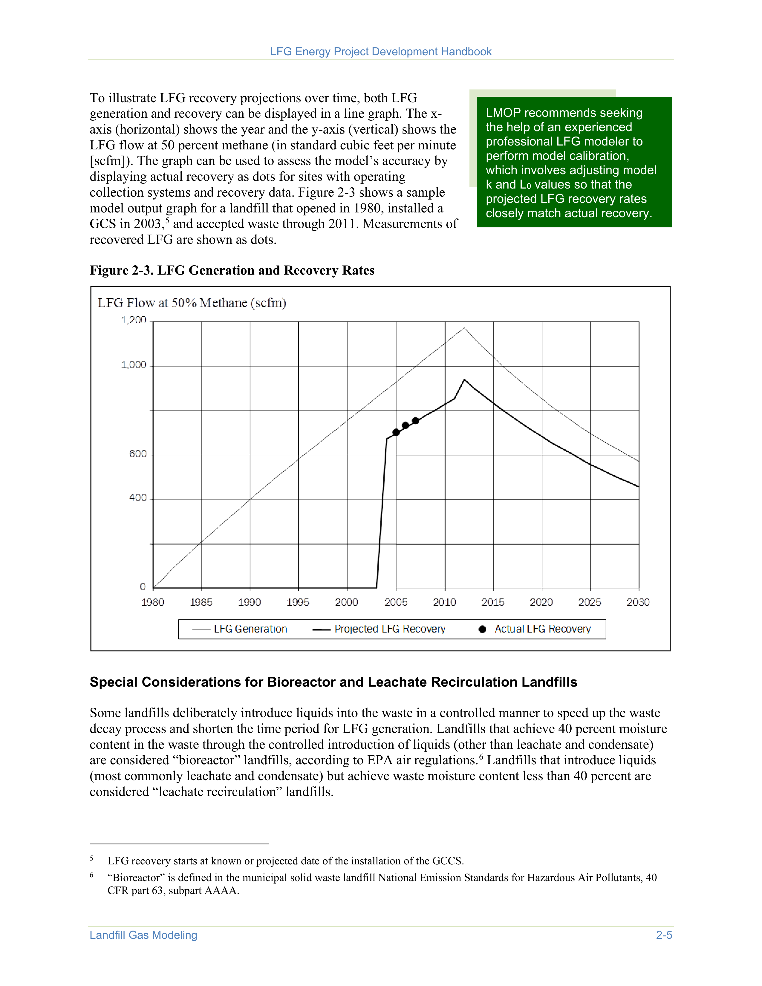
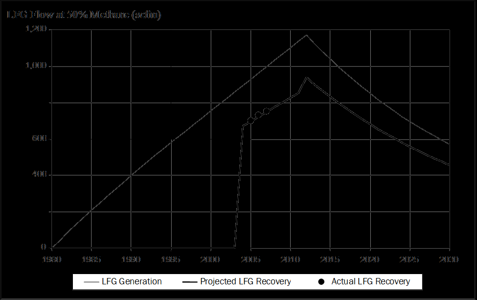
LFG Energy Project Development Handbook
Landfill Gas Modeling
2-5
LMOP recommends seeking
the help of an experienced
professional LFG modeler to
perform model calibration,
which involves adjusting model
k and L
0
values so that the
projected LFG recovery rates
closely match actual recovery.
To illustrate LFG recovery projections over time, both LFG
generation and recovery can be displayed in a line graph. The x-
axis (horizontal) shows the year and the y-axis (vertical) shows the
LFG flow at 50 percent methane (in standard cubic feet per minute
[scfm]). The graph can be used to assess the model’s accuracy by
displaying actual recovery as dots for sites with operating
collection systems and recovery data. Figure 2-3 shows a sample
model output graph for a landfill that opened in 1980, installed a
GCS in 2003,
5
and accepted waste through 2011. Measurements of
recovered LFG are shown as dots.
5
LFG recovery starts at known or projected date of the installation of the GCCS.
Figure 2-3. LFG Generation and Recovery Rates
Special Considerations for Bioreactor and Leachate Recirculation Landfills
Some landfills deliberately introduce liquids into the waste in a controlled manner to speed up the waste
decay process and shorten the time period for LFG generation. Landfills that achieve 40 percent moisture
content in the waste through the controlled introduction of liquids (other than leachate and condensate)
are considered “bioreactor” landfills, according to EPA air regulations.
6
Landfills that introduce liquids
(most commonly leachate and condensate) but achieve waste moisture content less than 40 percent are
considered “leachate recirculation” landfills.
6
“Bioreactor” is defined in the municipal solid waste landfill National Emission Standards for Hazardous Air Pollutants, 40
CFR part 63, subpart AAAA.

LFG Energy Project Development Handbook
2-6
Landfill Gas Modeling
The introduction of liquids into a landfill causes significant increases in waste decay rates and k values.
LFG generation increases more rapidly while the landfill is receiving waste and decreases more rapidly
once disposal stops, but the total LFG generation over the long term remains the same. L
0
values should
not be affected by liquids introduction because only the rate of LFG generation is affected.
•
k value for bioreactor landfills:
LandGEM provides a default k value of 0.7 yr
-1
for modeling
bioreactor landfills (the “inventory wet” value). However, LMOP recommends assigning a k value of
0.3 yr
-1
for bioreactors based on a study conducted by the University of Florida.
7
•
k value for leachate recirculation landfills:
No single k value is recommended or appropriate for
leachate recirculation landfills because the impact of leachate recirculation on LFG generation varies
depending on the amount of liquids added and the moisture content of waste achieved.
7
U.S. EPA. 2005.
First-Order Kinetic Gas Generation Model Parameters for Wet Landfills
. EPA-600/R-05/072.
http://nepis.epa.gov/Adobe/PDF/P100ADRJ.pdf
.
In some instances, only a portion of a landfill’s total site is designed and operated as a bioreactor or
leachate recirculation landfill. In such cases, the bioreactor or leachate recirculation portion should be
modeled separately from the remainder of the site, using waste disposal inputs for these areas only.
Visit EPA’s website to learn more about
bioreactors
.
2.3
Model Limitations
Accurate estimates for LFG recovery are critical to the proper design and financial success of LFG energy
projects. LFG modelers should be aware of factors that can produce error within a model and use
appropriate inputs to avoid significantly overestimating the amount of recoverable LFG. Factors that can
affect the accuracy of LFG recovery projections include:
•
Inaccurate assumptions
.
Inaccurate assumptions about variables such as organic content, future
disposal rates, site closure dates, wellfield buildout, expansion schedules or collection efficiencies can
result in large errors in predicting future recovery.
•
Limited or poor-quality disposal data
.
Significant model error can be introduced if good disposal
data are not available.
•
Poor-quality flow data or inaccurate estimates of collection efficiency used for model calibration.
Model calibration requires both accurate estimates of collection efficiency and good-quality flow data
that are representative of long-term average recovery.
•
Atypical waste composition
.
Waste composition data are often not available to determine if unusual
waste composition is a cause of model inaccuracy. However, the risk can be minimized by
introducing sample collection procedures to better determine waste composition.
•
Limitations because of the structure of LandGEM
.
For example, LandGEM cannot accommodate
changes in k or L
0
values in the same model run. Changing landfill conditions that cannot be modeled
as a result of this limitation include the following:
Application of liquids to existing waste
Variations in waste composition over time
Installation of a geomembrane cover.

Project Technology Options
3-1
The goal of a landfill gas (LFG) energy project is to convert LFG into a useful form of energy. Hundreds
of LFG energy projects currently operate in the United States, involving public and private organizations,
small and large landfills and various types of technologies. The most common LFG energy applications
include:
•
Electricity (power production and combined
heat and power [CHP]) – LFG extracted from
the landfill is converted to electricity;
•
Direct use of medium-British thermal unit
(Btu) gas – treated LFG is used as a direct
source of fuel;
•
Upgrade to renewable natural gas (RNG) –
LFG is cleaned to produce the equivalent of
natural gas, compressed natural gas (CNG) or
liquefied natural gas (LNG).
In CHP applications, LFG is used to produce
electricity and heat. Direct-use applications include
heating greenhouses, firing brick kilns and
providing fuel to chemical and automobile
manufacturing businesses. Table 3-1 provides a
breakdown of technologies used in operational
LFG energy projects in 2021.
The remainder of this chapter provides a brief
overview of design factors and technology options
for LFG energy projects, followed by a discussion
of considerations in technology selection. For
additional information on select technology costs
and emissions, see the report
Evaluating the Air Quality, Climate & Economic Impacts of Biogas
Management Technologies
by EPA’s Office of Research and Development in collaboration with other
programs.
Table 3-1. Operational Project Technologies
Project Technology
Projects
1
Electricity Projects
Internal combustion engine
(reciprocating engine)
296
CHP
43
Gas turbine
29
Microturbine
8
Combined cycle
5
Steam turbine
4
Stirling cycle engine
1
Medium-Btu Direct-use Projects
Boiler
46
Direct thermal
31
Leachate evaporation
12
Greenhouse
4
RNG Projects
Pipeline Injection
62
Local Use
9
1
U.S. EPA LMOP. Landfill and LFG Energy Project Database. March 2021.
For more information about LFG collection, flaring and treatment system components, see
Chapter 1
.
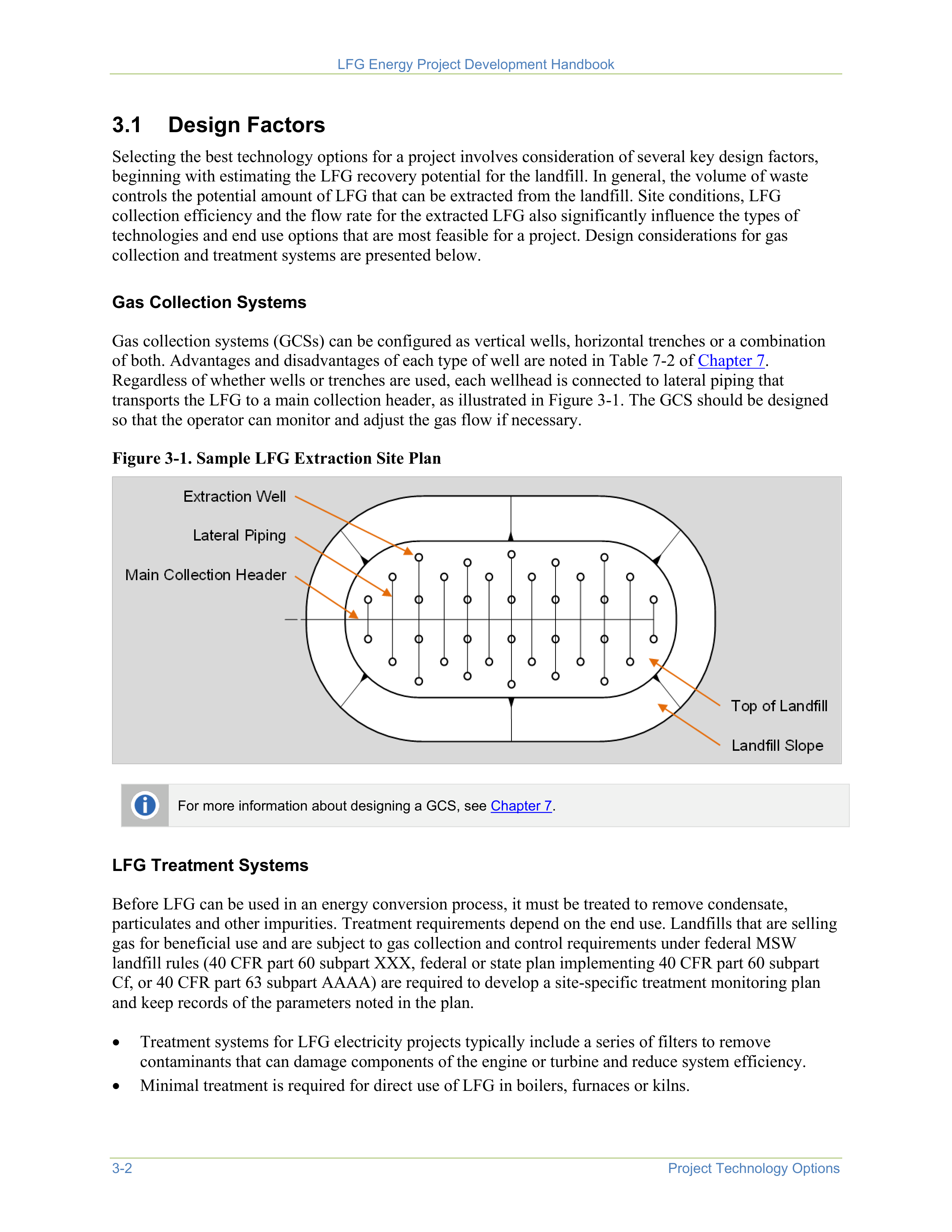
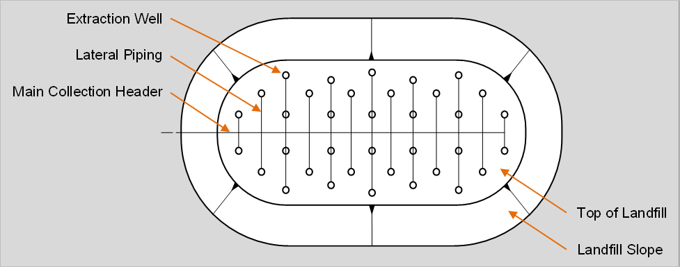

LFG Energy Project Development Handbook
3-2
Project Technology Options
3.1
Design Factors
Selecting the best technology options for a project involves consideration of several key design factors,
beginning with estimating the LFG recovery potential for the landfill. In general, the volume of waste
controls the potential amount of LFG that can be extracted from the landfill. Site conditions, LFG
collection efficiency and the flow rate for the extracted LFG also significantly influence the types of
technologies and end use options that are most feasible for a project. Design considerations for gas
collection and treatment systems are presented below.
Gas Collection Systems
Gas collection systems (GCSs) can be configured as vertical wells, horizontal trenches or a combination
of both. Advantages and disadvantages of each type of well are noted in Table 7-2 of
Chapter 7
.
Regardless of whether wells or trenches are used, each wellhead is connected to lateral piping that
transports the LFG to a main collection header, as illustrated in Figure 3-1. The GCS should be designed
so that the operator can monitor and adjust the gas flow if necessary.
Figure 3-1. Sample LFG Extraction Site Plan
For more information about designing a GCS, see
Chapter 7
.
LFG Treatment Systems
Before LFG can be used in an energy conversion process, it must be treated to remove condensate,
particulates and other impurities. Treatment requirements depend on the end use. Landfills that are selling
gas for beneficial use and are subject to gas collection and control requirements under federal MSW
landfill rules (40 CFR part 60 subpart XXX, federal or state plan implementing 40 CFR part 60 subpart
Cf, or 40 CFR part 63 subpart AAAA) are required to develop a site-specific treatment monitoring plan
and keep records of the parameters noted in the plan.
•
Treatment systems for LFG electricity projects typically include a series of filters to remove
contaminants that can damage components of the engine or turbine and reduce system efficiency.
•
Minimal treatment is required for direct use of LFG in boilers, furnaces or kilns.
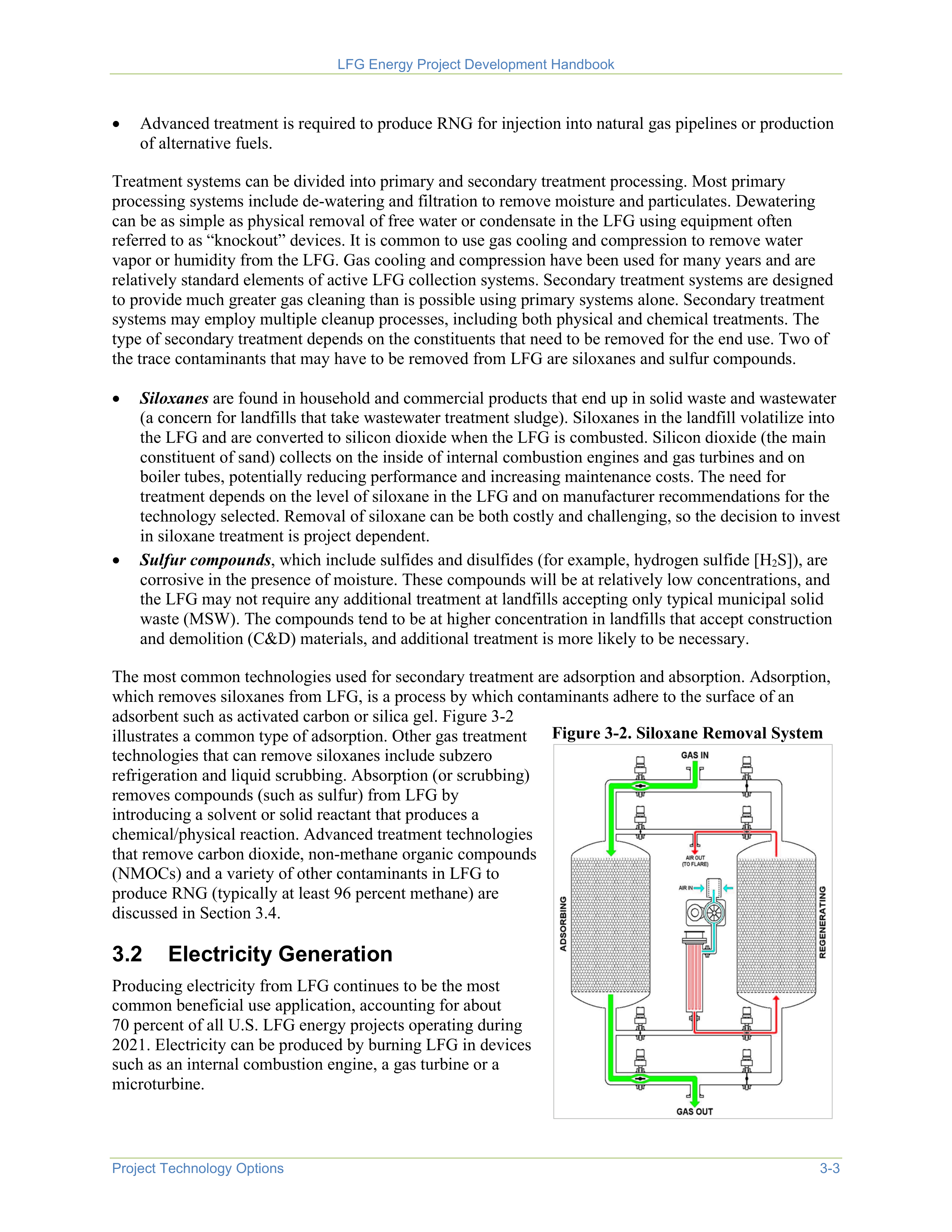
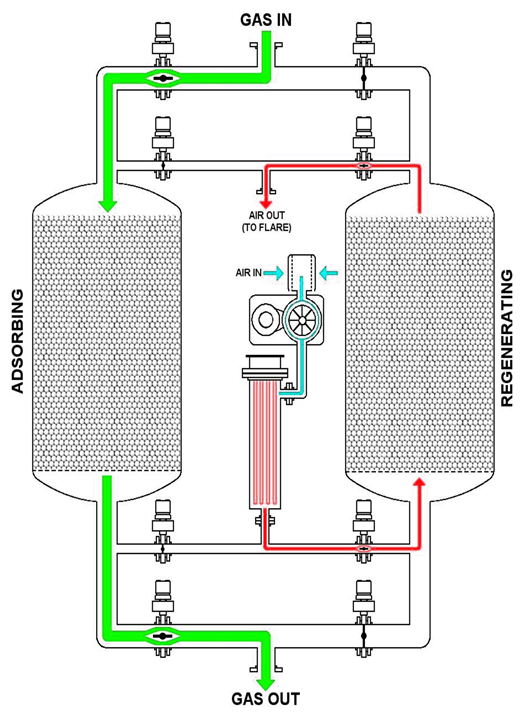
LFG Energy Project Development Handbook
Project Technology Options
3-3
•
Advanced treatment is required to produce RNG for injection into natural gas pipelines or production
of alternative fuels.
Treatment systems can be divided into primary and secondary treatment processing. Most primary
processing systems include de-watering and filtration to remove moisture and particulates. Dewatering
can be as simple as physical removal of free water or condensate in the LFG using equipment often
referred to as “knockout” devices. It is common to use gas cooling and compression to remove water
vapor or humidity from the LFG. Gas cooling and compression have been used for many years and are
relatively standard elements of active LFG collection systems. Secondary treatment systems are designed
to provide much greater gas cleaning than is possible using primary systems alone. Secondary treatment
systems may employ multiple cleanup processes, including both physical and chemical treatments. The
type of secondary treatment depends on the constituents that need to be removed for the end use. Two of
the trace contaminants that may have to be removed from LFG are siloxanes and sulfur compounds.
•
Siloxanes
are found in household and commercial products that end up in solid waste and wastewater
(a concern for landfills that take wastewater treatment sludge). Siloxanes in the landfill volatilize into
the LFG and are converted to silicon dioxide when the LFG is combusted. Silicon dioxide (the main
constituent of sand) collects on the inside of internal combustion engines and gas turbines and on
boiler tubes, potentially reducing performance and increasing maintenance costs. The need for
treatment depends on the level of siloxane in the LFG and on manufacturer recommendations for the
technology selected. Removal of siloxane can be both costly and challenging, so the decision to invest
in siloxane treatment is project dependent.
•
Sulfur compounds
, which include sulfides and disulfides (for example, hydrogen sulfide [H
2
S]), are
corrosive in the presence of moisture. These compounds will be at relatively low concentrations, and
the LFG may not require any additional treatment at landfills accepting only typical municipal solid
waste (MSW). The compounds tend to be at higher concentration in landfills that accept construction
and demolition (C&D) materials, and additional treatment is more likely to be necessary.
The most common technologies used for secondary treatment are adsorption and absorption. Adsorption,
which removes siloxanes from LFG, is a process by which contaminants adhere to the surface of an
adsorbent such as activated carbon or silica gel. Figure 3-2
illustrates a common type of adsorption. Other gas treatment
technologies that can remove siloxanes include subzero
refrigeration and liquid scrubbing. Absorption (or scrubbing)
removes compounds (such as sulfur) from LFG by
introducing a solvent or solid reactant that produces a
chemical/physical reaction. Advanced treatment technologies
that remove carbon dioxide, non-methane organic compounds
(NMOCs) and a variety of other contaminants in LFG to
produce RNG (typically at least 96 percent methane) are
discussed in Section 3.4.
Figure 3-2. Diagram of a siloxane removal system.
3.2
Electricity Generation
Producing electricity from LFG continues to be the most
common beneficial use application, accounting for about
70 percent of all U.S. LFG energy projects operating during
2021. Electricity can be produced by burning LFG in devices
such as an internal combustion engine, a gas turbine or a
microturbine.
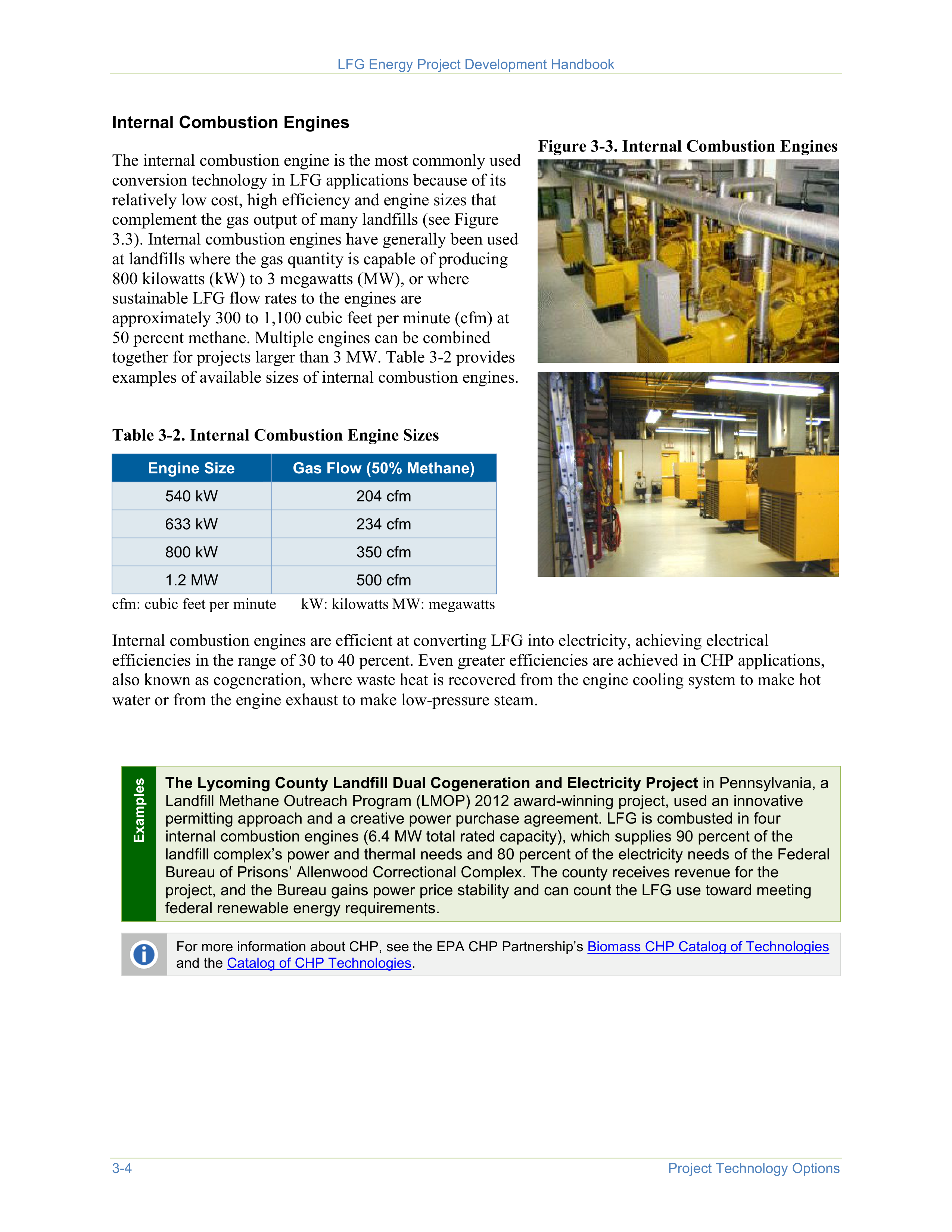
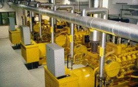
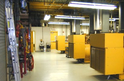

LFG Energy Project Development Handbook
3-4
Project Technology Options
Internal Combustion Engines
The internal combustion engine is the most commonly used
conversion technology in LFG applications because of its
relatively low cost, high efficiency and engine sizes that
complement the gas output of many landfills (see Figure
3.3). Internal combustion engines have generally been used
at landfills where the gas quantity is capable of producing
800 kilowatts (kW) to 3 megawatts (MW), or where
sustainable LFG flow rates to the engines are
approximately 300 to 1,100 cubic feet per minute (cfm) at
50 percent methane. Multiple engines can be combined
together for projects larger than 3 MW. Table 3-2 provides
examples of available sizes of internal combustion engines.
Figure 3-3. Internal Combustion Engines
Table 3-2. Internal Combustion Engine Sizes
Engine Size
Gas Flow (50% Methane)
540 kW
204 cfm
633 kW
234 cfm
800 kW
350 cfm
1.2 MW
500 cfm
cfm: cubic feet per minute
kW: kilowatts MW: megawatts
Internal combustion engines are efficient at converting LFG into electricity, achieving electrical
efficiencies in the range of 30 to 40 percent. Even greater efficiencies are achieved in CHP applications,
also known as cogeneration, where waste heat is recovered from the engine cooling system to make hot
water or from the engine exhaust to make low-pressure steam.
Examples
The Lycoming County Landfill Dual Cogeneration and Electricity Project
in Pennsylvania, a
Landfill Methane Outreach Program (LMOP) 2012 award-winning project, used an innovative
permitting approach and a creative power purchase agreement. LFG is combusted in four
internal combustion engines (6.4 MW total rated capacity), which supplies 90 percent of the
landfill complex’s power and thermal needs and 80 percent of the electricity needs of the Federal
Bureau of Prisons’ Allenwood Correctional Complex. The county receives revenue for the
project, and the Bureau gains power price stability and can count the LFG use toward meeting
federal renewable energy requirements.
For more information about CHP, see the EPA CHP Partnership’s
Biomass CHP Catalog of Technologies
and the
Catalog of CHP Technologies
.
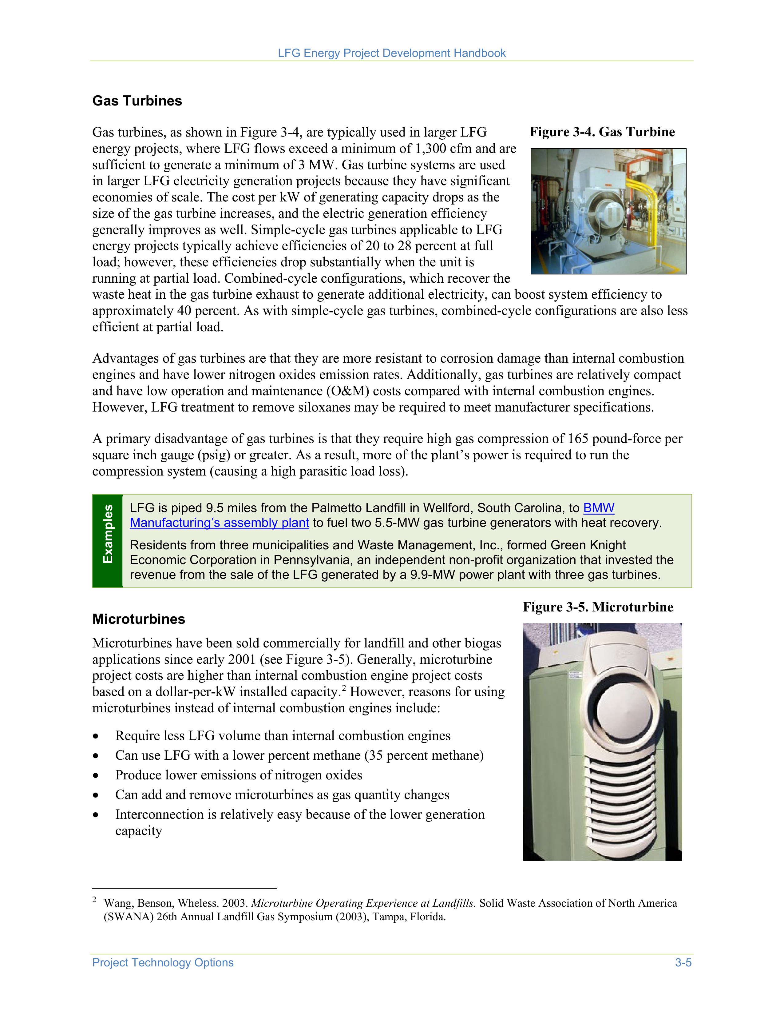
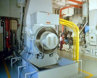

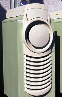
LFG Energy Project Development Handbook
Project Technology Options
3-5
Gas Turbines
Gas turbines, as shown in Figure 3-4, are typically used in larger LFG
energy projects, where LFG flows exceed a minimum of 1,300 cfm and are
sufficient to generate a minimum of 3 MW. Gas turbine systems are used
in larger LFG electricity generation projects because they have significant
economies of scale. The cost per kW of generating capacity drops as the
size of the gas turbine increases, and the electric generation efficiency
generally improves as well. Simple-cycle gas turbines applicable to LFG
energy projects typically achieve efficiencies of 20 to 28 percent at full
load; however, these efficiencies drop substantially when the unit is
running at partial load. Combined-cycle configurations, which recover the
waste heat in the gas turbine exhaust to generate additional electricity, can boost system efficiency to
approximately 40 percent. As with simple-cycle gas turbines, combined-cycle configurations are also less
efficient at partial load.
Figure 3-4. Gas Turbine
Advantages of gas turbines are that they are more resistant to corrosion damage than internal combustion
engines and have lower nitrogen oxides emission rates. Additionally, gas turbines are relatively compact
and have low operation and maintenance (O&M) costs compared with internal combustion engines.
However, LFG treatment to remove siloxanes may be required to meet manufacturer specifications.
A primary disadvantage of gas turbines is that they require high gas compression of 165 pound-force per
square inch gauge (psig) or greater. As a result, more of the plant’s power is required to run the
compression system (causing a high parasitic load loss).
Examples
LFG is piped 9.5 miles from the Palmetto Landfill in Wellford, South Carolina, to
BMW
Manufacturing’s assembly plant
to fuel two 5.5-MW gas turbine generators with heat recovery.
Residents from three municipalities and Waste Management, Inc., formed Green Knight
Economic Corporation in Pennsylvania, an independent non-profit organization that invested the
revenue from the sale of the LFG generated by a 9.9-MW power plant with three gas turbines.
Microturbines
Microturbines have been sold commercially for landfill and other biogas
applications since early 2001 (see Figure 3-5). Generally, microturbine
project costs are higher than internal combustion engine project costs
based on a dollar-per-kW installed capacity.
2
However, reasons for using
microturbines instead of internal combustion engines include:
•
Require less LFG volume than internal combustion engines
•
Can use LFG with a lower percent methane (35 percent methane)
•
Produce lower emissions of nitrogen oxides
•
Can add and remove microturbines as gas quantity changes
•
Interconnection is relatively easy because of the lower generation
capacity
2
Wang, Benson, Wheless. 2003.
Microturbine Operating Experience at Landfills.
Solid Waste Association of North America
(SWANA) 26th Annual Landfill Gas Symposium (2003), Tampa, Florida.
Figure 3-5. Microturbine
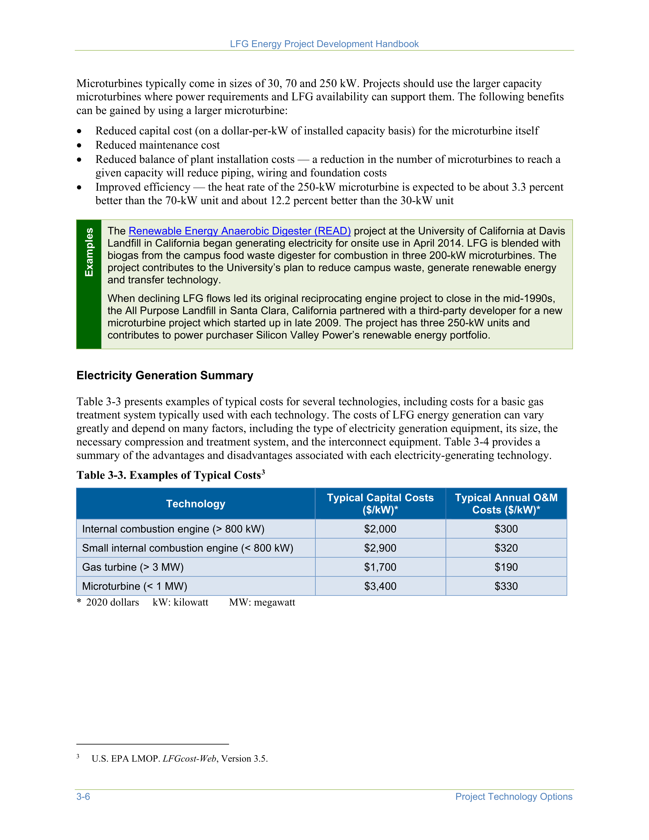
LFG Energy Project Development Handbook
3-6
Project Technology Options
Microturbines typically come in sizes of 30, 70 and 250 kW. Projects should use the larger capacity
microturbines where power requirements and LFG availability can support them. The following benefits
can be gained by using a larger microturbine:
•
Reduced capital cost (on a dollar-per-kW of installed capacity basis) for the microturbine itself
•
Reduced maintenance cost
•
Reduced balance of plant installation costs — a reduction in the number of microturbines to reach a
given capacity will reduce piping, wiring and foundation costs
•
Improved efficiency — the heat rate of the 250-kW microturbine is expected to be about 3.3 percent
better than the 70-kW unit and about 12.2 percent better than the 30-kW unit
Examples
The
Renewable Energy Anaerobic Digester (READ)
project at the University of California at Davis
Landfill in California began generating electricity for onsite use in April 2014. LFG is blended with
biogas from the campus food waste digester for combustion in three 200-kW microturbines. The
project contributes to the University’s plan to reduce campus waste, generate renewable energy
and transfer technology.
When declining LFG flows led its original reciprocating engine project to close in the mid-1990s,
the All Purpose Landfill in Santa Clara, California partnered with a third-party developer for a new
microturbine project which started up in late 2009. The project has three 250-kW units and
contributes to power purchaser Silicon Valley Power’s renewable energy portfolio.
Electricity Generation Summary
Table 3-3 presents examples of typical costs for several technologies, including costs for a basic gas
treatment system typically used with each technology. The costs of LFG energy generation can vary
greatly and depend on many factors, including the type of electricity generation equipment, its size, the
necessary compression and treatment system, and the interconnect equipment. Table 3-4 provides a
summary of the advantages and disadvantages associated with each electricity-generating technology.
Table 3-3. Examples of Typical Costs
3
3
U.S. EPA LMOP.
LFGcost-Web
, Version 3.5.
Technology
Typical Capital Costs
($/kW)*
Typical Annual O&M
Costs ($/kW)*
Internal combustion engine (> 800 kW)
$2,000
$300
Small internal combustion engine (< 800 kW)
$2,900
$320
Gas turbine (> 3 MW)
$1,700
$190
Microturbine (< 1 MW)
$3,400
$330
* 2020 dollars
kW: kilowatt
MW: megawatt
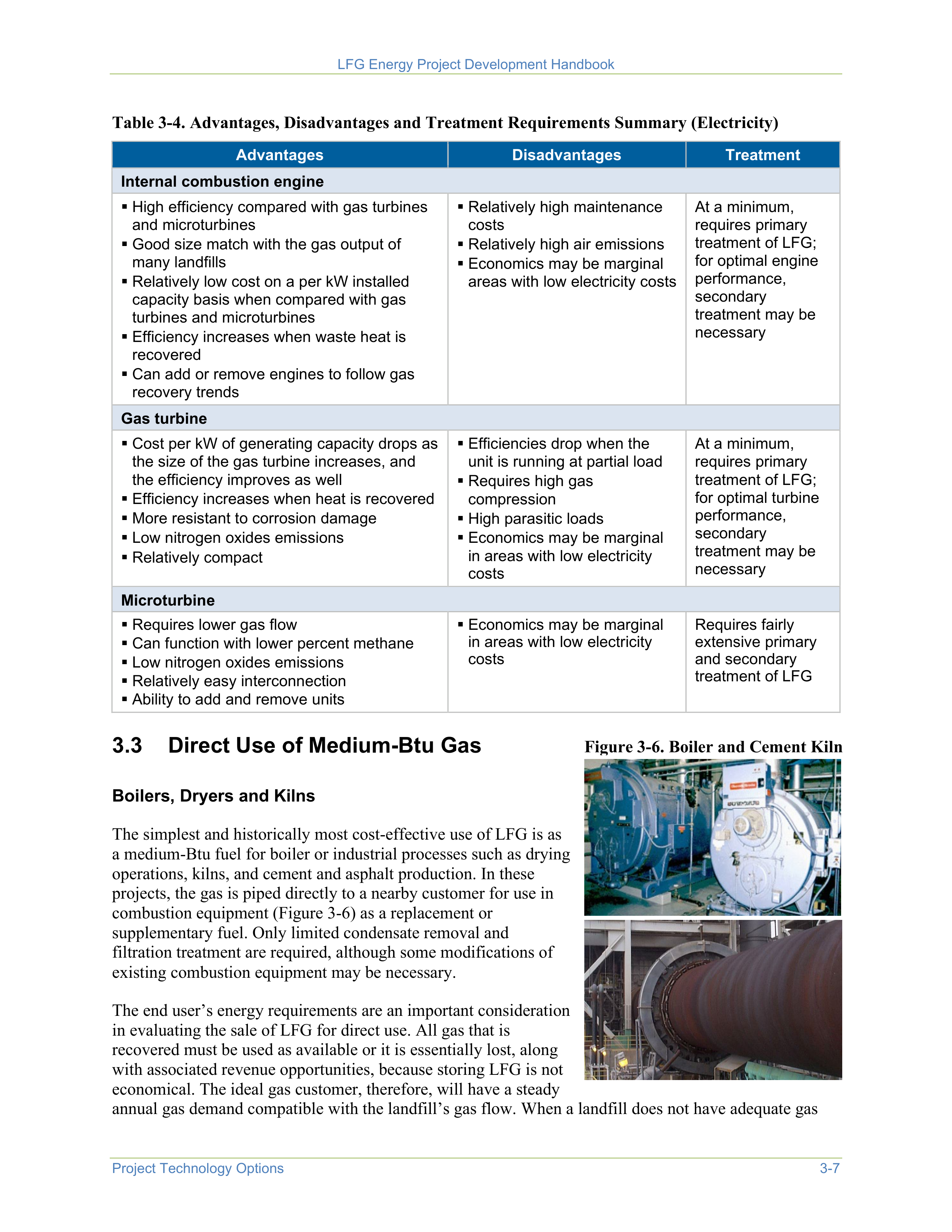

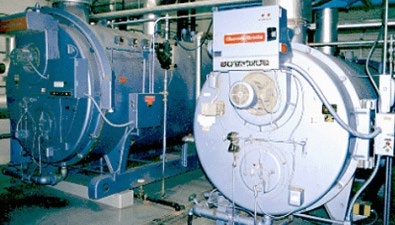
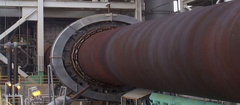
LFG Energy Project Development Handbook
Project Technology Options
3-7
Table 3-4. Advantages, Disadvantages and Treatment Requirements Summary (Electricity)
Advantages
Disadvantages
Treatment
Internal combustion engine
High efficiency compared with gas turbines
and microturbines
Good size match with the gas output of
many landfills
Relatively low cost on a per kW installed
capacity basis when compared with gas
turbines and microturbines
Efficiency increases when waste heat is
recovered
Can add or remove engines to follow gas
recovery trends
Relatively high maintenance
costs
Relatively high air emissions
Economics may be marginal
areas with low electricity costs
At a minimum,
requires primary
treatment of LFG;
for optimal engine
performance,
secondary
treatment may be
necessary
Gas turbine
Cost per kW of generating capacity drops as
the size of the gas turbine increases, and
the efficiency improves as well
Efficiency increases when heat is recovered
More resistant to corrosion damage
Low nitrogen oxides emissions
Relatively compact
Efficiencies drop when the
unit is running at partial load
Requires high gas
compression
High parasitic loads
Economics may be marginal
in areas with low electricity
costs
At a minimum,
requires primary
treatment of LFG;
for optimal turbine
performance,
secondary
treatment may be
necessary
Microturbine
Requires lower gas flow
Can function with lower percent methane
Low nitrogen oxides emissions
Relatively easy interconnection
Ability to add and remove units
Economics may be marginal
in areas with low electricity
costs
Requires fairly
extensive primary
and secondary
treatment of LFG
3.3
Direct Use of Medium-Btu Gas
Boilers, Dryers and Kilns
The simplest and historically most cost-effective use of LFG is as
a medium-Btu fuel for boiler or industrial processes such as drying
operations, kilns, and cement and asphalt production. In these
projects, the gas is piped directly to a nearby customer for use in
combustion equipment (Figure 3-6) as a replacement or
supplementary fuel. Only limited condensate removal and
filtration treatment are required, although some modifications of
existing combustion equipment may be necessary.
Figure 3-6. Boiler and Cement Kiln
The end user’s energy requirements are an important consideration
in evaluating the sale of LFG for direct use. All gas that is
recovered must be used as available or it is essentially lost, along
with associated revenue opportunities, because storing LFG is not
economical. The ideal gas customer, therefore, will have a steady
annual gas demand compatible with the landfill’s gas flow. When a landfill does not have adequate gas
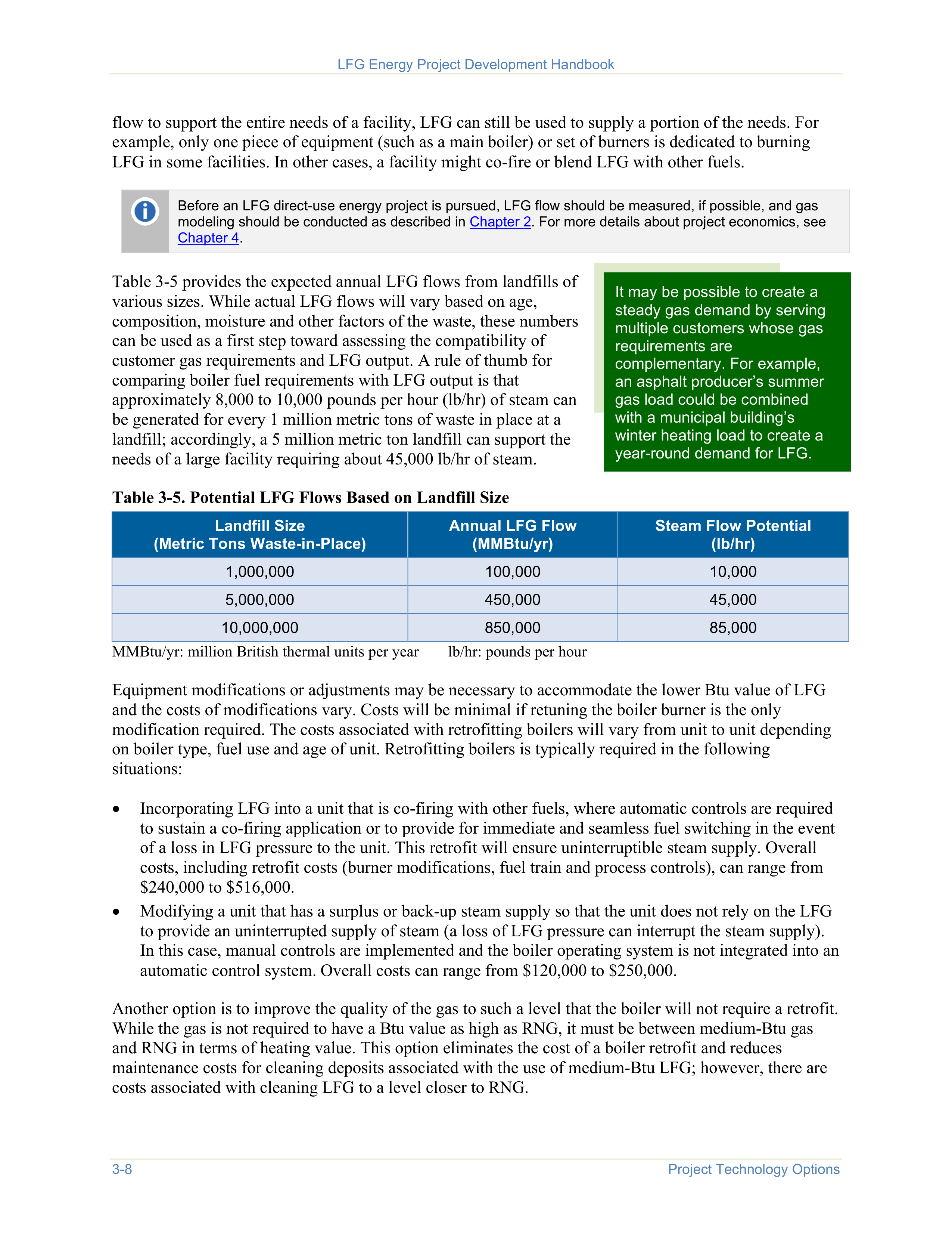



LFG Energy Project Development Handbook
3-8
Project Technology Options
flow to support the entire needs of a facility, LFG can still be used to supply a portion of the needs. For
example, only one piece of equipment (such as a main boiler) or set of burners is dedicated to burning
LFG in some facilities. In other cases, a facility might co-fire or blend LFG with other fuels.
Before an LFG direct-use energy project is pursued, LFG flow should be measured, if possible, and gas
modeling should be conducted as described in
Chapter 2
. For more details about project economics, see
Chapter 4
.
Table 3-5 provides the expected annual LFG flows from landfills of
various sizes. While actual LFG flows will vary based on age,
composition, moisture and other factors of the waste, these numbers
can be used as a first step toward assessing the compatibility of
customer gas requirements and LFG output. A rule of thumb for
comparing boiler fuel requirements with LFG output is that
approximately 8,000 to 10,000 pounds per hour (lb/hr) of steam can
be generated for every 1 million metric tons of waste in place at a
landfill; accordingly, a 5 million metric ton landfill can support the
needs of a large facility requiring about 45,000 lb/hr of steam.
It may be possible to create a
steady gas demand by serving
multiple customers whose gas
requirements are
complementary. For example,
an asphalt producer’s summer
gas load could be combined
with a municipal building’s
winter heating load to create a
year-round demand for LFG.
Table 3-5. Potential LFG Flows Based on Landfill Size
Landfill Size
(Metric Tons Waste-in-Place)
Annual LFG Flow
(MMBtu/yr)
Steam Flow Potential
(lb/hr)
1,000,000
100,000
10,000
5,000,000
450,000
45,000
10,000,000
850,000
85,000
MMBtu/yr: million British thermal units per year
lb/hr: pounds per hour
Equipment modifications or adjustments may be necessary to accommodate the lower Btu value of LFG
and the costs of modifications vary. Costs will be minimal if retuning the boiler burner is the only
modification required. The costs associated with retrofitting boilers will vary from unit to unit depending
on boiler type, fuel use and age of unit. Retrofitting boilers is typically required in the following
situations:
•
Incorporating LFG into a unit that is co-firing with other fuels, where automatic controls are required
to sustain a co-firing application or to provide for immediate and seamless fuel switching in the event
of a loss in LFG pressure to the unit. This retrofit will ensure uninterruptible steam supply. Overall
costs, including retrofit costs (burner modifications, fuel train and process controls), can range from
$240,000 to $516,000.
•
Modifying a unit that has a surplus or back-up steam supply so that the unit does not rely on the LFG
to provide an uninterrupted supply of steam (a loss of LFG pressure can interrupt the steam supply).
In this case, manual controls are implemented and the boiler operating system is not integrated into an
automatic control system. Overall costs can range from $120,000 to $250,000.
Another option is to improve the quality of the gas to such a level that the boiler will not require a retrofit.
While the gas is not required to have a Btu value as high as RNG, it must be between medium-Btu gas
and RNG in terms of heating value. This option eliminates the cost of a boiler retrofit and reduces
maintenance costs for cleaning deposits associated with the use of medium-Btu LFG; however, there are
costs associated with cleaning LFG to a level closer to RNG.
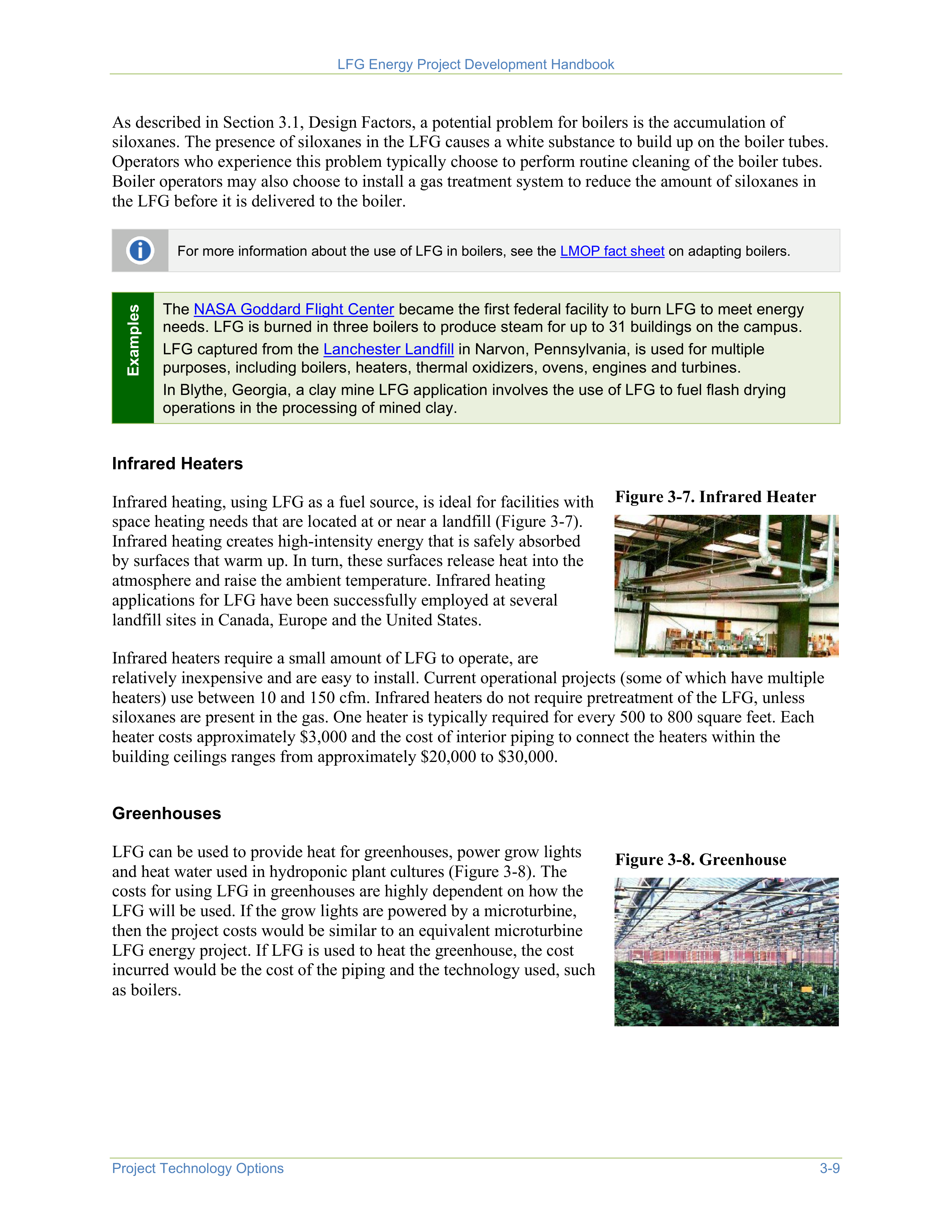

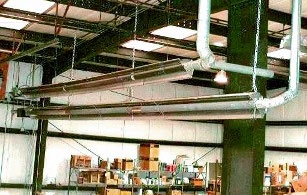
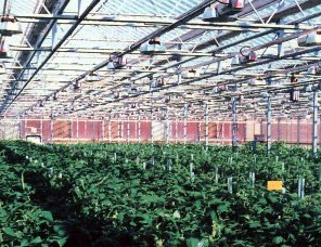
LFG Energy Project Development Handbook
Project Technology Options
3-9
As described in Section 3.1, Design Factors, a potential problem for boilers is the accumulation of
siloxanes. The presence of siloxanes in the LFG causes a white substance to build up on the boiler tubes.
Operators who experience this problem typically choose to perform routine cleaning of the boiler tubes.
Boiler operators may also choose to install a gas treatment system to reduce the amount of siloxanes in
the LFG before it is delivered to the boiler.
For more information about the use of LFG in boilers, see the
LMOP fact sheet
on adapting boilers.
Examples
The
NASA Goddard Flight Center
became the first federal facility to burn LFG to meet energy
needs. LFG is burned in three boilers to produce steam for up to 31 buildings on the campus.
LFG captured from the
Lanchester Landfill
in Narvon, Pennsylvania, is used for multiple
purposes, including boilers, heaters, thermal oxidizers, ovens, engines and turbines.
In Blythe, Georgia, a clay mine LFG application involves the use of LFG to fuel flash drying
operations in the processing of mined clay.
Infrared Heaters
Infrared heating, using LFG as a fuel source, is ideal for facilities with
space heating needs that are located at or near a landfill (Figure 3-7).
Infrared heating creates high-intensity energy that is safely absorbed
by surfaces that warm up. In turn, these surfaces release heat into the
atmosphere and raise the ambient temperature. Infrared heating
applications for LFG have been successfully employed at several
landfill sites in Canada, Europe and the United States.
Figure 3-7. Infrared Heater
Infrared heaters require a small amount of LFG to operate, are
relatively inexpensive and are easy to install. Current operational projects (some of which have multiple
heaters) use between 10 and 150 cfm. Infrared heaters do not require pretreatment of the LFG, unless
siloxanes are present in the gas. One heater is typically required for every 500 to 800 square feet. Each
heater costs approximately $3,000 and the cost of interior piping to connect the heaters within the
building ceilings ranges from approximately $20,000 to $30,000.
Greenhouses
LFG can be used to provide heat for greenhouses, power grow lights
and heat water used in hydroponic plant cultures (Figure 3-8). The
costs for using LFG in greenhouses are highly dependent on how the
LFG will be used. If the grow lights are powered by a microturbine,
then the project costs would be similar to an equivalent microturbine
LFG energy project. If LFG is used to heat the greenhouse, the cost
incurred would be the cost of the piping and the technology used, such
as boilers.
Figure 3-8. Greenhouse
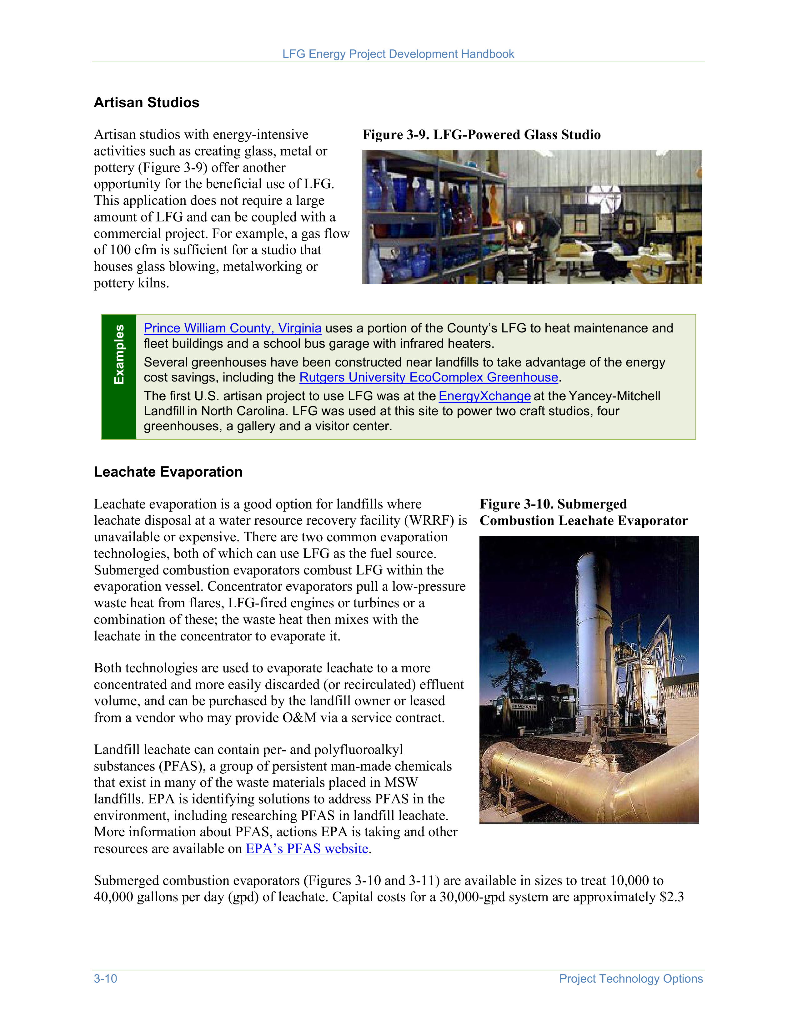

LFG Energy Project Development Handbook
3-10
Project Technology Options
Artisan Studios
Artisan studios with energy-intensive
activities such as creating glass, metal or
pottery (Figure 3-9) offer another
opportunity for the beneficial use of LFG.
This application does not require a large
amount of LFG and can be coupled with a
commercial project. For example, a gas flow
of 100 cfm is sufficient for a studio that
houses glass blowing, metalworking or
pottery kilns.
Figure 3-9. LFG-Powered Glass Studio
Examples
Prince William County, Virginia
uses a portion of the County’s LFG to heat maintenance and
fleet buildings and a school bus garage with infrared heaters.
Several greenhouses have been constructed near landfills to take advantage of the energy
cost savings, including the
Rutgers University EcoComplex Greenhouse
.
The first U.S. artisan project to use LFG was at the
EnergyXchange
at the
Yancey-Mitchell
Landfill
in North Carolina. LFG was used at this site to power two craft studios, four
greenhouses, a gallery and a visitor center.
Leachate Evaporation
Leachate evaporation is a good option for landfills where
leachate disposal at a water resource recovery facility (WRRF) is
unavailable or expensive. There are two common evaporation
technologies, both of which can use LFG as the fuel source.
Submerged combustion evaporators combust LFG within the
evaporation vessel. Concentrator evaporators pull a low-pressure
waste heat from flares, LFG-fired engines or turbines or a
combination of these; the waste heat then mixes with the
leachate in the concentrator to evaporate it.
Both technologies are used to evaporate leachate to a more
concentrated and more easily discarded (or recirculated) effluent
volume, and can be purchased by the landfill owner or leased
from a vendor who may provide O&M via a service contract.
Landfill leachate can contain per- and polyfluoroalkyl
substances (PFAS), a group of persistent man-made chemicals
that exist in many of the waste materials placed in MSW
landfills. EPA is identifying solutions to address PFAS in the
environment, including researching PFAS in landfill leachate.
More information about PFAS, actions EPA is taking and other
resources are available on
EPA’s PFAS website
.
Figure 3-10. Submerged
Combustion Leachate Evaporator
Submerged combustion evaporators (Figures 3-10 and 3-11) are available in sizes to treat 10,000 to
40,000 gallons per day (gpd) of leachate. Capital costs for a 30,000-gpd system are approximately $2.3
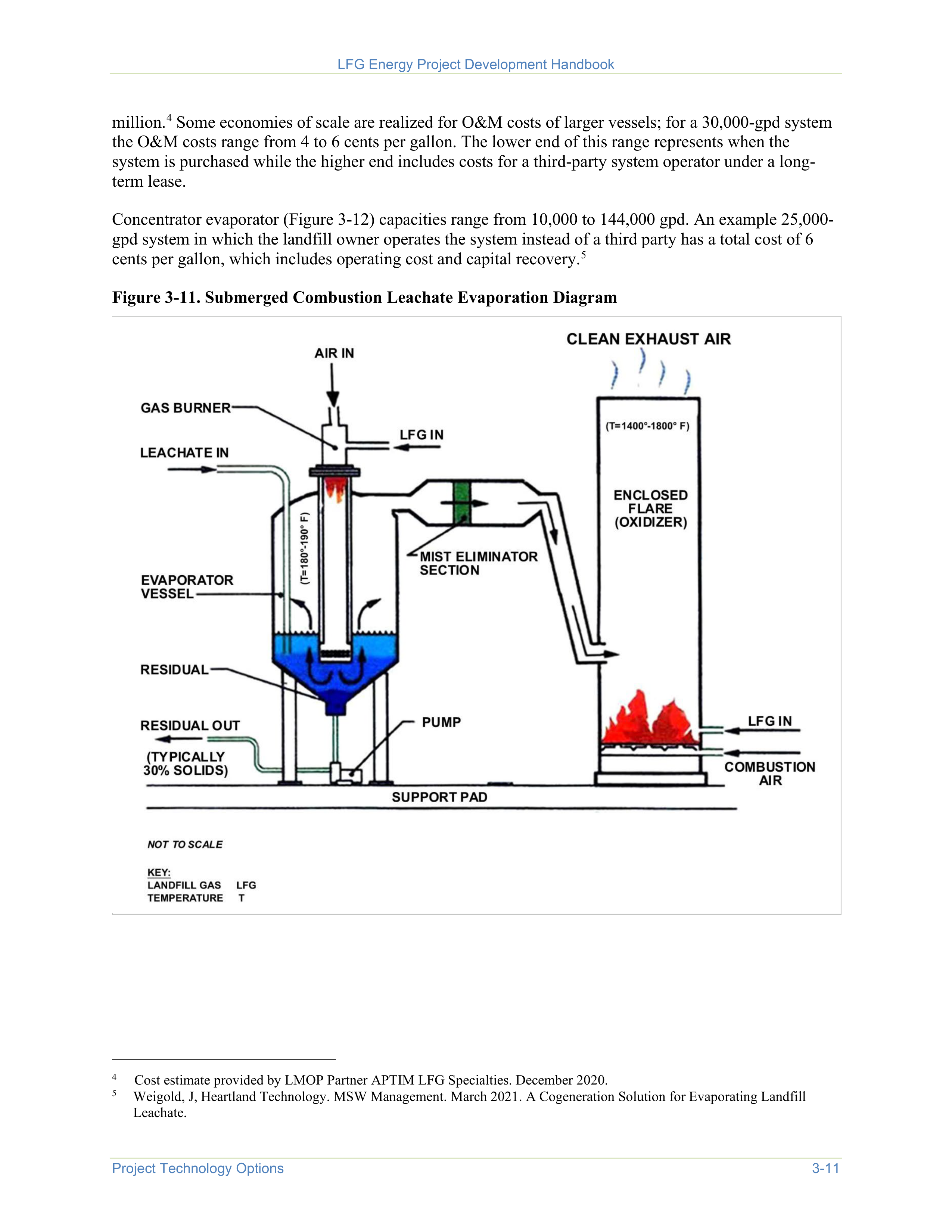
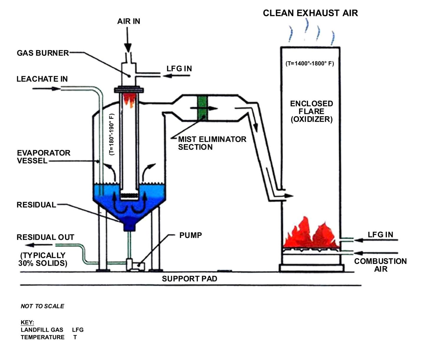
LFG Energy Project Development Handbook
Project Technology Options
3-11
million.
4
Some economies of scale are realized for O&M costs of larger vessels; for a 30,000-gpd system
the O&M costs range from 4 to 6 cents per gallon. The lower end of this range represents when the
system is purchased while the higher end includes costs for a third-party system operator under a long-
term lease.
4
Cost estimate provided by LMOP Partner APTIM LFG Specialties. December 2020.
Concentrator evaporator (Figure 3-12) capacities range from 10,000 to 144,000 gpd. An example 25,000-
gpd system in which the landfill owner operates the system instead of a third party has a total cost of 6
cents per gallon, which includes operating cost and capital recovery.
5
5
Weigold, J, Heartland Technology. MSW Management. March 2021. A Cogeneration Solution for Evaporating Landfill
Leachate.
Figure 3-11. Submerged Combustion Leachate Evaporation Diagram
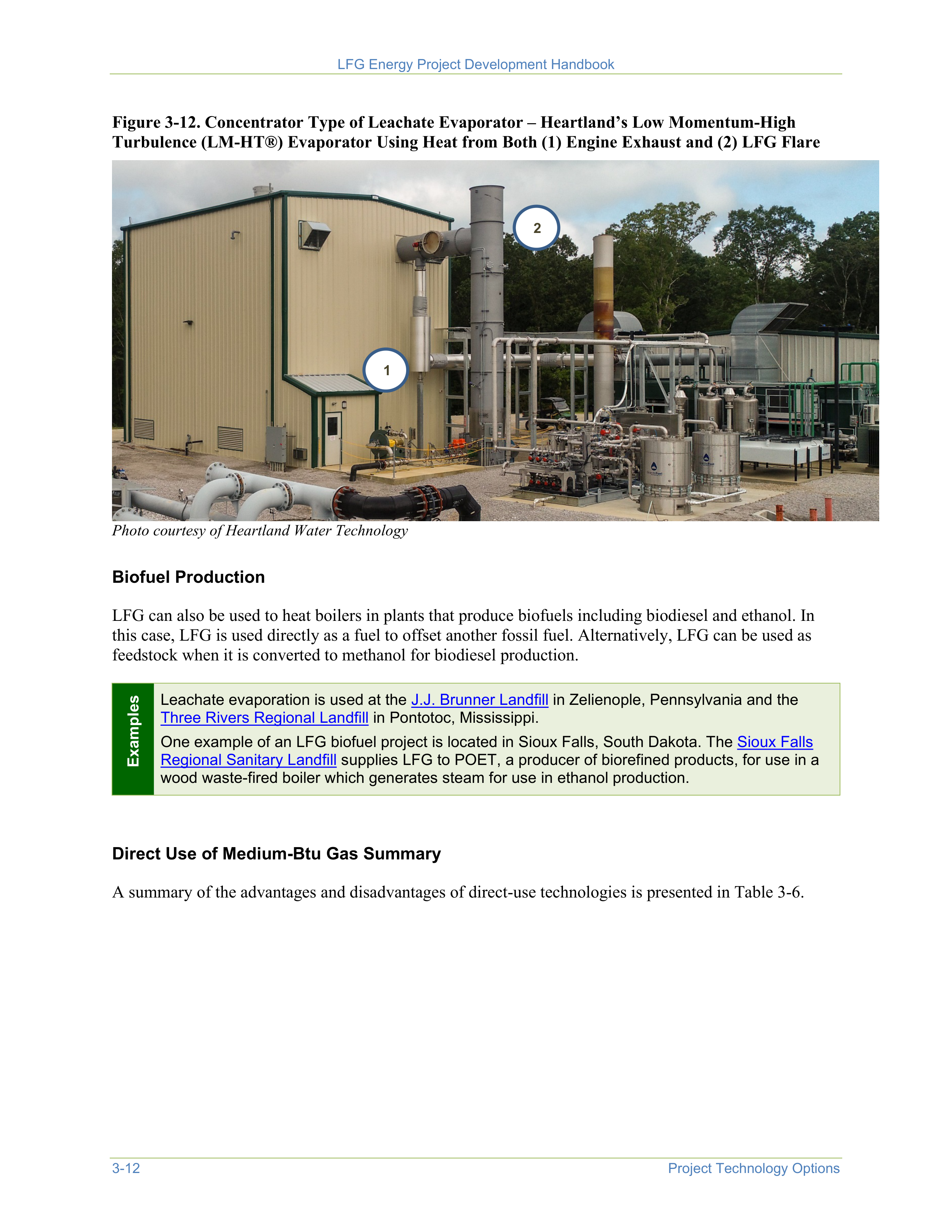
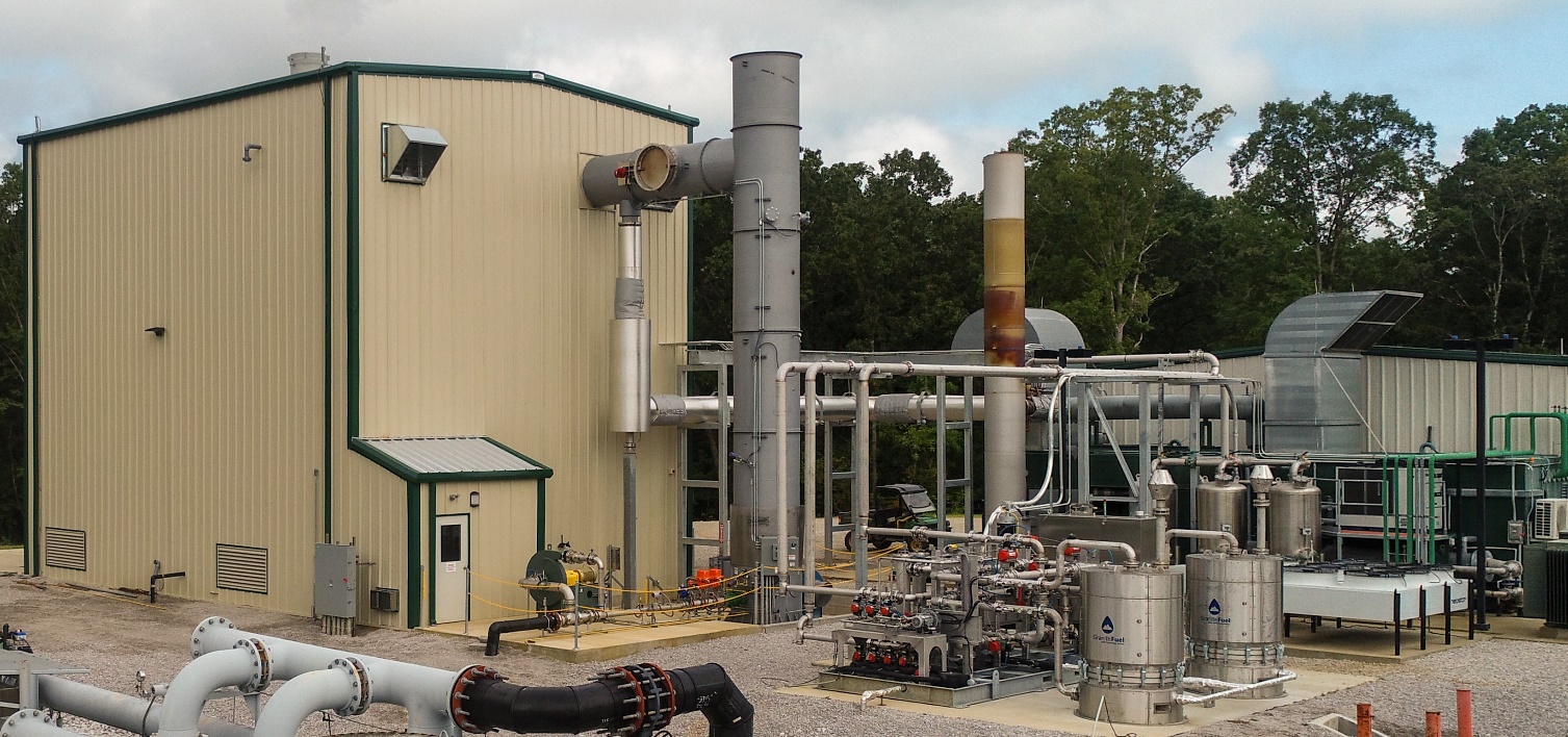


LFG Energy Project Development Handbook
3-12
Project Technology Options
Figure 3-12. Concentrator Type of Leachate Evaporator – Heartland’s Low Momentum-High
Turbulence (LM-HT®) Evaporator Using Heat from Both (1) Engine Exhaust and (2) LFG Flare
1
2
Photo courtesy of Heartland Water Technology
Biofuel Production
LFG can also be used to heat boilers in plants that produce biofuels including biodiesel and ethanol. In
this case, LFG is used directly as a fuel to offset another fossil fuel. Alternatively, LFG can be used as
feedstock when it is converted to methanol for biodiesel production.
Examples
Leachate evaporation is used at the
J.J. Brunner Landfill
in Zelienople, Pennsylvania and the
Three Rivers Regional Landfill
in Pontotoc, Mississippi.
One example of an LFG biofuel project is located in Sioux Falls, South Dakota. The
Sioux Falls
Regional Sanitary Landfill
supplies LFG to POET, a producer of biorefined products, for use in a
wood waste-fired boiler which generates steam for use in ethanol production.
Direct Use of Medium-Btu Gas Summary
A summary of the advantages and disadvantages of direct-use technologies is presented in Table 3-6.
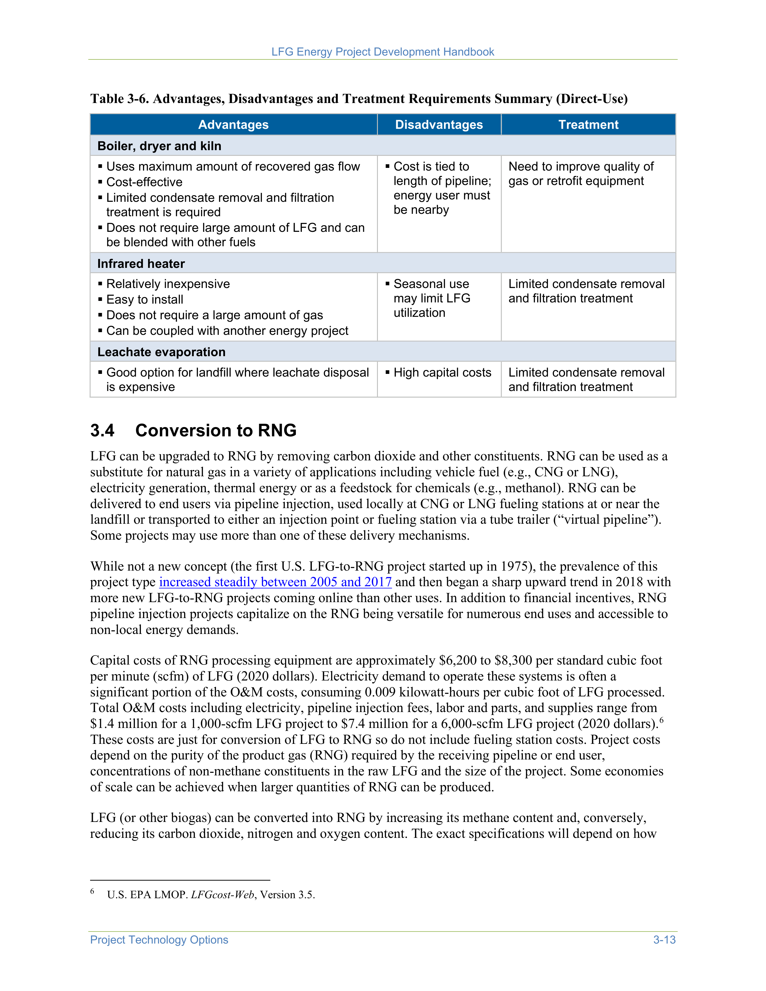
LFG Energy Project Development Handbook
Project Technology Options
3-13
Table 3-6. Advantages, Disadvantages and Treatment Requirements Summary (Direct-Use)
Advantages
Disadvantages
Treatment
Boiler, dryer and kiln
Uses maximum amount of recovered gas flow
Cost-effective
Limited condensate removal and filtration
treatment is required
Does not require large amount of LFG and can
be blended with other fuels
Cost is tied to
length of pipeline;
energy user must
be nearby
Need to improve quality of
gas or retrofit equipment
Infrared heater
Relatively inexpensive
Easy to install
Does not require a large amount of gas
Can be coupled with another energy project
Seasonal use
may limit LFG
utilization
Limited condensate removal
and filtration treatment
Leachate evaporation
Good option for landfill where leachate disposal
is expensive
High capital costs
Limited condensate removal
and filtration treatment
3.4
Conversion to RNG
LFG can be upgraded to RNG by removing carbon dioxide and other constituents. RNG can be used as a
substitute for natural gas in a variety of applications including vehicle fuel (e.g., CNG or LNG),
electricity generation, thermal energy or as a feedstock for chemicals (e.g., methanol). RNG can be
delivered to end users via pipeline injection, used locally at CNG or LNG fueling stations at or near the
landfill or transported to either an injection point or fueling station via a tube trailer (“virtual pipeline”).
Some projects may use more than one of these delivery mechanisms.
While not a new concept (the first U.S. LFG-to-RNG project started up in 1975), the prevalence of this
project type
increased steadily between 2005 and 2017
and then began a sharp upward trend in 2018 with
more new LFG-to-RNG projects coming online than other uses. In addition to financial incentives, RNG
pipeline injection projects capitalize on the RNG being versatile for numerous end uses and accessible to
non-local energy demands.
Capital costs of RNG processing equipment are approximately $6,200 to $8,300 per standard cubic foot
per minute (scfm) of LFG (2020 dollars). Electricity demand to operate these systems is often a
significant portion of the O&M costs, consuming 0.009 kilowatt-hours per cubic foot of LFG processed.
Total O&M costs including electricity, pipeline injection fees, labor and parts, and supplies range from
$1.4 million for a 1,000-scfm LFG project to $7.4 million for a 6,000-scfm LFG project (2020 dollars).
6
These costs are just for conversion of LFG to RNG so do not include fueling station costs. Project costs
depend on the purity of the product gas (RNG) required by the receiving pipeline or end user,
concentrations of non-methane constituents in the raw LFG and the size of the project. Some economies
of scale can be achieved when larger quantities of RNG can be produced.
LFG (or other biogas) can be converted into RNG by increasing its methane content and, conversely,
reducing its carbon dioxide, nitrogen and oxygen content. The exact specifications will depend on how
6
U.S. EPA LMOP.
LFGcost-Web
, Version 3.5.
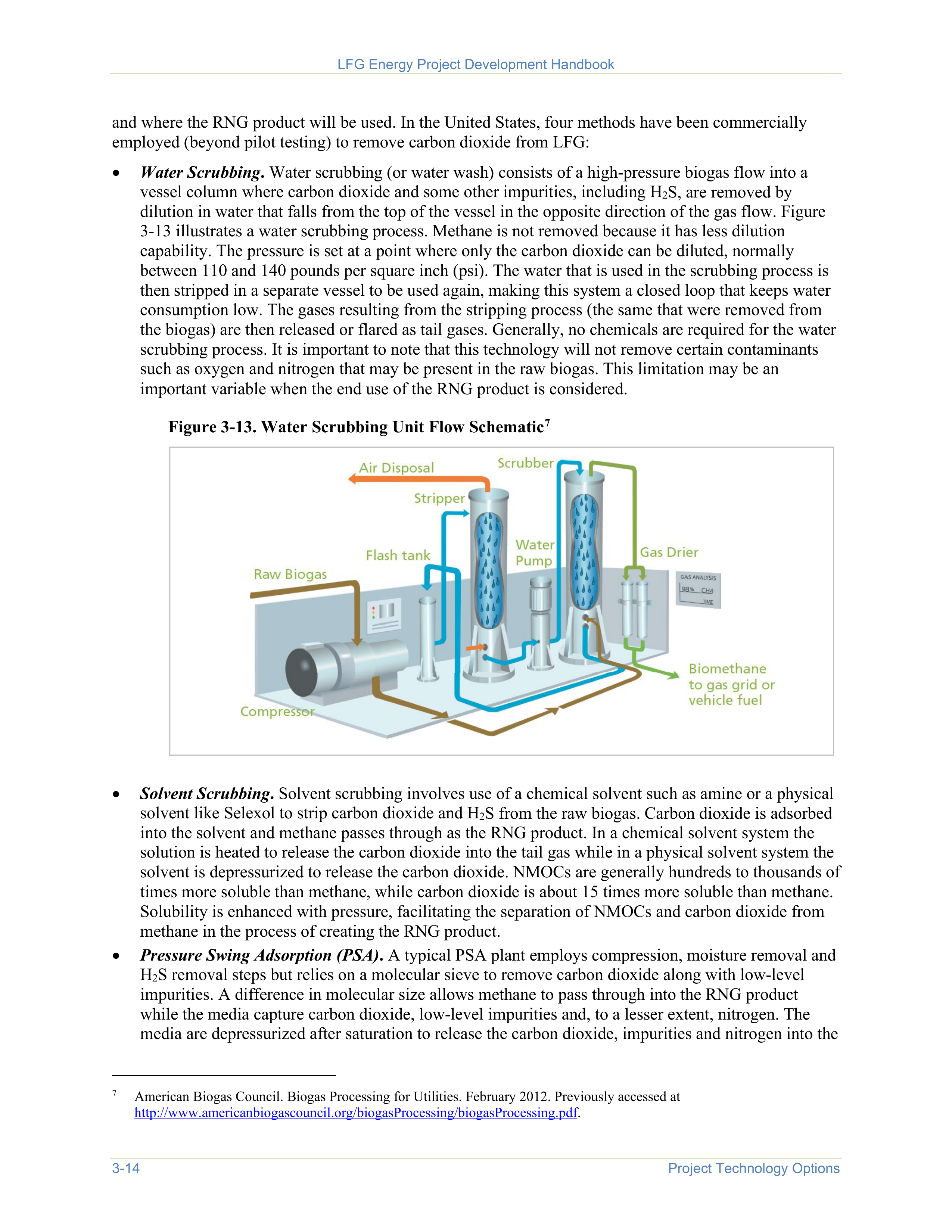
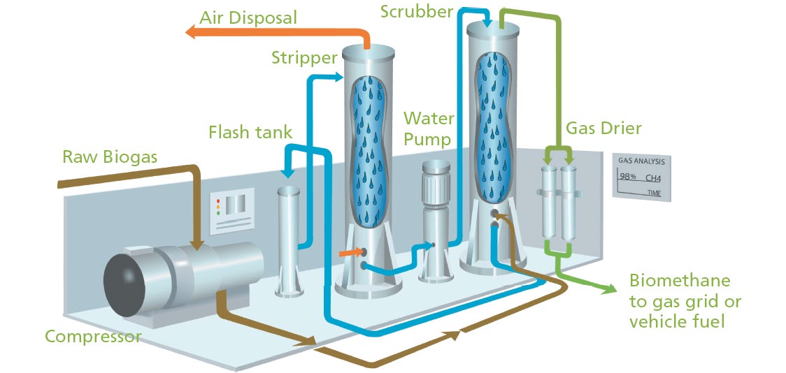
LFG Energy Project Development Handbook
3-14
Project Technology Options
and where the RNG product will be used. In the United States, four methods have been commercially
employed (beyond pilot testing) to remove carbon dioxide from LFG:
•
Water Scrubbing
.
Water scrubbing (or water wash) consists of a high-pressure biogas flow into a
vessel column where carbon dioxide and some other impurities, including H
2
S, are removed by
dilution in water that falls from the top of the vessel in the opposite direction of the gas flow. Figure
3-13 illustrates a water scrubbing process. Methane is not removed because it has less dilution
capability. The pressure is set at a point where only the carbon dioxide can be diluted, normally
between 110 and 140 pounds per square inch (psi). The water that is used in the scrubbing process is
then stripped in a separate vessel to be used again, making this system a closed loop that keeps water
consumption low. The gases resulting from the stripping process (the same that were removed from
the biogas) are then released or flared as tail gases. Generally, no chemicals are required for the water
scrubbing process. It is important to note that this technology will not remove certain contaminants
such as oxygen and nitrogen that may be present in the raw biogas. This limitation may be an
important variable when the end use of the RNG product is considered.
Figure 3-13. Water Scrubbing Unit Flow Schematic
7
•
Solvent Scrubbing
.
Solvent scrubbing involves use of a chemical solvent such as amine or a physical
solvent like Selexol to strip carbon dioxide and H
2
S from the raw biogas. Carbon dioxide is adsorbed
into the solvent and methane passes through as the RNG product. In a chemical solvent system the
solution is heated to release the carbon dioxide into the tail gas while in a physical solvent system the
solvent is depressurized to release the carbon dioxide. NMOCs are generally hundreds to thousands of
times more soluble than methane, while carbon dioxide is about 15 times more soluble than methane.
Solubility is enhanced with pressure, facilitating the separation of NMOCs and carbon dioxide from
methane in the process of creating the RNG product.
•
Pressure Swing Adsorption (PSA)
.
A typical PSA plant employs compression, moisture removal and
H
2
S removal steps but relies on a molecular sieve to remove carbon dioxide along with low-level
impurities. A difference in molecular size allows methane to pass through into the RNG product
while the media capture carbon dioxide, low-level impurities and, to a lesser extent, nitrogen. The
media are depressurized after saturation to release the carbon dioxide, impurities and nitrogen into the
7
American Biogas Council. Biogas Processing for Utilities. February 2012. Previously accessed at
http://www.americanbiogascouncil.org/biogasProcessing/biogasProcessing.pdf
.
LFG Energy Project Development Handbook
Project Technology Options
3-15
tail gas. Once exhausted, the media can be regenerated through a depressurizing and purge cycle.
PSA is also known as a molecular sieve process.
•
Membrane Systems
.
A typical membrane plant employs compression, moisture removal and H
2
S
removal steps but relies on activated carbon or PSA to remove NMOCs and membranes to remove
carbon dioxide. Removing the NMOCs protects the membranes. The membrane process takes
advantage of the physical property that gases, under the same conditions, will pass through polymeric
membranes at differing rates. Carbon dioxide passes through the membrane approximately 20 times
faster than methane. Differential pressure across the membrane wall is the driving force for the
separation process. Project-specific RNG quality specifications and project size will help determine if
a single-pass or multiple-pass membrane system is needed.
In addition to carbon dioxide removal, many RNG projects employ treatment technologies to reduce
nitrogen, oxygen and other LFG constituents. Air intrusion is the primary cause for the presence of
oxygen and nitrogen in LFG and can occur when air is drawn through the surface of the landfill and into
the GCS due to the vacuum on the wellfield. Air intrusion can often be minimized by adjusting well
vacuums and repairing leaks in the landfill cover. In some instances, air intrusion can be managed by
sending LFG from the interior wells directly to the RNG production process and sending LFG from the
perimeter wells (which often have higher nitrogen and oxygen levels) to another beneficial use or
emissions control device. Adjusting the GCS to achieve a desired nitrogen level may impact the amount
of LFG available — LMOP’s
RNG Flow Rate Estimation Tool
can serve as a screening tool to help
estimate normalized gas flows for RNG projects.
Nitrogen remaining in the intermediate gas stream, following any wellfield adjustments and initial
treatment to remove carbon dioxide and possibly other constituents, can be removed using PSA,
membrane or cryogenic distillation technologies. At least two types of PSA – an activated carbon
adsorbent type (also removes oxygen) and a kinetic type – are available for nitrogen removal. A multi-
stage membrane process is also available for nitrogen removal using a polyether ether ketone membrane
material which preferentially separates methane from nitrogen as compared to the polyimide material
used for carbon dioxide removal. Low-pressure cryogenic distillation separates methane from air gases by
lowering the temperature of the gas stream to a point where the methane liquefies but nitrogen and
oxygen do not.
Treatment technologies (PSA, membrane) used for removal of carbon dioxide or nitrogen can also
achieve varying levels of oxygen removal. In addition, there is a stand-alone option for oxygen removal
using a catalytic reactor process wherein the oxygen reacts with methane to produce carbon dioxide and
water.
LMOP’s
An Overview of Renewable Natural Gas from Biogas
document provides more details about
purification processes and technologies, as well as additional information about RNG project
development. LMOP’s
Renewable Natural Gas webpage
also provides information and resources for this
project type.
Examples
In Rochester, New Hampshire, LFG from the
Turnkey Recycling and Environmental Enterprises
(TREE) Landfill
is processed into RNG and then piped 12.7 miles to the University of New
Hampshire for combustion in the campus’ gas turbine CHP plant.
RNG produced at the
Seabreeze Environmental Landfill
in Angleton, Texas is provided to OCI
NV in Beaumont, Texas in a “directed biogas” project, wherein the end user extracts an amount
of natural gas from the pipeline that is equivalent to the amount of RNG injected into the
pipeline by the project. The OCI NV methanol plant is about 100 miles away from the landfill.
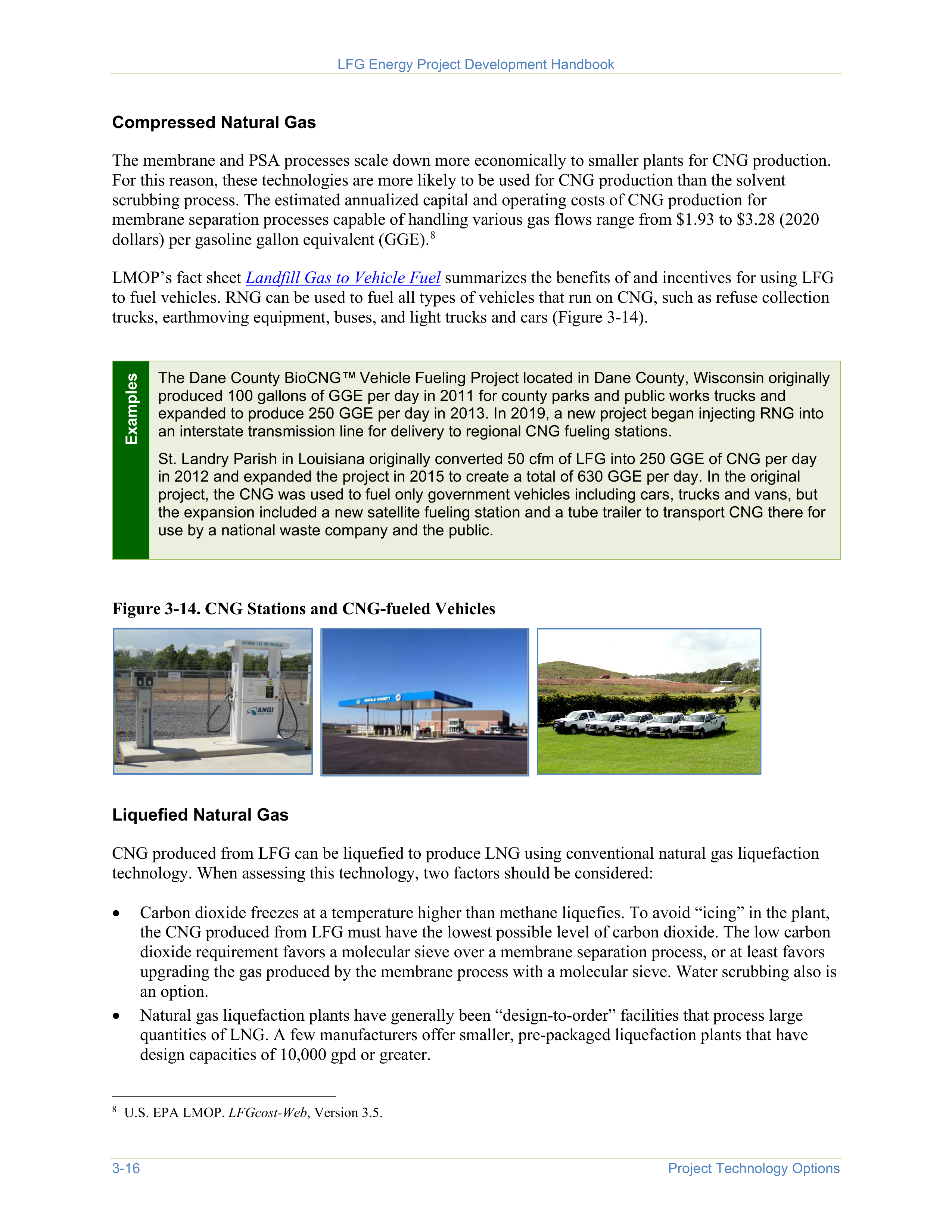
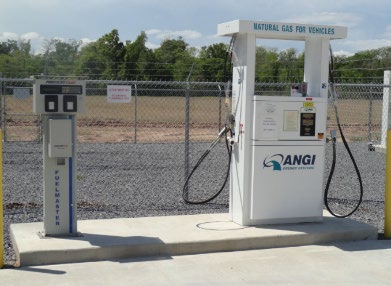
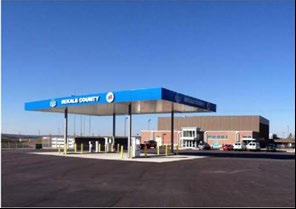
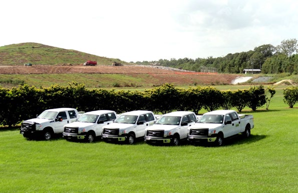
LFG Energy Project Development Handbook
3-16
Project Technology Options
Compressed Natural Gas
The membrane and PSA processes scale down more economically to smaller plants for CNG production.
For this reason, these technologies are more likely to be used for CNG production than the solvent
scrubbing process. The estimated annualized capital and operating costs of CNG production for
membrane separation processes capable of handling various gas flows range from $1.93 to $3.28 (2020
dollars) per gasoline gallon equivalent (GGE).
8
8
U.S. EPA LMOP.
LFGcost-Web
, Version 3.5.
LMOP’s fact sheet
Landfill Gas to Vehicle Fuel
summarizes the benefits of and incentives for using LFG
to fuel vehicles. RNG can be used to fuel all types of vehicles that run on CNG, such as refuse collection
trucks, earthmoving equipment, buses, and light trucks and cars (Figure 3-14).
Examples
The Dane County BioCNG™
Vehicle Fueling Project located in Dane County, Wisconsin originally
produced 100 gallons of GGE per day in 2011 for county parks and public works trucks and
expanded to produce 250 GGE per day in 2013. In 2019, a new project began injecting RNG into
an interstate transmission line for delivery to regional CNG fueling stations.
St. Landry Parish in Louisiana originally converted 50 cfm of LFG into 250 GGE of CNG per day
in 2012 and expanded the project in 2015 to create a total of 630 GGE per day. In the original
project, the CNG was used to fuel only government vehicles including cars, trucks and vans, but
the expansion included a new satellite fueling station and a tube trailer to transport CNG there for
use by a national waste company and the public.
Figure 3-14. CNG Stations and CNG-fueled Vehicles
Liquefied Natural Gas
CNG produced from LFG can be liquefied to produce LNG using conventional natural gas liquefaction
technology. When assessing this technology, two factors should be considered:
•
Carbon dioxide freezes at a temperature higher than methane liquefies. To avoid “icing” in the plant,
the CNG produced from LFG must have the lowest possible level of carbon dioxide. The low carbon
dioxide requirement favors a molecular sieve over a membrane separation process, or at least favors
upgrading the gas produced by the membrane process with a molecular sieve. Water scrubbing also is
an option.
•
Natural gas liquefaction plants have generally been “design-to-order” facilities that process large
quantities of LNG. A few manufacturers offer smaller, pre-packaged liquefaction plants that have
design capacities of 10,000 gpd or greater.
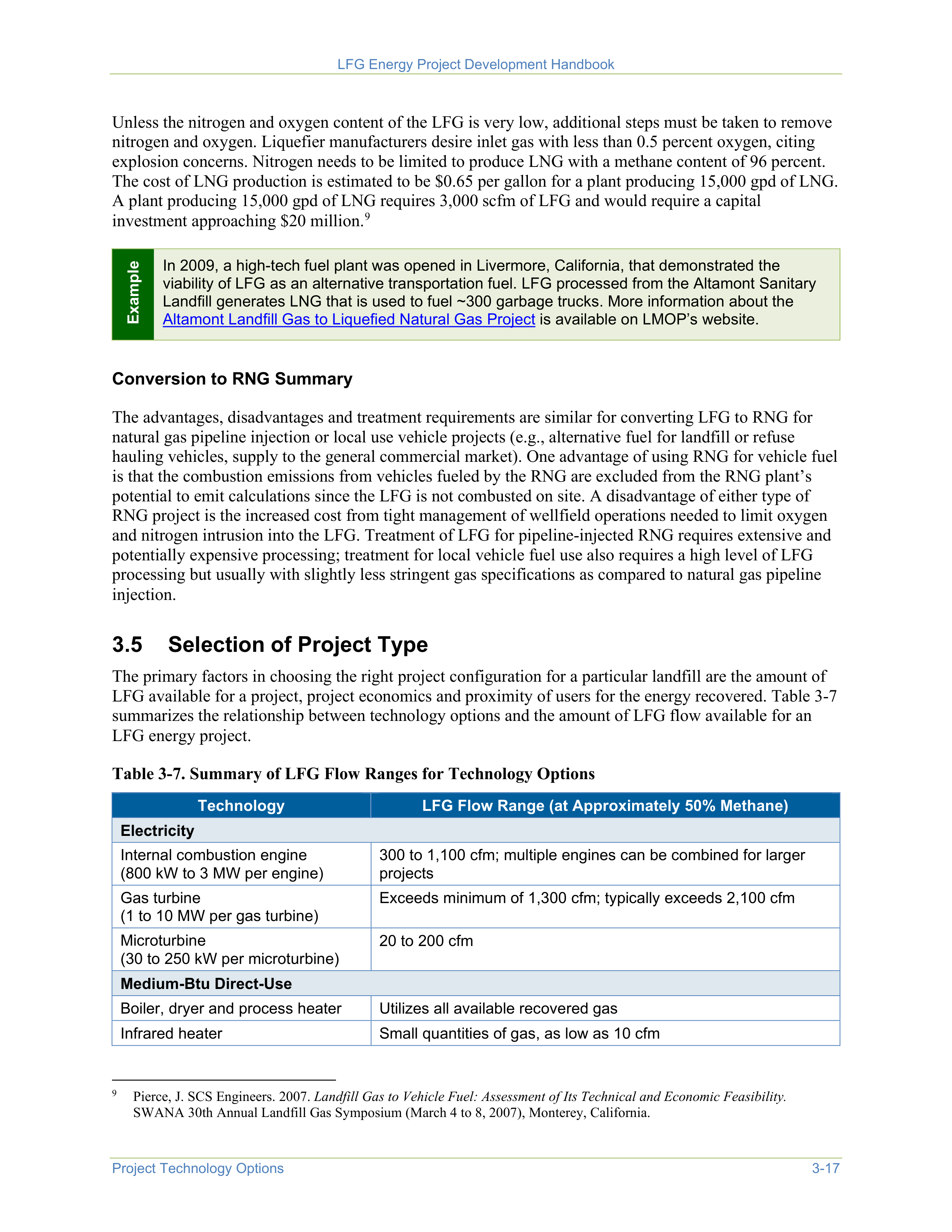
LFG Energy Project Development Handbook
Project Technology Options
3-17
Unless the nitrogen and oxygen content of the LFG is very low, additional steps must be taken to remove
nitrogen and oxygen. Liquefier manufacturers desire inlet gas with less than 0.5 percent oxygen, citing
explosion concerns. Nitrogen needs to be limited to produce LNG with a methane content of 96 percent.
The cost of LNG production is estimated to be $0.65 per gallon for a plant producing 15,000 gpd of LNG.
A plant producing 15,000 gpd of LNG requires 3,000 scfm of LFG and would require a capital
investment approaching $20 million.
9
9
Pierce, J. SCS Engineers. 2007.
Landfill Gas to Vehicle Fuel: Assessment of Its Technical and Economic Feasibility.
SWANA 30th Annual Landfill Gas Symposium (March 4 to 8, 2007), Monterey, California.
Example
In 2009, a high-tech fuel plant was opened in Livermore, California, that demonstrated the
viability of LFG as an alternative transportation fuel. LFG processed from the Altamont Sanitary
Landfill generates LNG that is used to fuel ~300 garbage trucks. More information about the
Altamont Landfill Gas to Liquefied Natural Gas Project
is available on LMOP’s website.
Conversion to RNG Summary
The advantages, disadvantages and treatment requirements are similar for converting LFG to RNG for
natural gas pipeline injection or local use vehicle projects (e.g., alternative fuel for landfill or refuse
hauling vehicles, supply to the general commercial market). One advantage of using RNG for vehicle fuel
is that the combustion emissions from vehicles fueled by the RNG are excluded from the RNG plant’s
potential to emit calculations since the LFG is not combusted on site. A disadvantage of either type of
RNG project is the increased cost from tight management of wellfield operations needed to limit oxygen
and nitrogen intrusion into the LFG. Treatment of LFG for pipeline-injected RNG requires extensive and
potentially expensive processing; treatment for local vehicle fuel use also requires a high level of LFG
processing but usually with slightly less stringent gas specifications as compared to natural gas pipeline
injection.
3.5
Selection of Project Type
The primary factors in choosing the right project configuration for a particular landfill are the amount of
LFG available for a project, project economics and proximity of users for the energy recovered. Table 3-7
summarizes the relationship between technology options and the amount of LFG flow available for an
LFG energy project.
Table 3-7. Summary of LFG Flow Ranges for Technology Options
Technology
LFG Flow Range (at Approximately 50% Methane)
Electricity
Internal combustion engine
(800 kW to 3 MW per engine)
300 to 1,100 cfm; multiple engines can be combined for larger
projects
Gas turbine
(1 to 10 MW per gas turbine)
Exceeds minimum of 1,300 cfm; typically exceeds 2,100 cfm
Microturbine
(30 to 250 kW per microturbine)
20 to 200 cfm
Medium-Btu Direct-Use
Boiler, dryer and process heater
Utilizes all available recovered gas
Infrared heater
Small quantities of gas, as low as 10 cfm
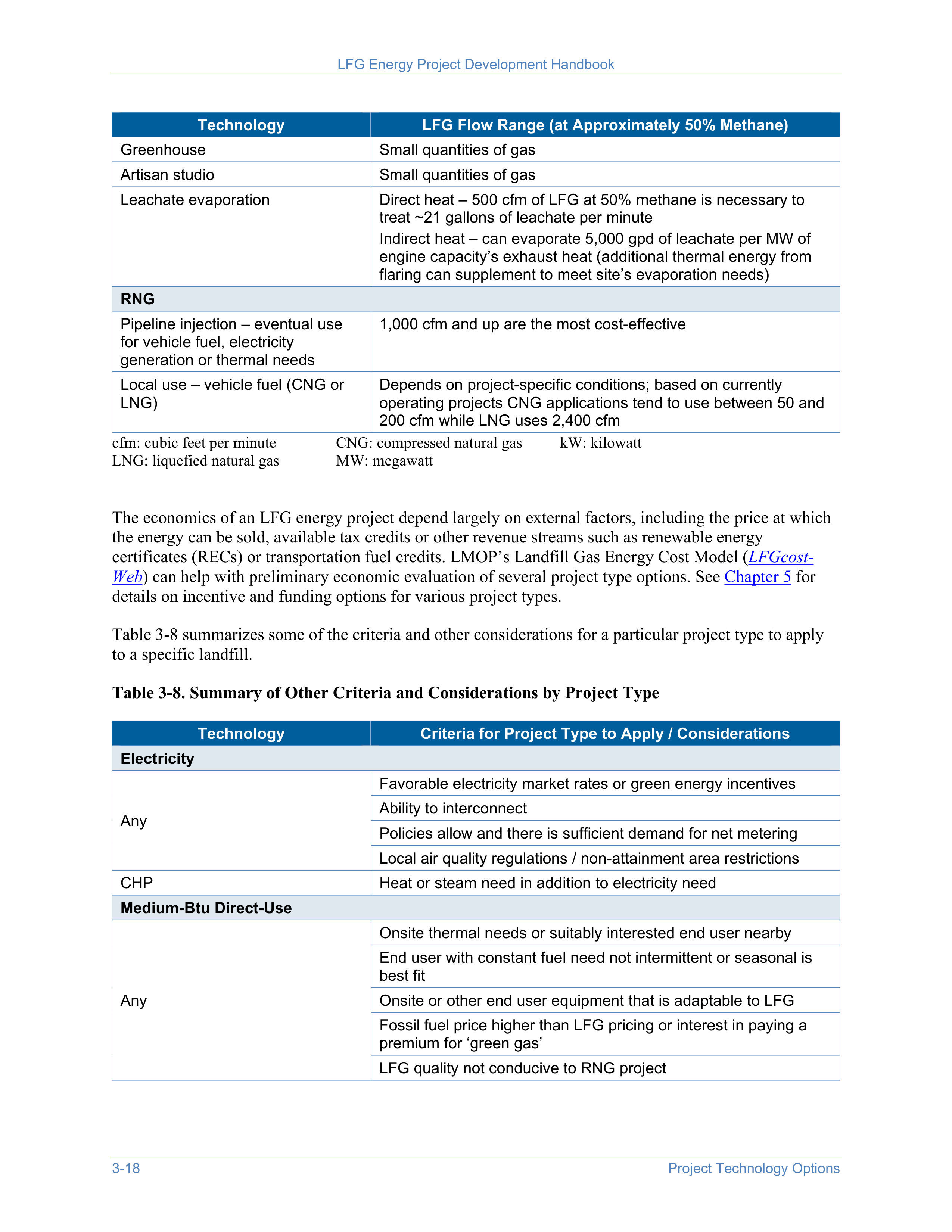
LFG Energy Project Development Handbook
3-18
Project Technology Options
Technology
LFG Flow Range (at Approximately 50% Methane)
Greenhouse
Small quantities of gas
Artisan studio
Small quantities of gas
Leachate evaporation
Direct heat – 500 cfm of LFG at 50% methane is necessary to
treat ~21 gallons of leachate per minute
Indirect heat – can evaporate 5,000 gpd of leachate per MW of
engine capacity’s exhaust heat (additional thermal energy from
flaring can supplement to meet site’s evaporation needs)
RNG
Pipeline injection – eventual use
for vehicle fuel, electricity
generation or thermal needs
1,000 cfm and up are the most cost-effective
Local use – vehicle fuel (CNG or
LNG)
Depends on project-specific conditions; based on currently
operating projects CNG applications tend to use between 50 and
200 cfm while LNG uses 2,400 cfm
cfm: cubic feet per minute
CNG: compressed natural gas
kW: kilowatt
LNG: liquefied natural gas
MW: megawatt
The economics of an LFG energy project depend largely on external factors, including the price at which
the energy can be sold, available tax credits or other revenue streams such as renewable energy
certificates (RECs) or transportation fuel credits. LMOP’s Landfill Gas Energy Cost Model (
LFGcost-
Web
) can help with preliminary economic evaluation of several project type options. See
Chapter 5
for
details on incentive and funding options for various project types.
Table 3-8 summarizes some of the criteria and other considerations for a particular project type to apply
to a specific landfill.
Table 3-8. Summary of Other Criteria and Considerations by Project Type
Technology
Criteria for Project Type to Apply / Considerations
Electricity
Any
Favorable electricity market rates or green energy incentives
Ability to interconnect
Policies allow and there is sufficient demand for net metering
Local air quality regulations / non-attainment area restrictions
CHP
Heat or steam need in addition to electricity need
Medium-Btu Direct-Use
Any
Onsite thermal needs or suitably interested end user nearby
End user with constant fuel need not intermittent or seasonal is
best fit
Onsite or other end user equipment that is adaptable to LFG
Fossil fuel price higher than LFG pricing or interest in paying a
premium for ‘green gas’
LFG quality not conducive to RNG project
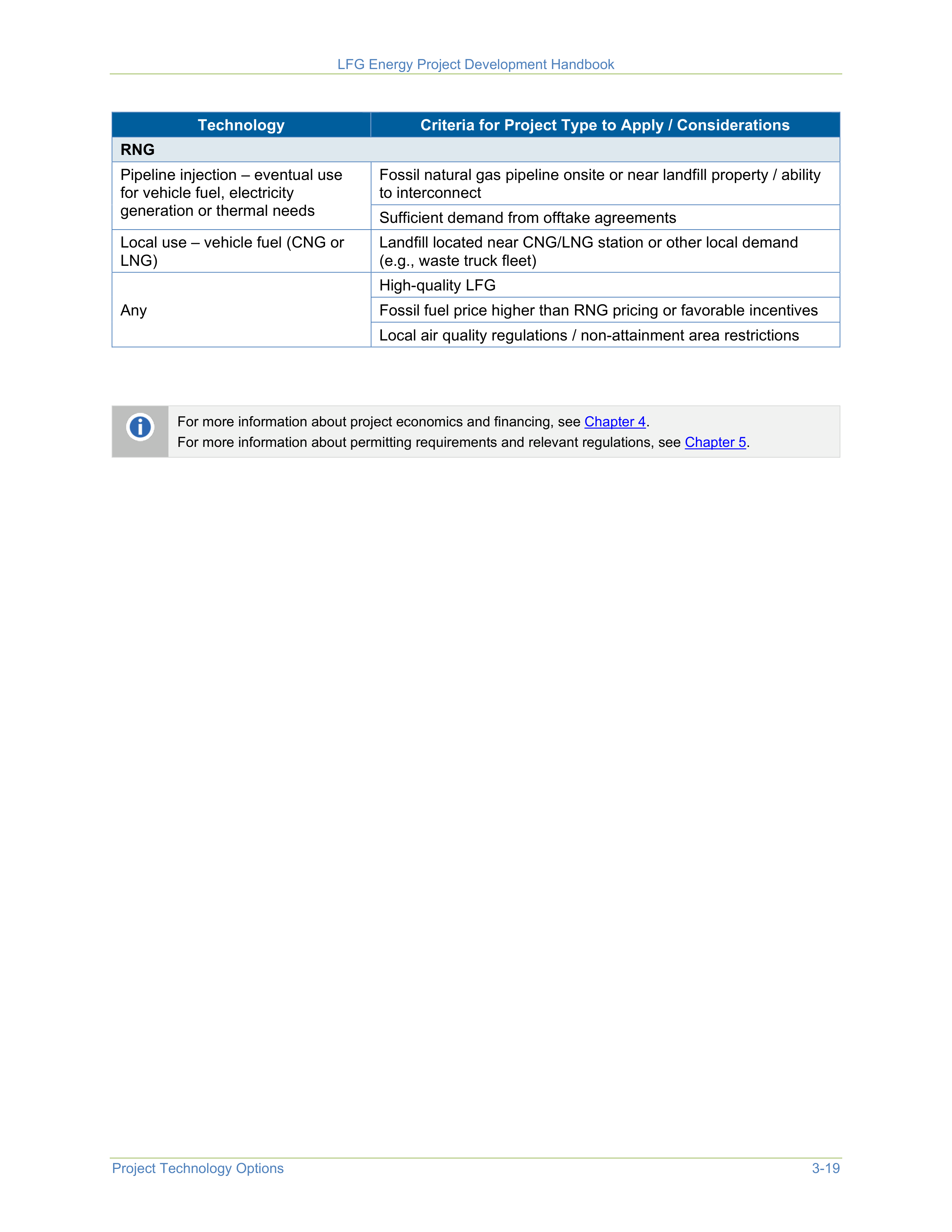

LFG Energy Project Development Handbook
Project Technology Options
3-19
Technology
Criteria for Project Type to Apply / Considerations
RNG
Pipeline injection – eventual use
for vehicle fuel, electricity
generation or thermal needs
Fossil natural gas pipeline onsite or near landfill property / ability
to interconnect
Sufficient demand from offtake agreements
Local use – vehicle fuel (CNG or
LNG)
Landfill located near CNG/LNG station or other local demand
(e.g., waste truck fleet)
Any
High-quality LFG
Fossil fuel price higher than RNG pricing or favorable incentives
Local air quality regulations / non-attainment area restrictions
For more information about project economics and financing, see
Chapter 4
.
For more information about permitting requirements and relevant regulations, see
Chapter 5
.

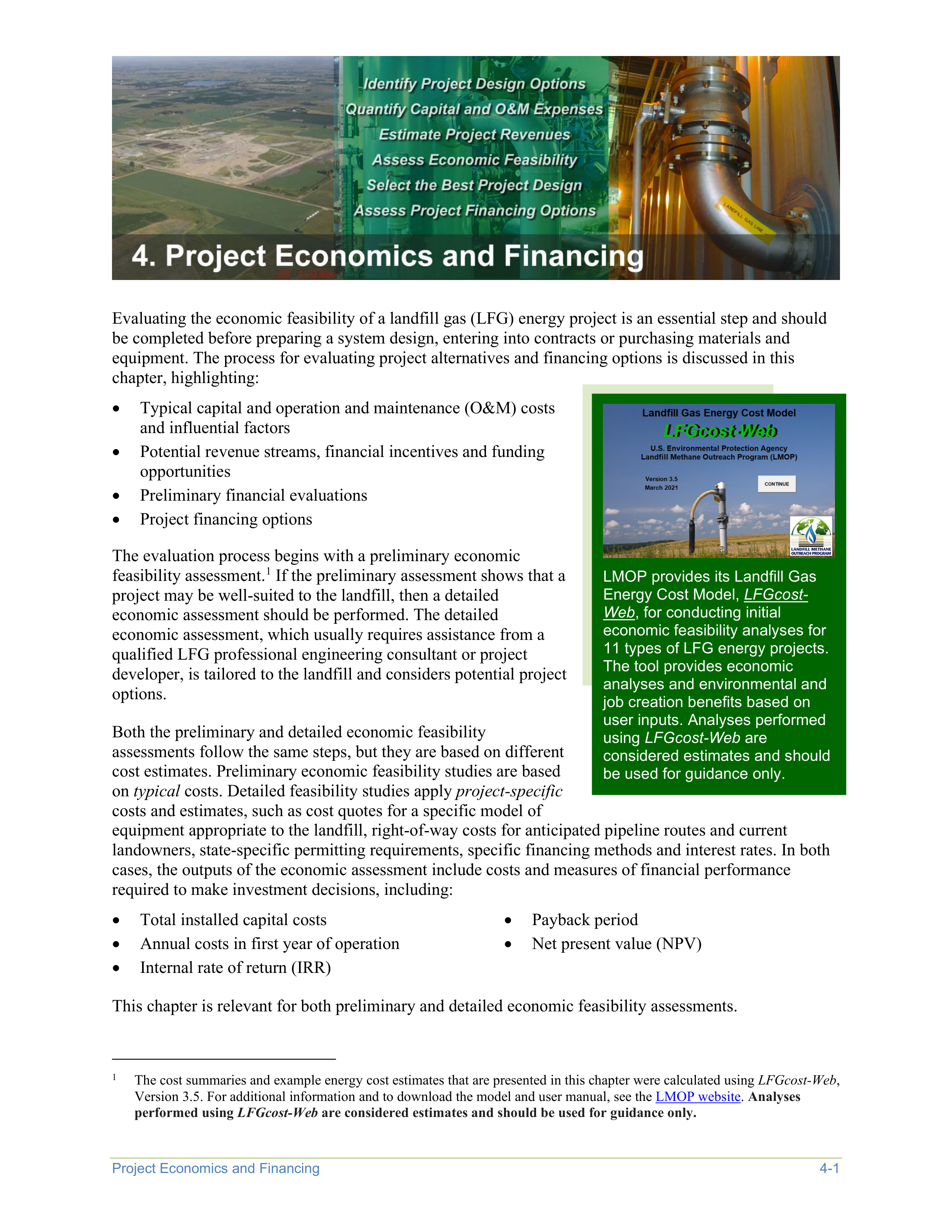


Project Economics and Financing
4-1
Evaluating the economic feasibility of a landfill gas (LFG) energy project is an essential step and should
be completed before preparing a system design, entering into contracts or purchasing materials and
equipment. The process for evaluating project alternatives and financing options is discussed in this
chapter, highlighting:
•
Typical capital and operation and maintenance (O&M) costs
and influential factors
•
Potential revenue streams, financial incentives and funding
opportunities
•
Preliminary financial evaluations
•
Project financing options
LMOP provides its Landfill Gas
Energy Cost Model,
LFGcost-
Web
, for conducting initial
economic feasibility analyses for
11 types of LFG energy projects.
The tool provides economic
analyses and environmental and
job creation benefits based on
user inputs. Analyses performed
using
LFGcost-Web
are
considered estimates and should
be used for guidance only.
The evaluation process begins with a preliminary economic
feasibility assessment.
1
If the preliminary assessment shows that a
project may be well-suited to the landfill, then a detailed
economic assessment should be performed. The detailed
economic assessment, which usually requires assistance from a
qualified LFG professional engineering consultant or project
developer, is tailored to the landfill and considers potential project
options.
1
The cost summaries and example energy cost estimates that are presented in this chapter were calculated using
LFGcost-Web
,
Version 3.5. For additional information and to download the model and user manual, see the
LMOP website
.
Analyses
performed using
LFGcost-Web
are considered estimates and should be used for guidance only.
Both the preliminary and detailed economic feasibility
assessments follow the same steps, but they are based on different
cost estimates. Preliminary economic feasibility studies are based
on
typical
costs. Detailed feasibility studies apply
project-specific
costs and estimates, such as cost quotes for a specific model of
equipment appropriate to the landfill, right-of-way costs for anticipated pipeline routes and current
landowners, state-specific permitting requirements, specific financing methods and interest rates. In both
cases, the outputs of the economic assessment include costs and measures of financial performance
required to make investment decisions, including:
•
Total installed capital costs
•
Annual costs in first year of operation
•
Internal rate of return (IRR)
•
Payback period
•
Net present value (NPV)
This chapter is relevant for both preliminary and detailed economic feasibility assessments.
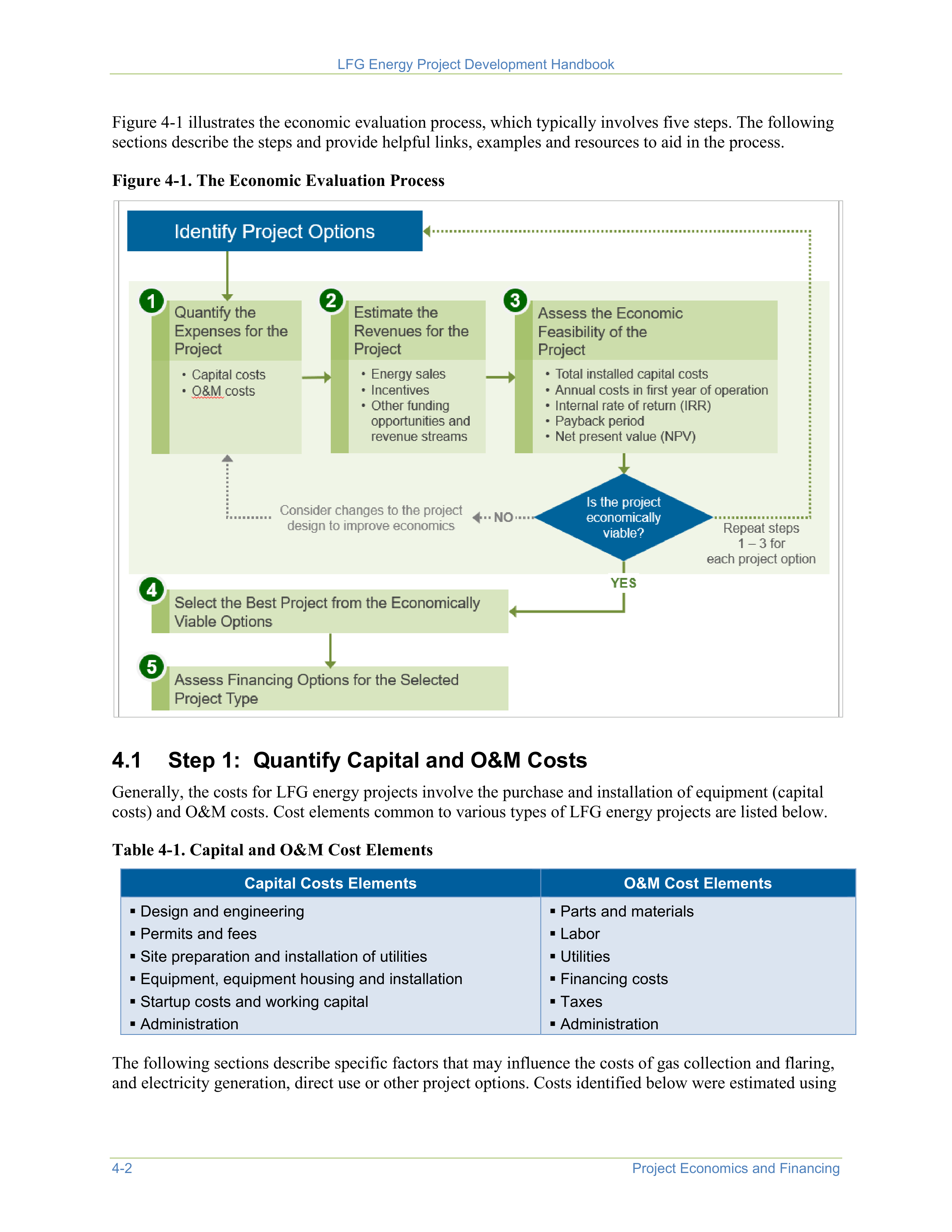
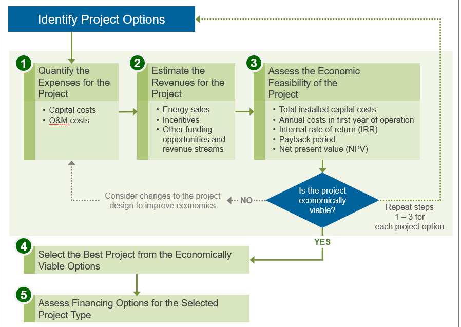
LFG Energy Project Development Handbook
4-2
Project Economics and Financing
Figure 4-1 illustrates the economic evaluation process, which typically involves five steps. The following
sections describe the steps and provide helpful links, examples and resources to aid in the process.
Figure 4-1. The Economic Evaluation Process
4.1 Step 1: Quantify Capital and O&M Costs
Generally, the costs for LFG energy projects involve the purchase and installation of equipment (capital
costs) and O&M costs. Cost elements common to various types of LFG energy projects are listed below.
Table 4-1. Capital and O&M Cost Elements
Capital Costs Elements
O&M Cost Elements
Design and engineering
Permits and fees
Site preparation and installation of utilities
Equipment, equipment housing and installation
Startup costs and working capital
Administration
Parts and materials
Labor
Utilities
Financing costs
Taxes
Administration
The following sections describe specific factors that may influence the costs of gas collection and flaring,
and electricity generation, direct use or other project options. Costs identified below were estimated using
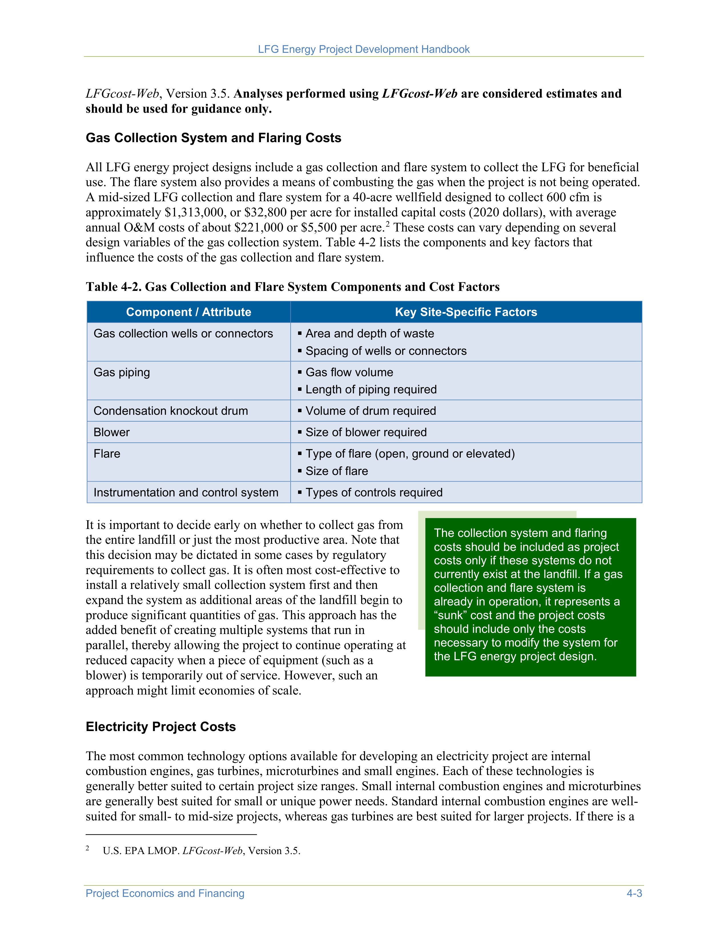


LFG Energy Project Development Handbook
Project Economics and Financing
4-3
LFGcost-Web
, Version 3.5.
Analyses performed using
LFGcost-Web
are considered estimates and
should be used for guidance only.
Gas Collection System and Flaring Costs
All LFG energy project designs include a gas collection and flare system to collect the LFG for beneficial
use. The flare system also provides a means of combusting the gas when the project is not being operated.
A mid-sized LFG collection and flare system for a 40-acre wellfield designed to collect 600 cfm is
approximately $1,313,000, or $32,800 per acre for installed capital costs (2020 dollars), with average
annual O&M costs of about $221,000 or $5,500 per acre.
2
These costs can vary depending on several
design variables of the gas collection system. Table 4-2 lists the components and key factors that
influence the costs of the gas collection and flare system.
2
U.S. EPA LMOP.
LFGcost-Web
, Version 3.5.
Table 4-2. Gas Collection and Flare System Components and Cost Factors
Component / Attribute
Key Site-Specific Factors
Gas collection wells or connectors
Area and depth of waste
Spacing of wells or connectors
Gas piping
Gas flow volume
Length of piping required
Condensation knockout drum
Volume of drum required
Blower
Size of blower required
Flare
Type of flare (open, ground or elevated)
Size of flare
Instrumentation and control system
Types of controls required
It is important to decide early on whether to collect gas from
the entire landfill or just the most productive area. Note that
this decision may be dictated in some cases by regulatory
requirements to collect gas. It is often most cost-effective to
install a relatively small collection system first and then
expand the system as additional areas of the landfill begin to
produce significant quantities of gas. This approach has the
added benefit of creating multiple systems that run in
parallel, thereby allowing the project to continue operating at
reduced capacity when a piece of equipment (such as a
blower) is temporarily out of service. However, such an
approach might limit economies of scale.
The collection system and flaring
costs should be included as project
costs only if these systems do not
currently exist at the landfill. If a gas
collection and flare system is
already in operation, it represents a
“sunk” cost and the project costs
should include only the costs
necessary to modify the system for
the LFG energy project design.
Electricity Project Costs
The most common technology options available for developing an electricity project are internal
combustion engines, gas turbines, microturbines and small engines. Each of these technologies is
generally better suited to certain project size ranges. Small internal combustion engines and microturbines
are generally best suited for small or unique power needs. Standard internal combustion engines are well-
suited for small- to mid-size projects, whereas gas turbines are best suited for larger projects. If there is a
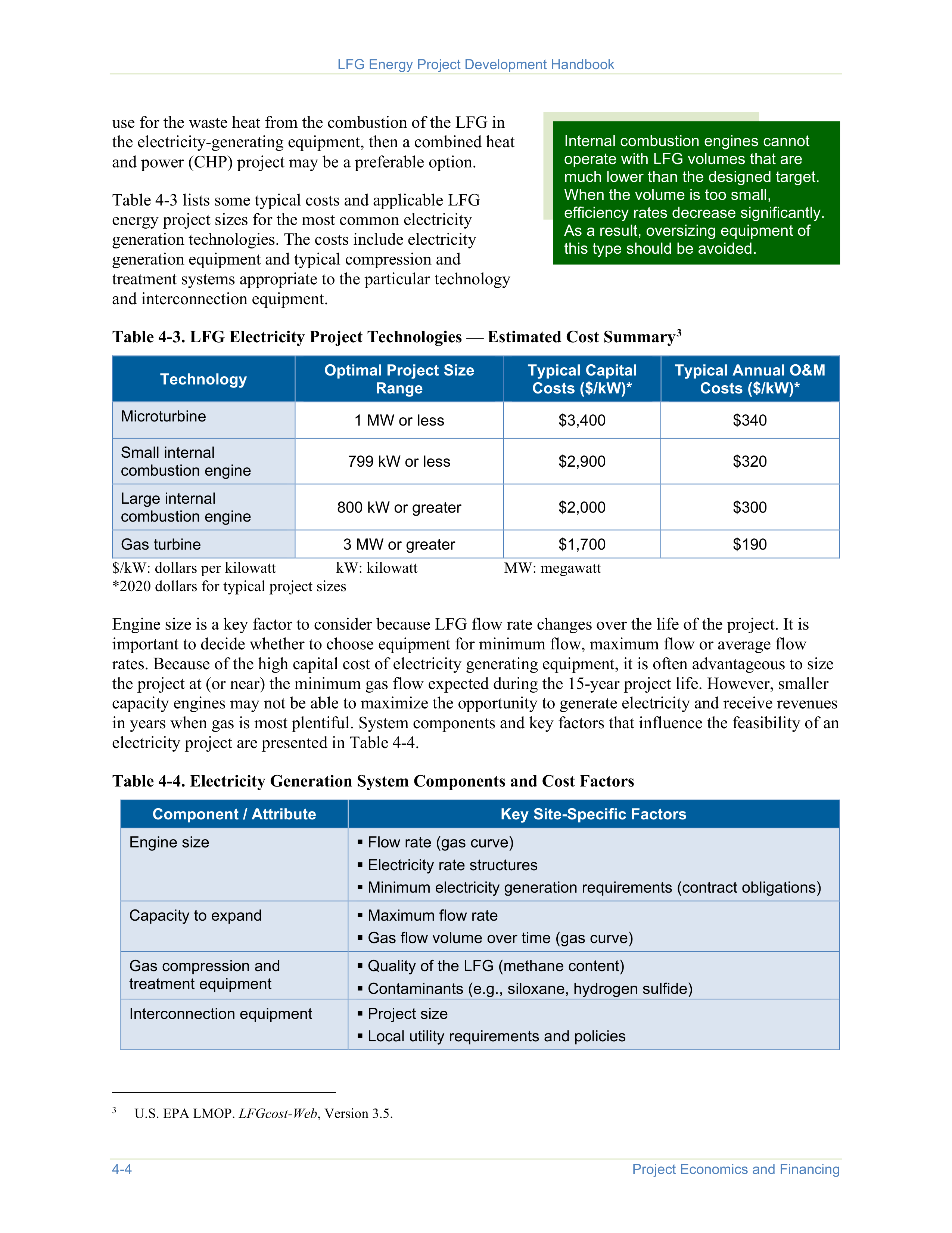


LFG Energy Project Development Handbook
4-4
Project Economics and Financing
use for the waste heat from the combustion of the LFG in
the electricity-generating equipment, then a combined heat
and power (CHP) project may be a preferable option.
Table 4-3 lists some typical costs and applicable LFG
energy project sizes for the most common electricity
generation technologies. The costs include electricity
generation equipment and typical compression and
treatment systems appropriate to the particular technology
and interconnection equipment.
Internal combustion engines cannot
operate with LFG volumes that are
much lower than the designed target.
When the volume is too small,
efficiency rates decrease significantly.
As a result, oversizing equipment of
this type should be avoided.
Table 4-3. LFG Electricity Project Technologies — Estimated Cost Summary
3
3
U.S. EPA LMOP.
LFGcost-Web
, Version 3.5.
Technology
Optimal Project Size
Range
Typical Capital
Costs ($/kW)*
Typical Annual O&M
Costs ($/kW)*
Microturbine
1 MW or less
$3,400
$340
Small internal
combustion engine
799 kW or less
$2,900
$320
Large internal
combustion engine
800 kW or greater
$2,000
$300
Gas turbine
3 MW or greater
$1,700
$190
$/kW: dollars per kilowatt
kW: kilowatt
MW: megawatt
*2020 dollars for typical project sizes
Engine size is a key factor to consider because LFG flow rate changes over the life of the project. It is
important to decide whether to choose equipment for minimum flow, maximum flow or average flow
rates. Because of the high capital cost of electricity generating equipment, it is often advantageous to size
the project at (or near) the minimum gas flow expected during the 15-year project life. However, smaller
capacity engines may not be able to maximize the opportunity to generate electricity and receive revenues
in years when gas is most plentiful. System components and key factors that influence the feasibility of an
electricity project are presented in Table 4-4.
Table 4-4. Electricity Generation System Components and Cost Factors
Component / Attribute
Key Site-Specific Factors
Engine size
Flow rate (gas curve)
Electricity rate structures
Minimum electricity generation requirements (contract obligations)
Capacity to expand
Maximum flow rate
Gas flow volume over time (gas curve)
Gas compression and
treatment equipment
Quality of the LFG (methane content)
Contaminants (e.g., siloxane, hydrogen sulfide)
Interconnection equipment
Project size
Local utility requirements and policies
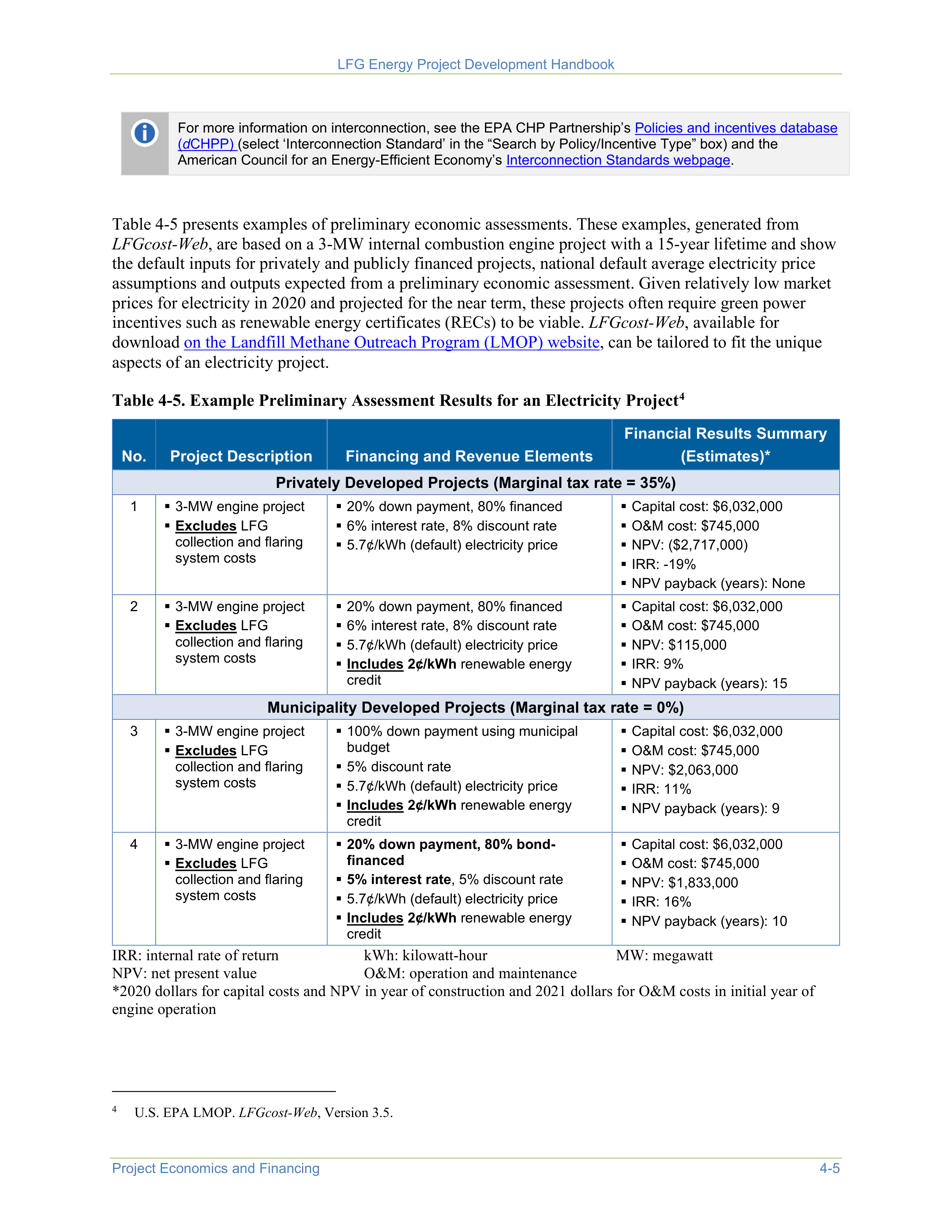

LFG Energy Project Development Handbook
Project Economics and Financing
4-5
For more information on interconnection, see the EPA CHP Partnership’s
Policies and incentives database
(
d
CHPP)
(select ‘Interconnection Standard’ in the “Search by Policy/Incentive Type” box) and the
American Council for an Energy-Efficient Economy’s
Interconnection Standards webpage
.
Table 4-5 presents examples of preliminary economic assessments. These examples, generated from
LFGcost-Web
, are based on a 3-MW internal combustion engine project with a 15-year lifetime and show
the default inputs for privately and publicly financed projects, national default average electricity price
assumptions and outputs expected from a preliminary economic assessment. Given relatively low market
prices for electricity in 2020 and projected for the near term, these projects often require green power
incentives such as renewable energy certificates (RECs) to be viable.
LFGcost-Web
, available for
download
on the Landfill Methane Outreach Program (LMOP) website
, can be tailored to fit the unique
aspects of an electricity project.
Table 4-5. Example Preliminary Assessment Results for an Electricity Project
4
4
U.S. EPA LMOP.
LFGcost-Web
, Version 3.5.
No.
Project Description
Financing and Revenue Elements
Financial Results Summary
(Estimates)*
Privately Developed Projects (Marginal tax rate = 35%)
1
3-MW engine project
Excludes
LFG
collection and flaring
system costs
20% down payment, 80% financed
6% interest rate, 8% discount rate
5.7¢/kWh (default) electricity price
Capital cost: $6,032,000
O&M cost: $745,000
NPV: ($2,717,000)
IRR: -19%
NPV payback (years): None
2
3-MW engine project
Excludes
LFG
collection and flaring
system costs
20% down payment, 80% financed
6% interest rate, 8% discount rate
5.7¢/kWh (default) electricity price
Includes 2¢/kWh
renewable energy
credit
Capital cost: $6,032,000
O&M cost: $745,000
NPV: $115,000
IRR: 9%
NPV payback (years): 15
Municipality Developed Projects (Marginal tax rate = 0%)
3
3-MW engine project
Excludes
LFG
collection and flaring
system costs
100% down payment using municipal
budget
5% discount rate
5.7¢/kWh (default) electricity price
Includes 2¢/kWh
renewable energy
credit
Capital cost: $6,032,000
O&M cost: $745,000
NPV: $2,063,000
IRR: 11%
NPV payback (years): 9
4
3-MW engine project
Excludes
LFG
collection and flaring
system costs
20% down payment, 80% bond-
financed
5% interest rate
, 5% discount rate
5.7¢/kWh (default) electricity price
Includes 2¢/kWh
renewable energy
credit
Capital cost: $6,032,000
O&M cost: $745,000
NPV: $1,833,000
IRR: 16%
NPV payback (years): 10
IRR: internal rate of return
kWh: kilowatt-hour
MW: megawatt
NPV: net present value
O&M: operation and maintenance
*2020 dollars for capital costs and NPV in year of construction and 2021 dollars for O&M costs in initial year of
engine operation
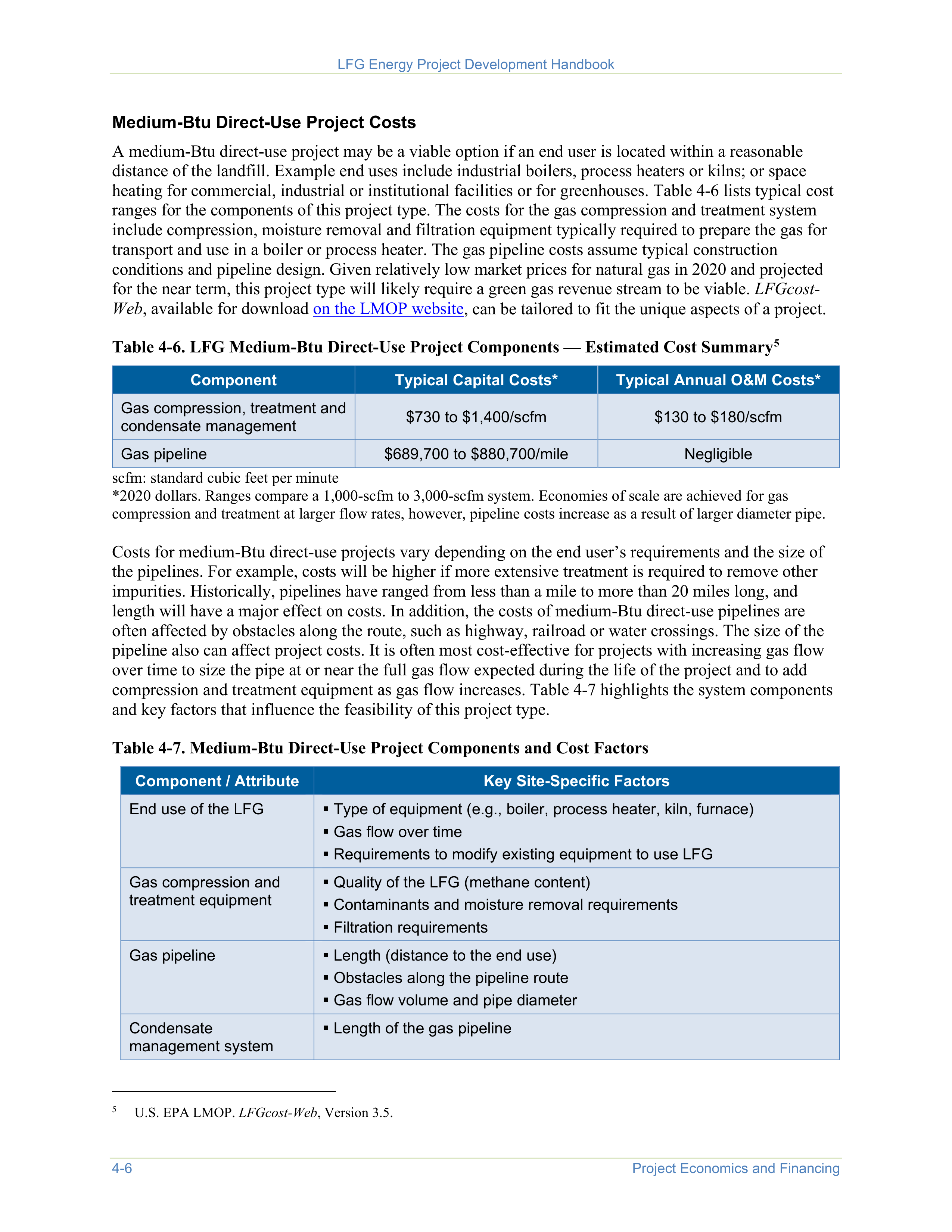
LFG Energy Project Development Handbook
4-6
Project Economics and Financing
Medium-Btu Direct-Use Project Costs
A medium-Btu direct-use project may be a viable option if an end user is located within a reasonable
distance of the landfill. Example end uses include industrial boilers, process heaters or kilns; or space
heating for commercial, industrial or institutional facilities or for greenhouses. Table 4-6 lists typical cost
ranges for the components of this project type. The costs for the gas compression and treatment system
include compression, moisture removal and filtration equipment typically required to prepare the gas for
transport and use in a boiler or process heater. The gas pipeline costs assume typical construction
conditions and pipeline design. Given relatively low market prices for natural gas in 2020 and projected
for the near term, this project type will likely require a green gas revenue stream to be viable.
LFGcost-
Web
, available for download
on the LMOP website
, can be tailored to fit the unique aspects of a project.
Table 4-6. LFG Medium-Btu Direct-Use Project Components — Estimated Cost Summary
5
5
U.S. EPA LMOP.
LFGcost-Web
, Version 3.5.
Component
Typical Capital Costs*
Typical Annual O&M Costs*
Gas compression, treatment and
condensate management
$730 to $1,400/scfm
$130 to $180/scfm
Gas pipeline
$689,700 to $880,700/mile
Negligible
scfm: standard cubic feet per minute
*2020 dollars. Ranges compare a 1,000-scfm to 3,000-scfm system. Economies of scale are achieved for gas
compression and treatment at larger flow rates, however, pipeline costs increase as a result of larger diameter pipe.
Costs for medium-Btu direct-use projects vary depending on the end user’s requirements and the size of
the pipelines. For example, costs will be higher if more extensive treatment is required to remove other
impurities. Historically, pipelines have ranged from less than a mile to more than 20 miles long, and
length will have a major effect on costs. In addition, the costs of medium-Btu direct-use pipelines are
often affected by obstacles along the route, such as highway, railroad or water crossings. The size of the
pipeline also can affect project costs. It is often most cost-effective for projects with increasing gas flow
over time to size the pipe at or near the full gas flow expected during the life of the project and to add
compression and treatment equipment as gas flow increases. Table 4-7 highlights the system components
and key factors that influence the feasibility of this project type.
Table 4-7. Medium-Btu Direct-Use Project Components and Cost Factors
Component / Attribute
Key Site-Specific Factors
End use of the LFG
Type of equipment (e.g., boiler, process heater, kiln, furnace)
Gas flow over time
Requirements to modify existing equipment to use LFG
Gas compression and
treatment equipment
Quality of the LFG (methane content)
Contaminants and moisture removal requirements
Filtration requirements
Gas pipeline
Length (distance to the end use)
Obstacles along the pipeline route
Gas flow volume and pipe diameter
Condensate
management system
Length of the gas pipeline
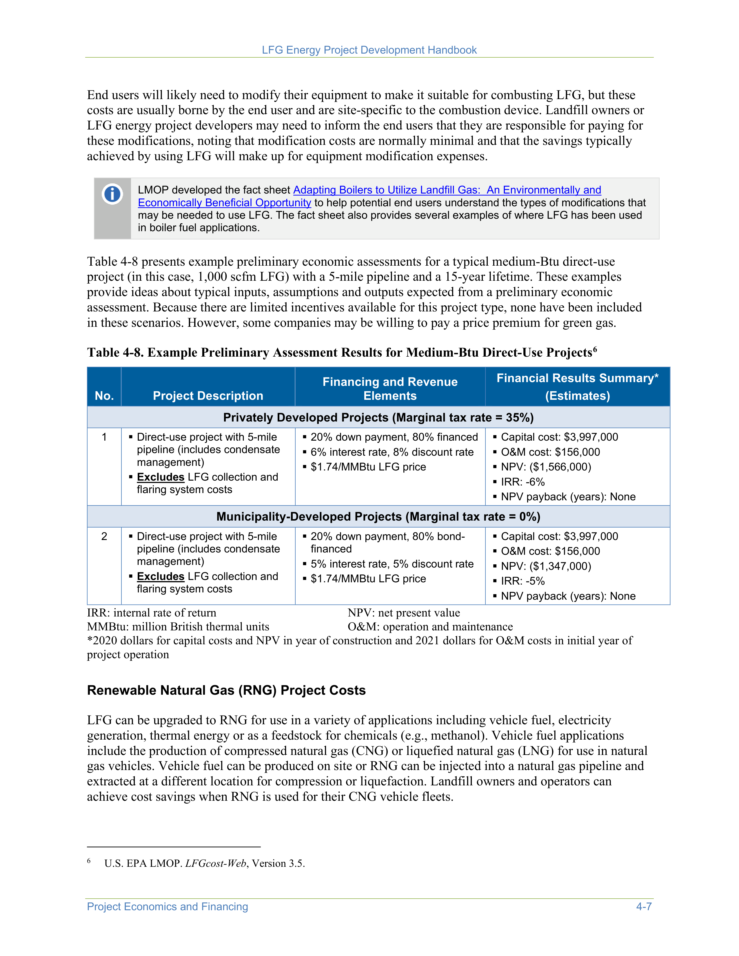

LFG Energy Project Development Handbook
Project Economics and Financing
4-7
End users will likely need to modify their equipment to make it suitable for combusting LFG, but these
costs are usually borne by the end user and are site-specific to the combustion device. Landfill owners or
LFG energy project developers may need to inform the end users that they are responsible for paying for
these modifications, noting that modification costs are normally minimal and that the savings typically
achieved by using LFG will make up for equipment modification expenses.
LMOP developed the fact sheet
Adapting Boilers to Utilize Landfill Gas: An Environmentally and
Economically Beneficial Opportunity
to help potential end users understand the types of modifications that
may be needed to use LFG. The fact sheet also provides several examples of where LFG has been used
in boiler fuel applications.
Table 4-8 presents example preliminary economic assessments for a typical medium-Btu direct-use
project (in this case, 1,000 scfm LFG) with a 5-mile pipeline and a 15-year lifetime. These examples
provide ideas about typical inputs, assumptions and outputs expected from a preliminary economic
assessment. Because there are limited incentives available for this project type, none have been included
in these scenarios. However, some companies may be willing to pay a price premium for green gas.
Table 4-8. Example Preliminary Assessment Results for Medium-Btu Direct-Use Projects
6
6
U.S. EPA LMOP.
LFGcost-Web
, Version 3.5.
No.
Project Description
Financing and Revenue
Elements
Financial Results Summary*
(Estimates)
Privately Developed Projects (Marginal tax rate = 35%)
1
Direct-use project with 5-mile
pipeline (includes condensate
management)
Excludes
LFG collection and
flaring system costs
20% down payment, 80% financed
6% interest rate, 8% discount rate
$1.74/MMBtu LFG price
Capital cost: $3,997,000
O&M cost: $156,000
NPV: ($1,566,000)
IRR: -6%
NPV payback (years): None
Municipality-Developed Projects (Marginal tax rate = 0%)
2
Direct-use project with 5-mile
pipeline (includes condensate
management)
Excludes
LFG collection and
flaring system costs
20% down payment, 80% bond-
financed
5% interest rate, 5% discount rate
$1.74/MMBtu LFG price
Capital cost: $3,997,000
O&M cost: $156,000
NPV: ($1,347,000)
IRR: -5%
NPV payback (years): None
IRR: internal rate of return
NPV: net present value
MMBtu: million British thermal units
O&M: operation and maintenance
*2020 dollars for capital costs and NPV in year of construction and 2021 dollars for O&M costs in initial year of
project operation
Renewable Natural Gas (RNG) Project Costs
LFG can be upgraded to RNG for use in a variety of applications including vehicle fuel, electricity
generation, thermal energy or as a feedstock for chemicals (e.g., methanol). Vehicle fuel applications
include the production of compressed natural gas (CNG) or liquefied natural gas (LNG) for use in natural
gas vehicles. Vehicle fuel can be produced on site or RNG can be injected into a natural gas pipeline and
extracted at a different location for compression or liquefaction. Landfill owners and operators can
achieve cost savings when RNG is used for their CNG vehicle fleets.
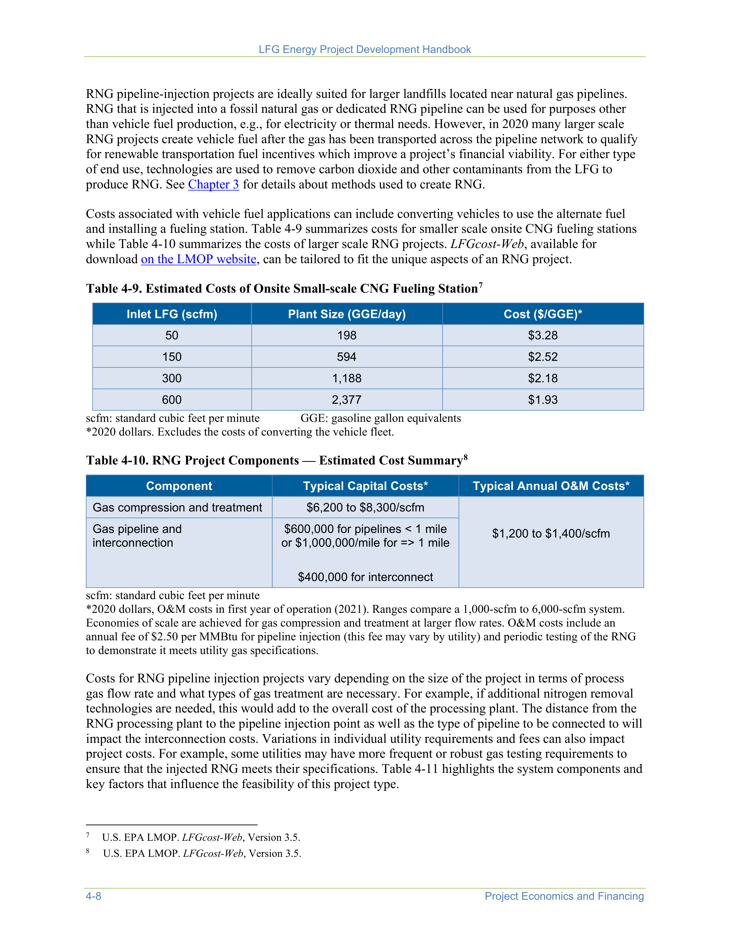
LFG Energy Project Development Handbook
4-8
Project Economics and Financing
RNG pipeline-injection projects are ideally suited for larger landfills located near natural gas pipelines.
RNG that is injected into a fossil natural gas or dedicated RNG pipeline can be used for purposes other
than vehicle fuel production, e.g., for electricity or thermal needs. However, in 2020 many larger scale
RNG projects create vehicle fuel after the gas has been transported across the pipeline network to qualify
for renewable transportation fuel incentives which improve a project’s financial viability. For either type
of end use, technologies are used to remove carbon dioxide and other contaminants from the LFG to
produce RNG. See
Chapter 3
for details about methods used to create RNG.
Costs associated with vehicle fuel applications can include converting vehicles to use the alternate fuel
and installing a fueling station. Table 4-9 summarizes costs for smaller scale onsite CNG fueling stations
while Table 4-10 summarizes the costs of larger scale RNG projects.
LFGcost-Web
, available for
download
on the LMOP website
, can be tailored to fit the unique aspects of an RNG project.
Table 4-9. Estimated Costs of Onsite Small-scale CNG Fueling Station
7
7
U.S. EPA LMOP.
LFGcost-Web
, Version 3.5.
Inlet LFG (scfm)
Plant Size (GGE/day)
Cost ($/GGE)*
50
198
$3.28
150
594
$2.52
300
1,188
$2.18
600
2,377
$1.93
scfm: standard cubic feet per minute
GGE: gasoline gallon equivalents
*2020 dollars. Excludes the costs of converting the vehicle fleet.
Table 4-10. RNG Project Components — Estimated Cost Summary
8
8
U.S. EPA LMOP.
LFGcost-Web
, Version 3.5.
Component
Typical Capital Costs*
Typical Annual O&M Costs*
Gas compression and treatment
$6,200 to $8,300/scfm
$1,200 to $1,400/scfm
Gas pipeline and
interconnection
$600,000 for pipelines < 1 mile
or $1,000,000/mile for => 1 mile
$400,000 for interconnect
scfm: standard cubic feet per minute
*2020 dollars, O&M costs in first year of operation (2021). Ranges compare a 1,000-scfm to 6,000-scfm system.
Economies of scale are achieved for gas compression and treatment at larger flow rates. O&M costs include an
annual fee of $2.50 per MMBtu for pipeline injection (this fee may vary by utility) and periodic testing of the RNG
to demonstrate it meets utility gas specifications.
Costs for RNG pipeline injection projects vary depending on the size of the project in terms of process
gas flow rate and what types of gas treatment are necessary. For example, if additional nitrogen removal
technologies are needed, this would add to the overall cost of the processing plant. The distance from the
RNG processing plant to the pipeline injection point as well as the type of pipeline to be connected to will
impact the interconnection costs. Variations in individual utility requirements and fees can also impact
project costs. For example, some utilities may have more frequent or robust gas testing requirements to
ensure that the injected RNG meets their specifications. Table 4-11 highlights the system components and
key factors that influence the feasibility of this project type.
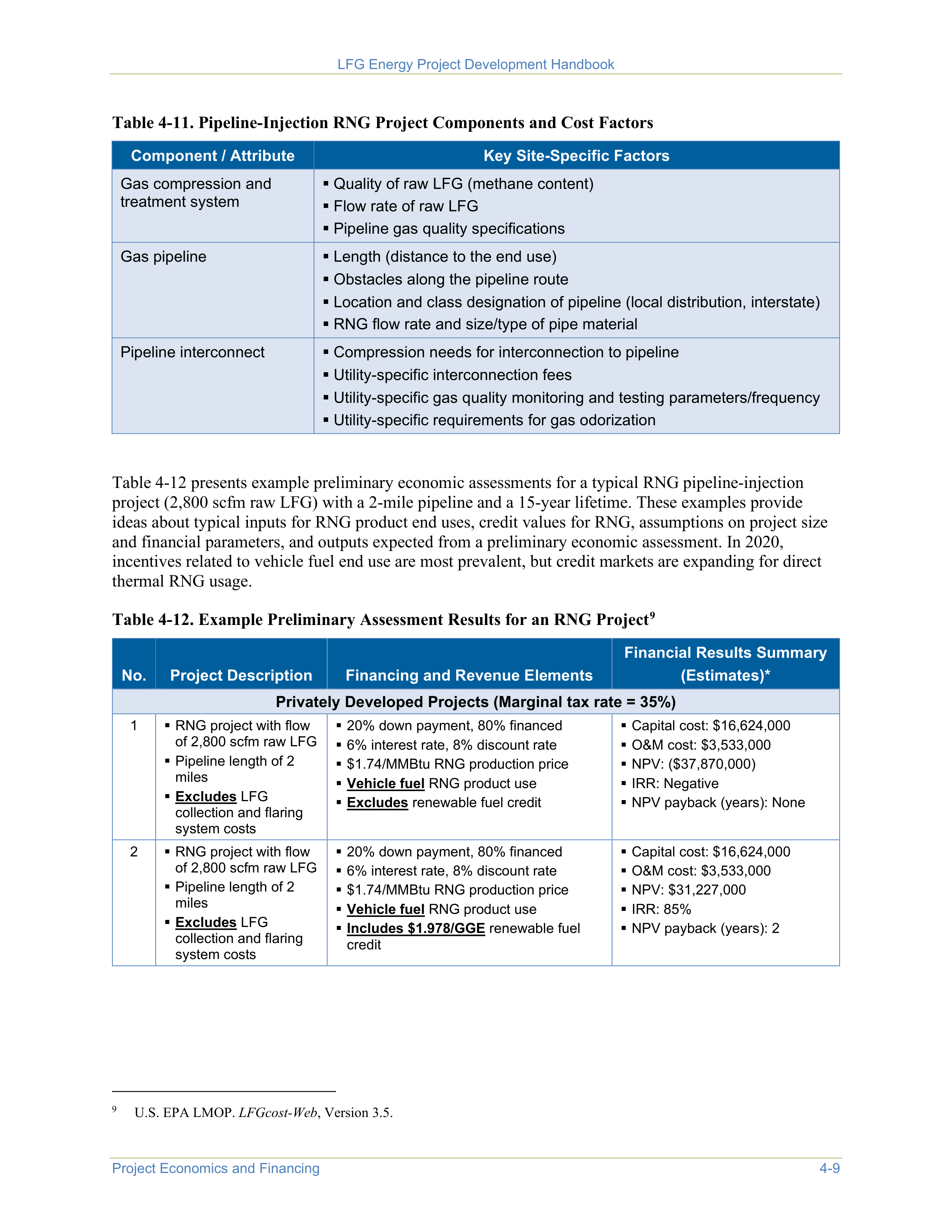
LFG Energy Project Development Handbook
Project Economics and Financing
4-9
Table 4-11. Pipeline-Injection RNG Project Components and Cost Factors
Component / Attribute
Key Site-Specific Factors
Gas compression and
treatment system
Quality of raw LFG (methane content)
Flow rate of raw LFG
Pipeline gas quality specifications
Gas pipeline
Length (distance to the end use)
Obstacles along the pipeline route
Location and class designation of pipeline (local distribution, interstate)
RNG flow rate and size/type of pipe material
Pipeline interconnect
Compression needs for interconnection to pipeline
Utility-specific interconnection fees
Utility-specific gas quality monitoring and testing parameters/frequency
Utility-specific requirements for gas odorization
Table 4-12 presents example preliminary economic assessments for a typical RNG pipeline-injection
project (2,800 scfm raw LFG) with a 2-mile pipeline and a 15-year lifetime. These examples provide
ideas about typical inputs for RNG product end uses, credit values for RNG, assumptions on project size
and financial parameters, and outputs expected from a preliminary economic assessment. In 2020,
incentives related to vehicle fuel end use are most prevalent, but credit markets are expanding for direct
thermal RNG usage.
Table 4-12. Example Preliminary Assessment Results for an RNG Project
9
9
U.S. EPA LMOP.
LFGcost-Web
, Version 3.5.
No.
Project Description
Financing and Revenue Elements
Financial Results Summary
(Estimates)*
Privately Developed Projects (Marginal tax rate = 35%)
1
RNG project with flow
of 2,800 scfm raw LFG
Pipeline length of 2
miles
Excludes
LFG
collection and flaring
system costs
20% down payment, 80% financed
6% interest rate, 8% discount rate
$1.74/MMBtu RNG production price
Vehicle fuel
RNG product use
Excludes
renewable fuel credit
Capital cost: $16,624,000
O&M cost: $3,533,000
NPV: ($37,870,000)
IRR: Negative
NPV payback (years): None
2
RNG project with flow
of 2,800 scfm raw LFG
Pipeline length of 2
miles
Excludes
LFG
collection and flaring
system costs
20% down payment, 80% financed
6% interest rate, 8% discount rate
$1.74/MMBtu RNG production price
Vehicle fuel
RNG product use
Includes $1.978/GGE
renewable fuel
credit
Capital cost: $16,624,000
O&M cost: $3,533,000
NPV: $31,227,000
IRR: 85%
NPV payback (years): 2
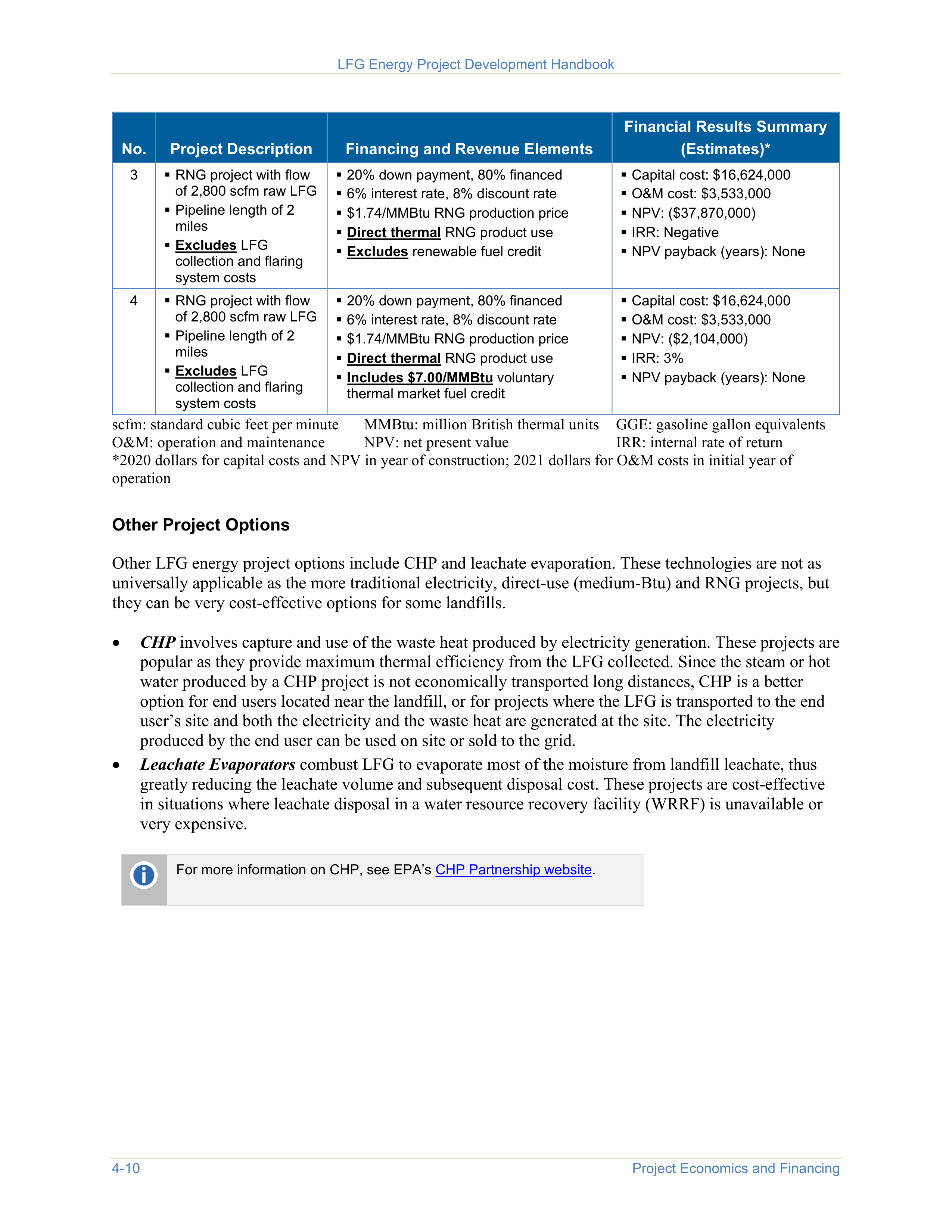

LFG Energy Project Development Handbook
4-10
Project Economics and Financing
No.
Project Description
Financing and Revenue Elements
Financial Results Summary
(Estimates)*
3
RNG project with flow
of 2,800 scfm raw LFG
Pipeline length of 2
miles
Excludes
LFG
collection and flaring
system costs
20% down payment, 80% financed
6% interest rate, 8% discount rate
$1.74/MMBtu RNG production price
Direct thermal
RNG product use
Excludes
renewable fuel credit
Capital cost: $16,624,000
O&M cost: $3,533,000
NPV: ($37,870,000)
IRR: Negative
NPV payback (years): None
4
RNG project with flow
of 2,800 scfm raw LFG
Pipeline length of 2
miles
Excludes
LFG
collection and flaring
system costs
20% down payment, 80% financed
6% interest rate, 8% discount rate
$1.74/MMBtu RNG production price
Direct thermal
RNG product use
Includes $7.00/MMBtu
voluntary
thermal market fuel credit
Capital cost: $16,624,000
O&M cost: $3,533,000
NPV: ($2,104,000)
IRR: 3%
NPV payback (years): None
scfm: standard cubic feet per minute
MMBtu: million British thermal units
GGE: gasoline gallon equivalents
O&M: operation and maintenance
NPV: net present value
IRR: internal rate of return
*2020 dollars for capital costs and NPV in year of construction; 2021 dollars for O&M costs in initial year of
operation
Other Project Options
Other LFG energy project options include CHP and leachate evaporation. These technologies are not as
universally applicable as the more traditional electricity, direct-use (medium-Btu) and RNG projects, but
they can be very cost-effective options for some landfills.
•
CHP
involves capture and use of the waste heat produced by electricity generation. These projects are
popular as they provide maximum thermal efficiency from the LFG collected. Since the steam or hot
water produced by a CHP project is not economically transported long distances, CHP is a better
option for end users located near the landfill, or for projects where the LFG is transported to the end
user’s site and both the electricity and the waste heat are generated at the site. The electricity
produced by the end user can be used on site or sold to the grid.
•
Leachate Evaporators
combust LFG to evaporate most of the moisture from landfill leachate, thus
greatly reducing the leachate volume and subsequent disposal cost. These projects are cost-effective
in situations where leachate disposal in a water resource recovery facility (WRRF) is unavailable or
very expensive.
For more information on CHP, see EPA’s
CHP Partnership website
.



LFG Energy Project Development Handbook
Project Economics and Financing
4-11
4.2 Step 2: Estimate Energy Sales Revenues and Other Revenue
Streams or Incentives
Electricity Project Revenues
The primary revenue source for typical electricity projects is the sale of electricity to a local utility or
private user. Revenue potential is affected by the electricity buy-back rates (the rate at which the local
utility purchases electricity generated by the LFG energy project), which depend on several factors
specific to the local electric utility and the type of contract negotiated with the project. Forecasted buy-
back rates for 2021 range from 2.8 to 8.8 cents per kWh.
10
Occasionally, the electricity is sold to a third
party (private user) at a rate that is attractive when compared with the local retail electricity rates.
10
U.S. Energy Information Administration. Annual Energy Outlook 2020. Table 54. Electric Power Projections by Electricity
Market Module Region. Prices by service category, generation.
https://www.eia.gov/outlooks/aeo/data/browser/#/?id=62-
AEO2020&cases=ref2020&sourcekey=0
.
It is important to consider the amount of electricity
generated from the LFG that the landfill will use
directly to support onsite operations. These “avoided”
electricity costs are, in effect, the costs of the electricity
that the landfill does not have to purchase from a utility.
Avoided electricity is not valued at the buy-back rate,
but at the rate the landfill is charged to purchase
electricity (the retail rate). The retail rate is often
significantly higher than the buy-back rate.
The
LFGcost-Web
economic feasibility
assessment tool accommodates several
common types of project credits including
a direct cash grant, a GHG reduction
credit expressed in dollars per metric ton
of carbon dioxide equivalent, a REC
expressed in dollars per kWh and a
renewable fuel credit expressed in dollars
per gallon.
LFG is recognized as a renewable, or “green,” energy
resource, so additional revenues may be available through premium pricing, tax credits, greenhouse gas
(GHG) credit trading or incentive payments. These revenues can be reflected in an economic analysis in
various ways but converting to a cents per kWh format is typically most useful.
Medium-Btu Direct-Use and RNG Project Revenues
One source of revenue for direct-use and RNG projects is the sale of LFG to the end user, so the price of
LFG contributes to determination of project revenues. Often, LFG sales prices are indexed to the price of
natural gas (for example, 70 percent of the New York Mercantile Exchange (NYMEX) or Henry Hub
natural gas price indices for medium-Btu projects), but prices will vary depending on site-specific
negotiations, the type of contract and other factors.
The Henry Hub, the largest centralized point for natural gas spot and futures trading in the United States,
interconnects nine interstate and four intrastate pipelines. The Henry Hub is owned and operated by
Sabine Pipe Line, LLC, a subsidiary of EnLink Midstream Partners LP. The Sabine Pipe Line starts near
Port Arthur, Texas, and ends in Vermilion Parish, Louisiana, at the Henry Hub near the town of Erath.
NYMEX, the world’s largest physical commodity futures exchange, uses the Henry Hub as the point of
delivery for its natural gas futures contract. The NYMEX gas futures contract began trading on April 3,
1990 and is currently traded 72 months into the future. NYMEX deliveries at the Henry Hub are treated in
the same way as cash-market transactions.
LFG Energy Project Development Handbook
4-12
Project Economics and Financing
The current natural gas price is depressed as a result of abundant domestic supply and efficient methods
of production. In 2020, the average Henry Hub spot price for the year was $2.04 per MMBtu. Modest
increases in natural gas prices are expected as electric power consumption of natural gas increases.
11
11
U.S. Energy Information Administration. Natural Gas. May 2021. Henry Hub Natural Gas Spot Price.
https://www.eia.gov/dnav/ng/hist/rngwhhdm.htm
.
A main source of revenue for projects in which the RNG is used as vehicle fuel are federal and state low-
carbon fuel credits. This type of credit significantly improves an RNG project’s financial viability, as
shown in the comparison of Examples No. 1 and No. 2 in Table 4-11.
Incentives and Funding
Federal and state tax incentives, loans and grants are available that may provide additional funding or
revenue for LFG energy projects. Below is a brief summary of those incentives; LMOP’s
Resources for
Funding LFG Energy Projects page
presents additional details on available incentives and where to find
more information on them.
•
Electricity Portfolio Standards:
Premium pricing is often available for renewable electricity
(including from LFG) that is included in a green power program, through a Renewable Portfolio
Standard, a Renewable Portfolio Goal, a Clean Energy Standard, a Clean Energy Goal or a voluntary
utility green pricing program. LMOP’s
State
Funding
Resources for
LFG Energy Projects
page
provides
more details about these types of resources that potentially apply to LFG electricity projects.
•
RECs:
RECs are sold through voluntary markets to consumers seeking to reduce their environmental
footprint. They are typically offered in 1 megawatt-hour (MWh) units, and are sold by LFG electricity
generators to industries, commercial businesses, institutions and private citizens who wish to achieve
a corporate renewable energy portfolio goal or to encourage renewable energy. If the electricity
produced by an LFG energy project is not being sold as part of a utility green power program or green
pricing program, the project owner may be able to sell RECs through voluntary markets to generate
additional revenue. EPA’s Green Power Partnership provides a state-by-state directory of green
power providers in the
Green Power locator
.
•
Tax Advantages:
Tax credits, tax exemptions and other tax incentives, as well as federal and state
low-cost bonds and loan programs, may provide funding resources for an LFG energy project. For
example, Section 45 of the Internal Revenue Code provides a 1.3 cent per kWh production tax credit
for electricity generated at privately owned LFG electricity projects that commenced construction by
December 31, 2021. More details about these incentives can be found at LMOP’s
Resources for
Funding LFG Energy Projects page
.
•
Grant Programs:
Grants offered by many federal and state programs may also provide funding for
LFG energy projects. A comprehensive and searchable listing of federal and state grant programs is
available on the
Database of State Incentives for Renewables & Efficiency (DSIRE) website
.
•
State and Regional Incentives:
Many state and regional government entities are establishing their
own GHG and renewable energy initiatives. For comprehensive and up-to-date information about
state and regional incentives and policies for renewable energy resources, including LFG, visit the
DSIRE website
.


LFG Energy Project Development Handbook
Project Economics and Financing
4-13
•
Renewable Fuel Standard (RFS)
:
LFG is considered a qualified
pathway under the federal RFS program. Administered by EPA,
the program requires obligated parties (including refiners or
importers of gasoline or diesel fuel) to meet a Renewable Volume
Obligation (RVO) based on the amount of petroleum-based fuels
they produce or import annually. One way to meet compliance requirements is by obtaining credits
known as Renewable Identification Numbers (RINs). In July 2014, EPA modified the existing
pathway to specify that CNG or LNG is the fuel and the biogas is the feedstock. Further, EPA
allowed fuels derived from landfill biogas to qualify as a cellulosic biofuel (D3), rather than only an
advanced biofuel (D5). EPA also added a new renewable electricity pathway for electricity used in
electric vehicles. Annually, EPA sets the renewable volume requirements, which may offer a growing
market for LFG.
For LFG (biogas), 77,000
Btu is equal to 1 gallon
equivalent or 1 RIN.
•
California Low Carbon Fuel Standard (LCFS):
The LCFS is administered by the
California Air
Resources Board
and is a market-based mechanism to encourage cleaner low-carbon fuels in
California vehicles. The LCFS accounts for the life cycle GHG emissions of fuel, and any fuel with a
certified fuel pathway with a lower carbon intensity for the standard such as biogas-based CNG
derived from landfill or digester gas can generate and sell credits. The goal of the LCFS is to achieve
a 20 percent carbon intensity reduction between 2010 and 2030 for the transportation fuel sold in the
state. Oregon and Washington have established programs similar to the LCFS. See
An Overview of
Renewable Natural Gas from Biogas
for more information about the LCFS and other state fuel
standards.
•
Nitrogen Oxides Cap-and-Trade:
Some LFG energy projects may qualify for participation in
nitrogen oxides cap-and-trade programs. The revenues for these incentives vary by state and will
depend on factors such as the allowances allocated to each project, the price of allowances on the
market and the end use of the LFG. CHP projects typically receive more revenue based on credit for
avoided use as boiler fuel. See the EPA document
Environmental Revenue Streams for Combined
Heat and Power
for additional information.
•
Voluntary GHG Credits:
Bilateral trading and GHG credit sales are other voluntary sources of
revenue. Bilateral trades are project-specific and are negotiated directly between a buyer and seller of
GHG credits. In these cases, corporate entities or public institutions, such as universities, may wish to
reduce their “carbon footprint” or meet internal sustainability goals, but do not have a means to
develop their own project. Therefore, a buyer may help finance a specific project in exchange for the
credit of offsetting GHG emissions from their organization. These projects may be simple
transactions between a single buyer and seller (for example, the project developer), or may involve
brokers that “aggregate” credits from several small projects for sale to large buyers. Bilateral trading
programs often involve certification and quantification of GHG reductions to ensure the validity of
the trade and, as a result, there can be rigorous monitoring and recordkeeping requirements. The
additional revenue is likely to justify these additional efforts.
•
Voluntary Renewable Thermal Certificates (RTCs):
Similar to RECs in the electricity markets,
RTCs are sold through voluntary markets to consumers looking to lower the environmental impact of
their heating and cooling use. One RTC is issued for each dekatherm of renewable thermal generation
and includes the environmental attributes. Eligible renewable thermal technologies include RNG and
renewable hydrogen.
M-RETs
is a tracking system for credits including RTCs and provides more
information on its website.


LFG Energy Project Development Handbook
4-14
Project Economics and Financing
Example
Golden Triangle Regional Solid Waste Management Authority Power Generation Project,
Mississippi.
Golden Triangle staff spent several years evaluating LFG energy project
possibilities and seeking solutions to overcome challenges associated with the site’s remote
location, lack of nearby potential end users and projected high installation costs. In 2010, Golden
Triangle arranged an agreement with the Tennessee Valley Authority’s Generation Partners
program to secure premium green power prices for the LFG energy. Within 1 year, the project
became the first LFG electricity project in Mississippi, with a rated capacity of just under 1 MW of
renewable energy.
4.3
Step 3: Assess Economic Feasibility
Once the costs and revenues for a project have been
determined, and the project is considered technically viable,
an economic feasibility analysis should be performed.
Project developers can use
LFGcost-Web
to evaluate the
preliminary economic feasibility.
Analyses performed
using
LFGcost-Web
are considered estimates and should
be used for guidance only.
When a more detailed analysis
is undertaken, however, many LFG energy consulting
companies and LFG energy project developers rely on their own financial
pro forma
programs, which
may enable a more detailed analysis for a specific project.
A financial
pro forma
is a spreadsheet
model to estimate cash flow based on
the costs and revenue streams and
provides a more accurate estimate of
the probable economic performance
over the lifetime of the project.
To perform the analysis, calculate and compare the expenses and revenue on a year-by-year basis for the
life of the project. The following elements should be included, most of which can be obtained from
LFGcost-Web
(or a more detailed site-specific cost analysis) and an analysis of the revenue streams:
•
Project capital and O&M cost data
•
Operation summary — electricity generated, Btu delivered, gas consumed
•
Financing costs — the amount financed, interest rate, cost to service the debt each year
•
Inflation rates (can alter O&M costs, especially if the product is sold at a fixed price over a term)
•
Product price escalation rates — increases or decreases in the price of electricity or LFG
•
Revenue calculation — sales of electricity and other revenue from incentives and markets
•
Risk sensitivity and cost uncertainty factors — unpredictable conditions that affect project operations
and increasing or decreasing capital or O&M costs
•
Tax considerations — applicable taxes or tax credits that affect revenue streams
A
pro forma
analysis will calculate measures of economic performance that are used to assess financial
feasibility, such as:
•
IRR
— The rate that balances the overall costs of the project with the revenue earned over the
lifetime of the project such that the net present value of the investment is equal to zero.
•
NPV at year of construction
— First year monetary value that is equivalent to the various cash flows,
based on the discount rate. In other words, the NPV is calculated as the present value of a stream of
current and future benefits minus the present value of a stream of current and future costs.
•
Years to breakeven
— This value is the number of years for the project to pay for itself.
•
Annual cash flow
—
Total revenue from the project minus expenses, including O&M and capital
amortization costs. Essentially this measure represents the income the project generates in a year.
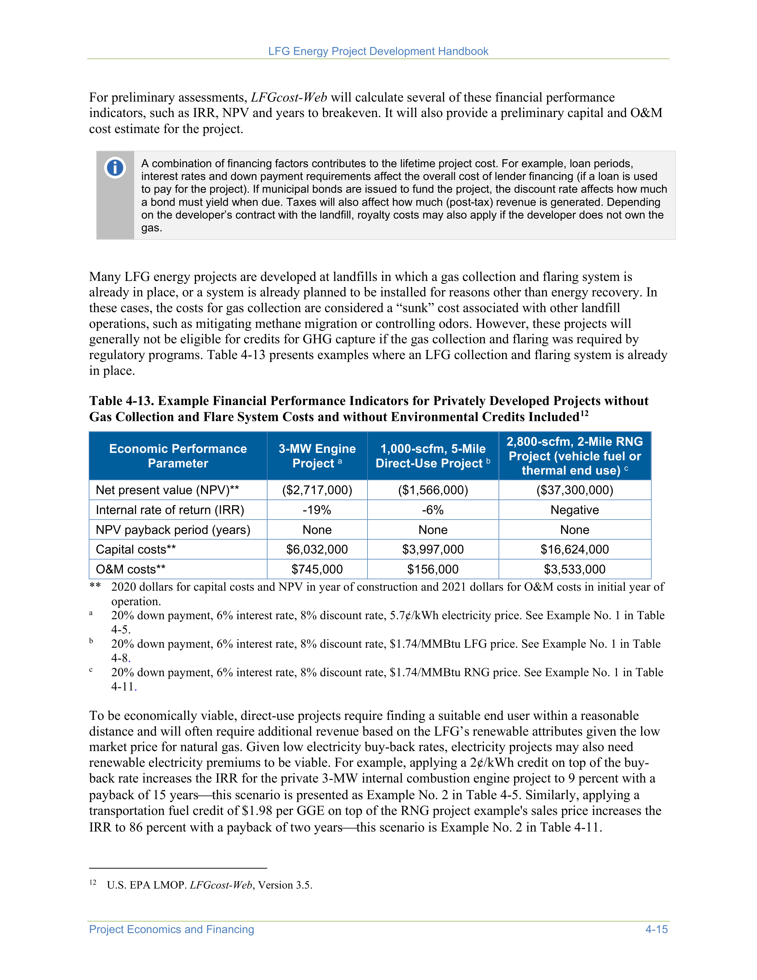

LFG Energy Project Development Handbook
Project Economics and Financing
4-15
For preliminary assessments,
LFGcost-Web
will calculate several of these financial performance
indicators, such as IRR, NPV and years to breakeven. It will also provide a preliminary capital and O&M
cost estimate for the project.
A combination of financing factors contributes to the lifetime project cost. For example, loan periods,
interest rates and down payment requirements affect the overall cost of lender financing (if a loan is used
to pay for the project). If municipal bonds are issued to fund the project, the discount rate affects how much
a bond must yield when due. Taxes will also affect how much (post-tax) revenue is generated. Depending
on the developer’s contract with the landfill, royalty costs may also apply if the developer does not own the
gas.
Many LFG energy projects are developed at landfills in which a gas collection and flaring system is
already in place, or a system is already planned to be installed for reasons other than energy recovery. In
these cases, the costs for gas collection are considered a “sunk” cost associated with other landfill
operations, such as mitigating methane migration or controlling odors. However, these projects will
generally not be eligible for credits for GHG capture if the gas collection and flaring was required by
regulatory programs. Table 4-13 presents examples where an LFG collection and flaring system is already
in place.
Table 4-13. Example Financial Performance Indicators for Privately Developed Projects without
Gas Collection and Flare System Costs and without Environmental Credits Included
12
12
U.S. EPA LMOP.
LFGcost-Web
, Version 3.5.
Economic Performance
Parameter
3-MW Engine
Project
a
1,000-scfm, 5-Mile
Direct-Use Project
b
2,800-scfm, 2-Mile RNG
Project (vehicle fuel or
thermal end use)
c
Net present value (NPV)**
($2,717,000)
($1,566,000)
($37,300,000)
Internal rate of return (IRR)
-19%
-6%
Negative
NPV payback period (years)
None
None
None
Capital costs**
$6,032,000
$3,997,000
$16,624,000
O&M costs**
$745,000
$156,000
$3,533,000
** 2020 dollars for capital costs and NPV in year of construction and 2021 dollars for O&M costs in initial year of
operation.
a
20% down payment, 6% interest rate, 8% discount rate, 5.7¢/kWh electricity price. See Example No. 1 in Table
4-5.
b
20% down payment, 6% interest rate, 8% discount rate, $1.74/MMBtu LFG price. See Example No. 1 in Table
4-8
.
c
20% down payment, 6% interest rate, 8% discount rate, $1.74/MMBtu RNG price. See Example No. 1 in Table
4-11
.
To be economically viable, direct-use projects require finding a suitable end user within a reasonable
distance and will often require additional revenue based on the LFG’s renewable attributes given the low
market price for natural gas. Given low electricity buy-back rates, electricity projects may also need
renewable electricity premiums to be viable. For example, applying a 2¢/kWh credit on top of the buy-
back rate increases the IRR for the private 3-MW internal combustion engine project to 9 percent with a
payback of 15 years
this scenario is presented as Example No. 2 in Table 4-5. Similarly, applying a
transportation fuel credit of $1.98 per GGE on top of the RNG project example's sales price increases the
IRR to 86 percent with a payback of two years
this scenario is Example No. 2 in Table 4-11.

LFG Energy Project Development Handbook
4-16
Project Economics and Financing
Finally, it is important to bear the developer’s objectives in mind. Often, municipalities do not expect the
same IRR and payback periods as private entities. Corporations, on the other hand, usually have
competing uses for their limited capital and prefer to invest in projects with the greatest IRR and to
quickly recover the capital investment in only a couple of years. The financial requirements of the parties
involved in developing a project must be considered in evaluating economic feasibility and selecting
financing mechanisms. A project at a publicly owned landfill that is not financially attractive to a project
developer could still be implemented through self-development or partnering arrangements.
See
Chapter 5
and
Chapter 6
for more information on project structures and development options.
4.4
Step 4: Compare All Economically Feasible Options and Select
Winners
After the initial economic analysis for each project option has been completed, a comparison should be
made to decide which one best meets the project objectives. After the comparison, some options may
emerge as clearly uncompetitive and not worth further consideration; alternatively, there may be one
option that is clearly the superior choice and warrants a more detailed investigation. It is likely, however,
that multiple energy project options are viable, and it may be necessary to compare the economic analysis
of each to select the most promising option, bearing in mind any non-price factors as discussed below.
A side-by-side economic comparison can be used to rank the financial performance of each option to
select a winner. This comparison should incorporate several economic measures in the ranking, since no
single measure can guarantee a project’s economic success. For example, projects could be ranked based
on the NPV after taxes, making sure that the IRR requirements are satisfied, or that the debt incurred to
finance the project is acceptable. Results may show that the project with the highest IRR has capital and
O&M costs that exceed available financing. If so, a lower IRR project that costs less and is easier to
finance may be the best option.
Conducting a sensitivity analysis can help the project developer understand the risks associated with
different scenarios. For example, projects that carry lower risks can be more attractive to investors even if
IRRs are higher because of the level of risk each one presents for certain factors. If a specific risk is
identified, the investor or developer can use financial operations, such as hedging, to mitigate certain (but
not all) risks.
At this point, important non-price factors should be considered, such as risks related to the attainment of
emission limits or the use of new technology. Non-price factors that affect the project may not be
quantifiable by the economic analysis. For example, the project might be located in a severe non-
attainment area where stringent emission limits are in place, making it difficult and expensive to obtain a
permit for a new combustion device. In this case, finding a direct user that could supplant some of its
current fuel use with LFG might be a more viable project. In another example, project options that use
proven technologies may incur lower risk than options using newer technologies. The new technologies
might offer the potential for a greater return on investment, but the risk may influence the financing
available and may result in a higher interest loan.
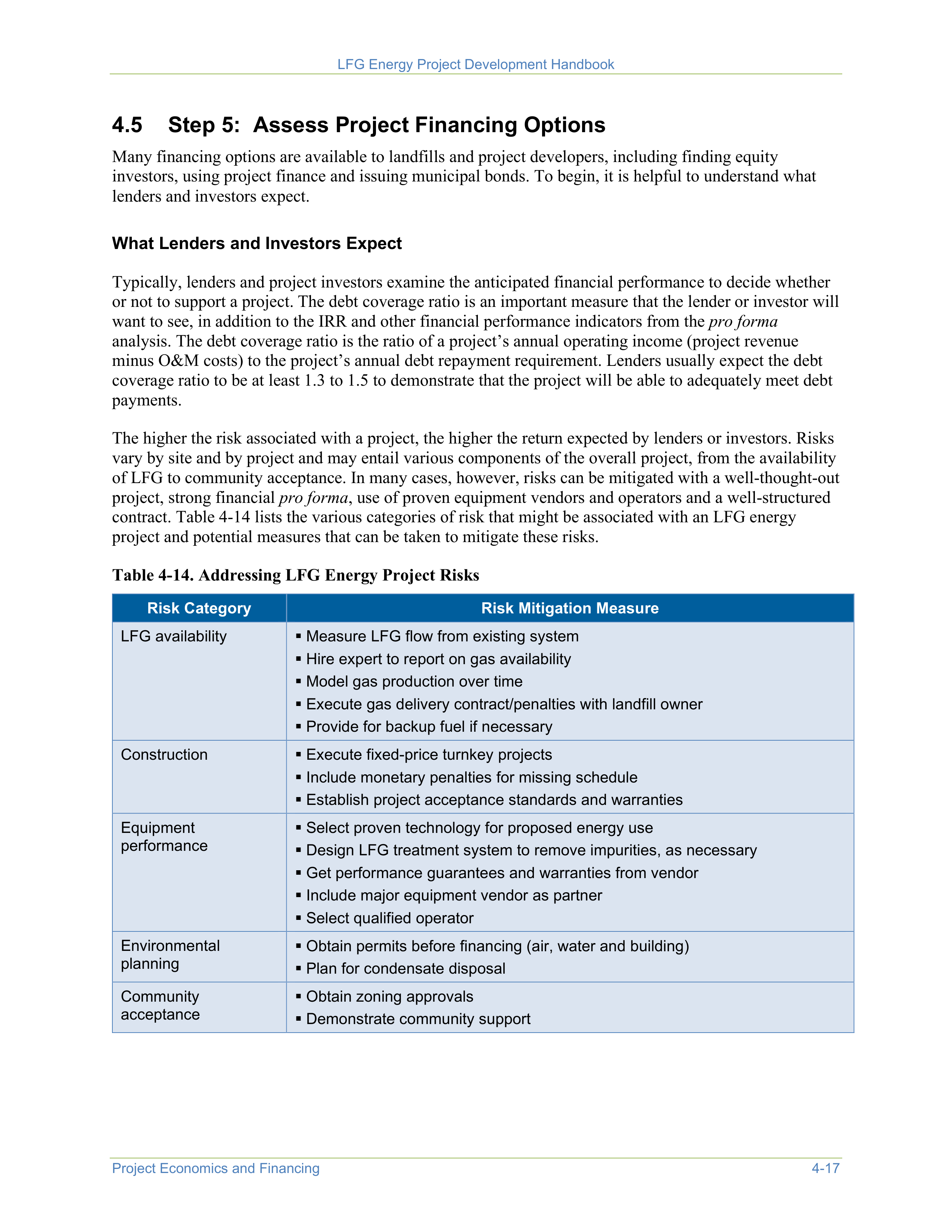
LFG Energy Project Development Handbook
Project Economics and Financing
4-17
4.5
Step 5: Assess Project Financing Options
Many financing options are available to landfills and project developers, including finding equity
investors, using project finance and issuing municipal bonds. To begin, it is helpful to understand what
lenders and investors expect.
What Lenders and Investors Expect
Typically, lenders and project investors examine the anticipated financial performance to decide whether
or not to support a project. The debt coverage ratio is an important measure that the lender or investor will
want to see, in addition to the IRR and other financial performance indicators from the
pro forma
analysis. The debt coverage ratio is the ratio of a project’s annual operating income (project revenue
minus O&M costs) to the project’s annual debt repayment requirement. Lenders usually expect the debt
coverage ratio to be at least 1.3 to 1.5 to demonstrate that the project will be able to adequately meet debt
payments.
The higher the risk associated with a project, the higher the return expected by lenders or investors. Risks
vary by site and by project and may entail various components of the overall project, from the availability
of LFG to community acceptance. In many cases, however, risks can be mitigated with a well-thought-out
project, strong financial
pro forma
, use of proven equipment vendors and operators and a well-structured
contract. Table 4-14 lists the various categories of risk that might be associated with an LFG energy
project and potential measures that can be taken to mitigate these risks.
Table 4-14. Addressing LFG Energy Project Risks
Risk Category
Risk Mitigation Measure
LFG availability
Measure LFG flow from existing system
Hire expert to report on gas availability
Model gas production over time
Execute gas delivery contract/penalties with landfill owner
Provide for backup fuel if necessary
Construction
Execute fixed-price turnkey projects
Include monetary penalties for missing schedule
Establish project acceptance standards and warranties
Equipment
performance
Select proven technology for proposed energy use
Design LFG treatment system to remove impurities, as necessary
Get performance guarantees and warranties from vendor
Include major equipment vendor as partner
Select qualified operator
Environmental
planning
Obtain permits before financing (air, water and building)
Plan for condensate disposal
Community
acceptance
Obtain zoning approvals
Demonstrate community support
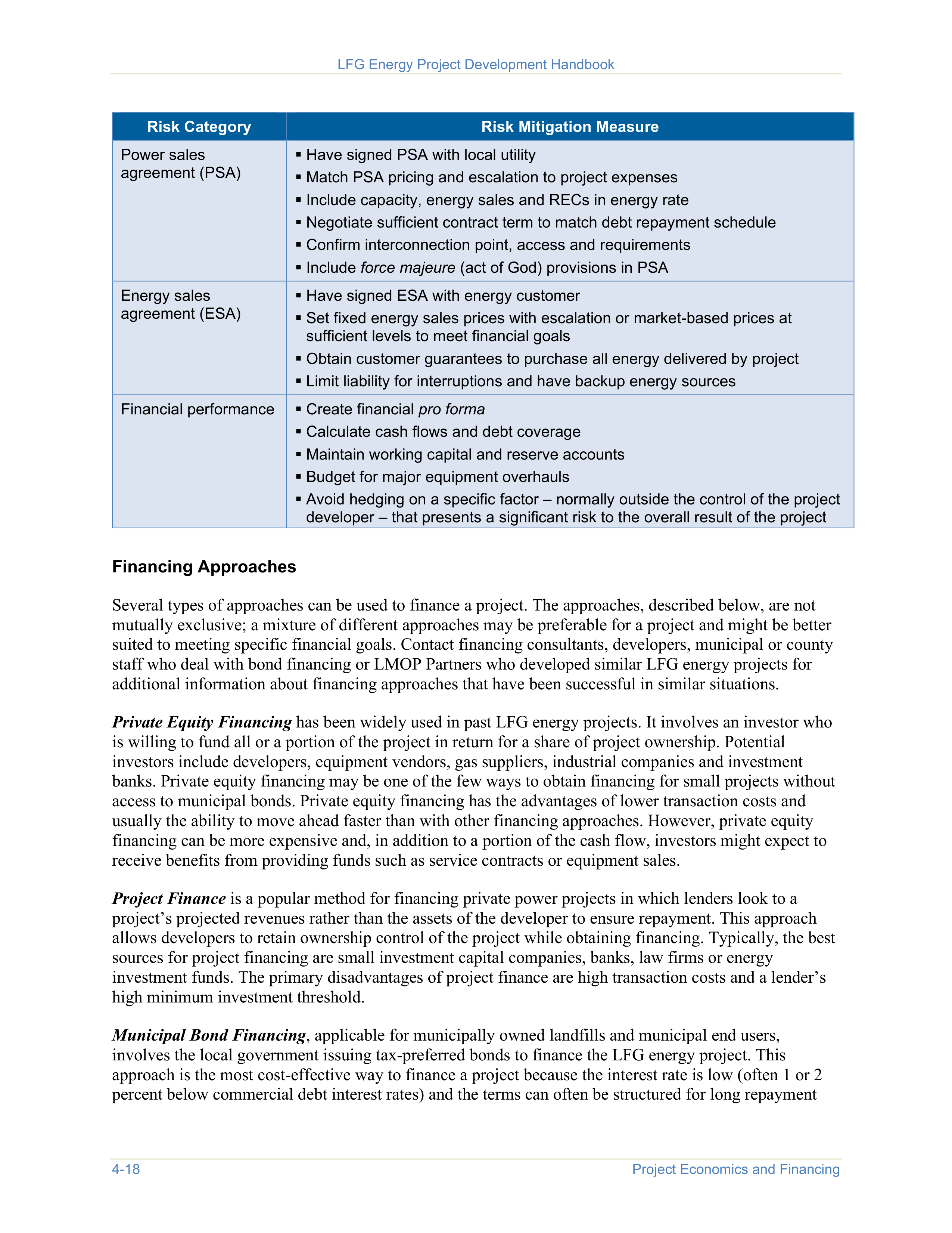
LFG Energy Project Development Handbook
4-18
Project Economics and Financing
Risk Category
Risk Mitigation Measure
Power sales
agreement (PSA)
Have signed PSA with local utility
Match PSA pricing and escalation to project expenses
Include capacity, energy sales and RECs in energy rate
Negotiate sufficient contract term to match debt repayment schedule
Confirm interconnection point, access and requirements
Include
force majeure
(act of God) provisions in PSA
Energy sales
agreement (ESA)
Have signed ESA with energy customer
Set fixed energy sales prices with escalation or market-based prices at
sufficient levels to meet financial goals
Obtain customer guarantees to purchase all energy delivered by project
Limit liability for interruptions and have backup energy sources
Financial performance
Create financial
pro forma
Calculate cash flows and debt coverage
Maintain working capital and reserve accounts
Budget for major equipment overhauls
Avoid hedging on a specific factor – normally outside the control of the project
developer – that presents a significant risk to the overall result of the project
Financing Approaches
Several types of approaches can be used to finance a project. The approaches, described below, are not
mutually exclusive; a mixture of different approaches may be preferable for a project and might be better
suited to meeting specific financial goals. Contact financing consultants, developers, municipal or county
staff who deal with bond financing or LMOP Partners who developed similar LFG energy projects for
additional information about financing approaches that have been successful in similar situations.
Private Equity Financing
has been widely used in past LFG energy projects. It involves an investor who
is willing to fund all or a portion of the project in return for a share of project ownership. Potential
investors include developers, equipment vendors, gas suppliers, industrial companies and investment
banks. Private equity financing may be one of the few ways to obtain financing for small projects without
access to municipal bonds. Private equity financing has the advantages of lower transaction costs and
usually the ability to move ahead faster than with other financing approaches. However, private equity
financing can be more expensive and, in addition to a portion of the cash flow, investors might expect to
receive benefits from providing funds such as service contracts or equipment sales.
Project Finance
is a popular method for financing private power projects in which lenders look to a
project’s projected revenues rather than the assets of the developer to ensure repayment. This approach
allows developers to retain ownership control of the project while obtaining financing. Typically, the best
sources for project financing are small investment capital companies, banks, law firms or energy
investment funds. The primary disadvantages of project finance are high transaction costs and a lender’s
high minimum investment threshold.
Municipal Bond Financing
, applicable for municipally owned landfills and municipal end users,
involves the local government issuing tax-preferred bonds to finance the LFG energy project. This
approach is the most cost-effective way to finance a project because the interest rate is low (often 1 or 2
percent below commercial debt interest rates) and the terms can often be structured for long repayment
LFG Energy Project Development Handbook
Project Economics and Financing
4-19
periods. However, municipalities can face barriers to issuing bonds, such as private business use and
securities limitations, public disclosure requirements and high financial performance requirements.
Project developers should check with the state or municipality where the bond is issued to determine the
terms for securing bond financing and the method for qualifying for the bond. Developers also should
consider consulting with a tax professional before deciding on whether tax-exempt or taxable bonds
should be secured.
Direct Municipal Funding
, possibly the lowest-cost financing available, uses the operating budget of the
city, county, landfill authority or other municipal government to fund the LFG energy project. This
approach eliminates the need to obtain outside financing or project partners, and it avoids delays caused
by the extensive project evaluations usually required by lenders or partners. However, many
municipalities may not have a budget that is sufficient to finance a project or may have many projects
competing for scarce resources. Delays and complications may also arise if public approval is required.
Lease Financing
provides a means for the project owner or operator to lease all or part of the LFG
energy project assets. This arrangement usually allows the transfer of tax benefits or credits to an entity
that can best make use of them. Lease arrangements can allow for the user to purchase the assets or
extend the lease when the term of the lease has been fulfilled. The benefit of lease financing is that it frees
up capital funds of the owner or operator but allowing them control of the project. The disadvantages
include complex accounting and liability issues and loss of tax benefits to the project owner or operator.
Examples
Anne Arundel County’s Millersville Landfill Electricity Project, Maryland.
After more than
12 years of exploring options and negotiating agreements, Anne Arundel County implemented
a 3.2-MW rated capacity electricity project. The first LFG energy project located in the county, it
generates green power for the local grid while providing revenue for county-wide energy
efficiency and solid waste projects. A combination of local bond sales, $2 million in American
Recovery and Reinvestment Act (ARRA) funding and cooperation among local, state and
federal government contributed to the success of the project.
Orange County’s Olinda Alpha Landfill Combined Cycle Project, California.
Creative
financing was key to implementation of this project that produced the second-largest LFG-
fueled power plant (32.5 MW rated capacity) in the United States. Financing included a $10
million ARRA grant from the Department of Energy and a Section 1603 grant from the U.S.
Treasury. Positive impacts on the economy stem from local green power usage by the City of
Anaheim, annual county LFG revenues of $2.75 million, and manufacture of all major
equipment components in the United States.



Landfill Gas Contracts and Regulations
5-1
Landfill owners and operators establish contractual arrangements with end users for the sale of landfill
gas (LFG), electricity and other environmental attributes generated by an LFG energy project. The
agreements establish the project’s value and are critical to its long-term success. These agreements are
essential for projects that rely on financing. Lenders and investors are particularly interested in the
structure of contractual agreements and potential risks, which directly affect the terms of the financing.
Therefore, landfill owner/operators and project developers should thoroughly evaluate the elements of all
potential contractual agreements. This chapter discusses three
categories of contracts: power sales agreements (PSAs) (for
electricity generation projects), LFG purchase agreements and
environmental attribute agreements. An overview of applicable
regulations and permits is also provided.
Most LFG energy projects are
“must run,” meaning that they
operate continuously and electricity
is not dispatched by a system
operator. Operators of dispatchable
LFG electricity projects can take
advantage of price variations in the
electricity market by bringing units
online or taking units offline, in
response to demand. Dispatchable
LFG electricity projects are typically
managed from a central location via
remote connection to the facility’s
supervisory control and data
acquisition (SCADA) systems.
5.1
Power Sales Agreements
Traditionally, electricity generated from an LFG energy
project has been sold through a power purchase agreement
(PPA) to investor-owned utilities (IOUs) that provide electrical
service in the region where the project is located. Since the late
1990s, non-regulated entities (such as independent power
producers, co-operatives, municipalities, power marketers and
power purchasers) have had greater access to the electricity
grid, creating competitive electricity markets in many states
and regions. With the advent of these competitive markets, electricity providers offer many more options
for the purchase of electricity.
Landfill owners and project developers should consider these options carefully. Electricity and other
attributes, including capacity, renewable attributes of the power and ancillary services, can be sold
individually or as a “bundled” product. Furthermore, many of these electrical elements can be sold on
either a daily basis or for a fixed term.
PPA.
Historically, the most common structure has been to sell the electricity to an IOU, co-operative or
municipal entity through a PPA. The electricity, including capacity, is sold to the IOU at a fixed price,
with some measure of escalation or at an indexed price based on an estimate of short-run avoided cost or
publicly available local market price mechanism. Environmental attributes related to the electricity
generated by the LFG energy project may or may not be included in the PPA. Environmental attributes
are associated with electricity produced by renewable energy sources and can be referred to as “green
power.” Executed PPAs can address the transaction of the electricity alone or might include some or all of
the green power attributes. These agreements are typically negotiated or obtained through a competitive
bidding process. The terms of these contracts can vary greatly, from 1 to 15 years. Entities providing
financing are most comfortable with PPAs because of their predictable revenue stream. Financing entities
prefer a PPA term equal to or longer than the term of the financing.

LFG Energy Project Development Handbook
5-2
Landfill Gas Contracts and Regulations
Power Sales Agreement with a Power Marketer or Wholesale Buyer.
Electricity generated by an
LFG
energy project can be sold to power marketers, wholesale buyers or other entities eligible to buy or sell
electricity in states and regions with robust electricity markets where electricity pricing is transparent. The
contract terms can vary widely; two common terms are:
•
A fixed “bundled” rate that typically includes energy and capacity, and may include renewable
attributes of power, for a fixed term of 2 to 15 years. The rate can be adjusted annually for inflation.
•
A variable rate for electricity (energy or capacity) at a premium or discount (depending on market
conditions) to a publicly available market price for a fixed term. Rates may include a floor and a
ceiling price. Rates may adjust daily, monthly, quarterly, bi-annually or annually. The term can be
fixed for a period of 1 to 10 years.
Examples
Examples of states/regions that have robust electricity markets and transparent pricing include:
•
PJM Interconnection
•
New York Independent System Operator
•
California Independent System Operator
Selling Directly into a Market.
Project developers or owners can sell directly into electricity markets for
the market price for energy and capacity. The price for energy is usually estimated theoretically a day
ahead based on bids received, then updated in real time several times per hour (every 5 to 15 minutes) by
the system operator. The market price is set by the lowest marginal cost of the next generating unit to be
dispatched and provide power to the system. Capacity is typically bid and prices are established for longer
time periods — typically 1 to 6 months, but this time varies. The renewable attributes of the power are not
typically sold in these markets, but these markets may track and verify the production of these attributes.
Net Metering.
As of June 2020, 40 states, Washington D.C., and four U.S. territories have mandatory
rules related to net metering.
1
Net metering allows consumers to offset their electrical use with
appropriately sized renewable electric generation located on site. As a result, the total amount of
electricity supplied to the site is reduced, yielding a lower “net” amount of electricity provided by the
power company. The operator pays for this “net” amount of power supplied. In some cases, onsite
generation may exceed onsite electricity needs. Net metering provisions have emerged to allow operators
to sell excess electricity to the local power company and receive credit for the amount of electricity
provided back to the electrical grid. This approach allows the LFG energy project to generate and use
electricity on site while maintaining access to grid electricity and creates a source of revenue for the LFG
energy project through the sale of excess electricity. States set their own net metering regulations and
typically limit the capacity of the generation.
1
Database of State Incentives for Renewables & Efficiency (DSIRE). June 2020.
https://ncsolarcen-
prod.s3.amazonaws.com/wp-content/uploads/2020/06/DSIRE_Net_Metering_June2020.pdf
.
A
summary map of net metering policies
is available from the DSIRE website.
Other Consideration — Electric Grid Interconnection
In addition to contracting issues, LFG energy developers or owners must carefully consider the
complexity, cost and timing of interconnecting to the electric grid. Grid interconnection can be the most




LFG Energy Project Development Handbook
Landfill Gas Contracts and Regulations
5-3
important issue in evaluating the feasibility of a project. Factors that drive interconnection costs and
timing include:
•
Amount of electricity (megawatts [MW]) the developer wants to connect to the grid
•
Size and capacity of surrounding distribution (12 to 15 kilovolt [kV]) and medium tension
(20 to 69 kV) distribution lines
•
Location of the distribution substation
•
Interconnection procedures and regulations
•
Utility requirements (such as communications, protection and control)
These factors are highly dependent on the project’s location and the
utility’s experience and willingness to interconnect with LFG energy and
other distributed generation projects. In some regions and states, regional
transmission operators (RTOs) and regulators are trying to make the
interconnection process for small renewable projects more streamlined,
transparent and cost-effective. Early on in the project development cycle,
the utility completes an interconnection feasibility study (paid for by the
developer), which will define many of these issues. An interconnect
agreement will be required with the utility, as well as agreements for the
design and construction of the interconnection.
Costs and timing can vary
substantially among
projects, so LFG energy
developers should begin
the interconnection
process as early as
possible and engage
interconnection experts
with local experience.
5.2
LFG Purchase Agreements
LFG is typically sold for one of four purposes:
1.
For use as a substitute for other fuels to create hot air, hot water or steam (e.g., to fire boilers,
kilns or furnaces). This is typically referred to as a direct-use project or a medium-British thermal
unit (Btu) project.
2.
To power an LFG-fired electricity generation facility.
3.
For injection into a natural gas distribution or transmission pipeline, after purification to natural
gas pipeline standards (typically referred to as a renewable natural gas [RNG] project); or for use
as vehicle fuel (typically compressed natural gas [CNG] or liquefied natural gas [LNG]).
4.
LFG can also be sold to a third-party developer for the rights to use it for a variety of uses.
Direct-Use Sales of Medium-Btu LFG
Direct-use projects use three basic types of contracts between the end
user and either the landfill owner or project developer/owner: fixed
price, indexed price and a fixed/indexed hybrid approach. These
contracts are usually set on a Btu-delivered basis. Delivered LFG is
commonly sold at a discount to natural gas prices as a result of the
following factors:
•
Requirements to transport LFG and modify equipment (such as boilers) to use LFG
•
Potentially higher operation and maintenance (O&M) costs because LFG has more impurities than
natural gas
•
Need for the end user to have backup fuels
Indexed pricing bases the
cost of LFG on a discount of
current natural gas prices.



LFG Energy Project Development Handbook
5-4
Landfill Gas Contracts and Regulations
The level of discount is determined by the level of investment required to construct and operate the
project and by how these costs are distributed among the participating parties.
Fixed Price Contracts
.
A guaranteed fixed price contract establishes a fixed price for the gas for a certain
length of time. This price usually escalates over time to account for inflation. The initial price for LFG is
typically set at or below the average market price for natural gas and is based on costs to implement the
LFG energy project and the return on investment required by the participating parties. Because of the
volatility of natural gas prices, fixed price contracts for LFG are less common.
Indexed Sales Contracts
.
Indexed sales contracts use natural gas
prices to determine the value of the LFG. Normally, the “city gate
price” of natural gas is used, which is the price paid by the local
natural gas utility and can vary by region. In some cases, price
incentives result in discounts to a market price for natural gas.
Discounts can vary significantly depending on such factors as local
Renewable Portfolio Standard (RPS) targets, costs of transporting
natural gas, the local utility’s strategy for incorporating alternative
fuels, the amount of investment required for a specific project and the
parties responsible for necessary investments.
When natural gas prices are
low, indexed sales contracts
may not be viable without
additional incentives. For
example, if biogas is being
upgraded to be used as CNG
for vehicle fuel, incentives are
present to use LFG as a
supplement to natural gas.
Indexed sales contracts may
be more attractive to LFG
owners in the future if natural
gas prices increase.
When negotiating price with the end user, the owner of the LFG
should consider that the end user may not have access to the natural
gas wholesale pipeline pricing indicated in most commonly available
indices (e.g., Henry Hub). Buyers must pay additional costs for
transportation, infrastructure construction and distribution of the natural gas, which can result in prices
that exceed the wholesale indices. Because of the volatility of natural gas prices, indexed LFG sales
contracts are highly variable in terms of revenue; however, they can provide the project developer or
owner with adequate revenue and the end user with considerable savings.
To limit price risks on both sides of the contract agreement, indexed contracts typically include provisions
for maximum and minimum pricing (e.g., when the government puts a legal limit on how high the price
of a product can be [ceiling] and when the government puts a legal limit on how low a product can be
[floor]). Setting a floor price limit is essential to reducing the risk for the seller of the LFG, particularly if
the seller is making a significant investment. A financing entity typically requires setting a floor price to
ensure that debt payments can be made in all market conditions. A price ceiling is essential if the LFG
buyer is making a significant investment; it also provides an additional incentive to use LFG. Typically, if
one party is requiring a floor price, the counterparty asks for a ceiling price, or vice versa.
Learn more about
floor prices
and
ceiling prices
.
Hybrid Contracts.
LFG sales contracts have also been implemented in other creative ways to minimize
risk and maximize economic benefits. One such option is a hybrid of the two previous types of contracts.
In an example hybrid contract, a fixed price contract is implemented for a certain period of time (e.g.,
until the capital investment is recovered) and then converted into an indexed price contract. Sales costs
depend on the level of investment and equity participants.
LFG contracts may include a minimum guarantee on the quality and amount of LFG to be delivered and a
minimum guarantee on the amount of gas that will be consumed (known as a “take or pay” clause). LFG
energy project developers or owners should consider factors such as equipment and potential wellfield
uncertainties when they agree to a minimum guarantee on gas delivery. In addition, landfills that are
LFG Energy Project Development Handbook
Landfill Gas Contracts and Regulations
5-5
closed or closing in the near future should be cautious about setting aggressive gas quantity or quality
limits. Conversely, the energy user should consider any routine plant shutdowns or other possible
disruptions that would limit the need for gas when setting a minimum consumption guarantee.
LFG Sales to an Electrical Generation Project
These contracts are similar to those developed under a direct-use project application. The contractual
relationships between the LFG energy project owner or operator (the electricity generator) and the
purchaser of the electricity are provided in greater detail in Section 5.1.
RNG Sales
LFG that is purified to natural gas pipeline standards can be injected into a natural gas distribution or
transmission line subject to regulatory approval. Whether RNG is sold into a regional distribution line or
transmission line, there are three standard contracts typically associated with the injection, distribution
and sale of RNG:
1)
Pipeline Interconnection Agreement, which sets requirements for gas quality, periodic sampling
and other elements associated with injection of RNG into the pipeline;
2)
North American Energy Standards Board (NAESB) Gas Sale Contract, which contains standard
terms on the sale/purchase of RNG; and
3)
Transaction Confirmation Agreement (often appended to the Gas Sale Contract), which can
include specifics on the monetization of environmental attributes associated with RNG.
Interconnection agreements and NAESB contracts apply only to RNG projects that involve injection into
a gas distribution or transmission line. For projects with adjacent CNG fuel stations (typically onsite or
nearby), only a Transaction Confirmation Agreement is used. This agreement outlines the specifications
for the CNG quality and also any agreed-to volumes of the CNG to be consumed. Once ready for delivery
at the station, the CNG is typically sold to fleet customers at a price similar to that of CNG derived from
fossil natural gas.
RNG may ultimately be sold to a natural gas supplier, marketer or distributor at a fixed price or at an
indexed natural gas price appropriate for the location or point of delivery, but all of the primary details are
wrapped into the above listed contract types.
Generally, most RNG producers will work with a third-party auditor to register and verify the facility to
produce environmental attributes, and coordinate with a gas marketer to sell credits under the RFS or a
state-level transportation fuel credit market (see Section 5.3).
Royalty Payments
When a third-party developer is involved in a project, the developer will typically pay the landfill owner a
royalty fee in exchange for the rights to use the LFG for energy. The royalty fee sales agreement value
will vary depending on how the developer and the landfill owner share project expenses and risks, but in
general, the developer will make a minimum payment for access to the LFG and share a percentage of the
upside revenue associated with the sale of LFG energy into higher-value end use markets.

LFG Energy Project Development Handbook
5-6
Landfill Gas Contracts and Regulations
To purify LFG to natural gas pipeline standards, the concentrations of carbon dioxide, oxygen, nitrogen
and other impurities (such as volatile organic compounds, hazardous air pollutants, hydrogen sulfide
and siloxanes) must be reduced. For more information about treating LFG to pipeline standards, see
Chapter 3
and
An Overview of Renewable Natural Gas from Biogas
.
5.3
Environmental Attribute Agreements
An LFG energy project developer may sell a project’s environmental attributes for additional revenue or
to provide more revenue to the landfill owner. Environmental attributes can be sold together or separately,
depending on the market and the nature of the contract entered into by the landfill owner or LFG energy
project owner. The attributes available to an LFG energy project will vary depending on how the gas is
used. Broadly, there are two types of environmental attributes:
•
Direct – destruction of methane (a potent greenhouse gas [GHG])
•
Indirect – displacement of fossil fuel use by LFG use, a renewable energy resource
All contracting parties should ensure that ownership of the environmental attributes, including the rights
to the GHG emission reductions, are clearly defined. Historically, agreements have been relatively clear
about ownership of LFG rights; however, contract language has not been as clear with respect to evolving
environmental markets and incentives such as renewable energy certificates (RECs), tax credits and GHG
credits. A clear definition of which party owns each of the environmental attributes of the LFG is critical
for new project agreements and amendments to older agreements.
For information about renewable energy tax credits or other incentives to improve project financial
feasibility, see
Chapter 4
.
GHG Credits Derived from the Destruction of Methane in LFG
The GHG reductions achieved by the destruction of methane in LFG have market value and can be sold in
voluntary and compliance markets. Essentially, an entity that wants, or is required, to reduce its GHG
emissions can indirectly fund LFG collection and control projects through the purchase of GHG emission
reduction credits from landfills. These GHG credits are traded in units of metric tons of carbon dioxide
equivalent. Currently, GHG credits are traded in either a compliance or voluntary market; no single
market nor single standard for the trade of GHG credits currently exists.
For a landfill’s project to qualify for a GHG emission credit, the destruction of LFG must be “additional,”
meaning that the LFG must be collected and controlled voluntarily and cannot be required under
regulations such as EPA’s New Source Performance Standards (NSPS) for municipal solid waste (MSW)
landfills. Generally, a project does not qualify for GHG credits if the landfill is required to collect and
control LFG under any local, state or federal regulations for control of emissions, odors or gas migration.
Although buyers and markets vary, most require the LFG collection system to have been installed
recently. Some buyers and markets will accept LFG collection systems that commenced operation as
early as January 1, 1999.
Voluntary Markets
.
Most GHG transactions currently take place in a voluntary market, which is
composed of sellers, buyers, brokers and aggregators who are voluntarily trading GHG credits with the



LFG Energy Project Development Handbook
Landfill Gas Contracts and Regulations
5-7
goal of reducing the buyer’s carbon footprint. Voluntary market transactions occur in several over-the-
counter (OTC) markets.
2
2
State of the Voluntary Carbon Markets 2020: The Only Constant is Change. Forest Trends’ Ecosystem Marketplace. December
2020.
https://www.forest-trends.org/publications/state-of-the-voluntary-carbon-markets-2020-the-only-constant-is-change/
.
Participants in voluntary OTC markets, or firms investing in GHG credit projects, will sign agreements
with landfill owners to obtain the right to the GHG credits and may provide the investment funds for the
LFG collection system in some situations. The structure of these agreements is variable and will primarily
depend on the level of equity, if any, provided by the party interested in procuring the GHG credits.
Contract structures may provide ongoing revenue sharing or may allow the equity provider to recover
their investment before revenue is shared with the landfill. This structure would apply for agreements
where the GHG investment firm provides equity for all or part of a gas collection and control system.
GHG agreements where equity is provided are typically longer-term agreements (up to 10 years) to
minimize capital recovery risk by the investor. Simple GHG credit purchase agreements where significant
equity is not provided can have a much wider range in the length of the agreement. These non-equity
GHG purchase agreements may address the transaction of a discrete amount of previously generated
GHG credits, or may provide a longer-term (or forward) agreement for the rights to future GHG credit
generation.
Voluntary GHG markets are established when an entity (or group) takes
the initiative to offer one in light of a perceived unmet level of interest
among potential buyers and sellers of GHG credits. The continued
existence of a given voluntary market is a reflection of adequate levels of
seller and buyer participation. These voluntary markets are typically
independent of each other, and no one standardized methodology or
protocol exists among these markets for determining eligibility of credits.
These voluntary markets operate using several different standards and
protocols for determining project eligibility and verifying the GHG
credits. Carbon standards include the
Verified Carbon Standard
, the
Gold
Standard
,
The Climate Registry
and the
American Carbon Registry
.
Protocols outline project eligibility, monitoring, recordkeeping, quantification and reporting requirements.
GHG methodologies applicable to landfill projects in the voluntary markets currently include:
•
Climate Action Reserve Landfill Project Protocol Version 5.0
•
Greenhouse Gas Protocol
•
EPA Center for Corporate Climate Leadership
A
standard
is the overall
framework of a GHG
program, whereas a
protocol
is a specific set of
requirements that outline
how GHG credits are
developed for a specific
project, such as an LFG
energy project.
Once the methane destruction from the LFG energy project has been quantified using the selected
protocol, it must be converted into metric tons of carbon dioxide equivalent for trading. To calculate this
conversion, the amount of methane destroyed is multiplied by the global warming potential of methane,
which can range from 28 to 36 depending on which GHG standard or protocol is used. Once a third party
has verified the GHG credits, they may become verified emission reductions, carbon financial instruments
or other protocol-defined instruments, depending on the market or the protocol used by the buyer.
The GHG credits generated by the voluntary collection and destruction of LFG at a landfill can be a
significant revenue stream for the owner of the LFG rights, as described in
Chapter 4
.
Compliance Markets
.
Compliance markets have been established in some states and regions of the
United States. The
Regional Greenhouse Gas Initiative (RGGI)
is a cooperative effort by Northeastern
and Mid-Atlantic states to reduce carbon dioxide emissions in the region. Participating states include



LFG Energy Project Development Handbook
5-8
Landfill Gas Contracts and Regulations
Connecticut, Delaware, Maine, Maryland, Massachusetts, New Hampshire, New Jersey, New York,
Rhode Island, Vermont and Virginia. RGGI states propose to regulate carbon dioxide emissions from
power plants through a regional cap-and-trade system, although some of the states in RGGI do not accept
applications for any offset project types. RGGI has established its own emissions trading program and a
specific methodology for landfills to provide GHG offsets to this market.
California enacted a bill (AB-32) in 2006 that required the
Air Resources Board
to establish rules to
reduce GHG emissions. The Board implemented an enforceable cap-and-trade program in 2012.
3
The
Western Climate Initiative
— including California and Canadian provinces — developed ‘model rules’ to
form the basis of a regional GHG reduction program, including a cap-and-trade system. As these and
other mandatory GHG reduction programs mature, they might create additional opportunity for revenue
streams from LFG energy projects, depending on whether they are designed to accommodate GHG
offsets from landfills.
3
California Environmental Protection Agency, Air Resources Board, Cap-and-Trade Program.
https://ww3.arb.ca.gov/cc/capandtrade/capandtrade.htm
.
Renewable Energy Attributes of LFG Energy Projects
LFG energy project developers and owners have opportunities to sell the renewable energy attributes of
an LFG electricity project through several potential markets. Transactions in these markets provide value
based on the reduction in fossil fuel used to create energy when LFG energy projects are implemented.
Many of these transactions involve a broker or marketer that can ensure all the requirements for tracking
and verifying attributes are met.
Transportation Fuel Credits.
There are federal and state programs that incentivize using renewably
sourced vehicle fuels. The federal
Renewable Fuel Standard (RFS)
provides an opportunity for projects in
which LFG is used to create vehicle fuel to generate credits known as Renewable Identification Numbers
(RINs). RINs are purchased by refiners or importers of gasoline or diesel fuel through offtake agreements
to help them meet annual renewable transportation fuel requirements. California, Oregon and Washington
have programs to reduce the carbon intensity of transportation
fuel consumed within each state relative to a baseline. Vehicle
fuel from LFG qualifies for these state-level credits, which
are purchased by obligated entities within each state. See
An
Overview of Renewable Natural Gas from Biogas
for more
information about the LCFS and other state fuel standards.
DSIRE logo
Up-to-date information about
RPSs is available from the
Database of State Incentives for
Renewables & Efficiency (DSIRE)
website.
These transportation fuel environmental attributes can be sold
using a variety of agreement types, including: fixed price
which often deeply discounts the credit value given the high
risk and market variability; variable revenue share agreement in which the project owner and marketer
share revenue depending on market value; and hybrid structure which includes a floor price for the project
owner’s credit value plus a shared fraction with the marketer or broker.
RECs
.
Many states have an electricity portfolio standard such as an RPS. A state RPS requires an
electrical supplier, provider or distributor who sells to retail customers (an “electric services provider”) to
include a minimum percentage of electricity from renewable generation. Typically, the electric services
provider can meet the minimum percentage by purchasing renewable generation attributes from anywhere
within the state or regional electric control area. Many state RPS programs group or “tier” the various
types of renewable technologies based on which technologies a state wants to encourage. The RPS
requirements create competitive markets for renewable attributes from renewable energy projects,

LFG Energy Project Development Handbook
Landfill Gas Contracts and Regulations
5-9
including LFG-fired generation. RECs are the tradable units that allow electric services providers to meet
RPS requirements; a typical REC represents the environmental attributes of 1 megawatt-hour (MWh) of
electrical generation delivered to the grid. Pricing for RECs varies greatly by state, depending on the RPS
regulations and supply and demand for a given renewable generation technology. RECs can also be sold
through voluntary markets, more commonly in states without RPS requirements or access to RPS
programs within the region. LFG electricity project developers and owners should investigate their
options to sell RECs generated by the project and should consider obtaining the assistance of a broker or
consultant to maximize the value of the REC. Many utilities have already met their obligations for the
upcoming years and may not be interested in buying more RECs. It is therefore important that project
developers contact all potential buyers to make sure the project being considered can generate sufficient
revenues to be financially viable.
U.S. EPA Green Power Partnership
The
Green Power Partnership
is a voluntary program that encourages
organizations to buy green power as a way to reduce the environmental
impacts associated with purchased electricity use. As of 2020, the
partnership had more than 700 partner organizations voluntarily
purchasing more than 70 billion kilowatt-hours of green power annually.
GHG Displacement Credits
.
An LFG energy project can generate GHG emission reduction credits by
displacing more carbon-intensive forms of electric generation on the grid, such as coal and natural gas.
Typically, LFG electricity-generating projects may not simultaneously sell RECs and obtain GHG
emission reduction credits for the displacement of fossil fuels, because this is considered selling the same
environmental attribute twice. However, LFG electricity projects that do not sell RECs (and do not sell
the renewable attributes of the energy to their power purchaser by other means) can receive GHG
emission reduction credits for the destruction of the LFG if their PSAs allow for these sales. Additionally,
some programs provide GHG credits for displacement of fossil fuel use by LFG energy projects that
produce thermal energy.
Agreements to sell renewable energy attributes of LFG energy projects can improve the financial
feasibility of LFG energy projects, so landfill owners, LFG energy project developers and investors
should carefully scrutinize contracts and agreements regarding ownership and sale of these attributes.
5.4
Regulations and Permitting
Landfills and LFG energy projects are subject to federal, state and local air quality, solid waste, water
quality and other regulations and permitting requirements. Specific requirements may differ among states.
The following section provides general information about regulations and permitting requirements
affecting landfills and LFG energy projects. Project developers will need to contact relevant federal, state
and local agencies for more detailed and current information on how the various federal, state, and local
regulations may apply, and to obtain permit applications for various types of permits.
Project developers
are responsible for ensuring compliance with applicable regulations.
A list of pertinent state agencies is available on the Landfill Methane Outreach Program (LMOP)’s
State
Agencies page
.
LFG Energy Project Development Handbook
5-10
Landfill Gas Contracts and Regulations
Applicable Clean Air Act (CAA) Regulations
The CAA regulates emissions of pollutants to protect the environment and public health. Several different
provisions of the CAA may affect LFG energy projects including: NSPS and Emission Guidelines (EG),
National Emission Standards for Hazardous Air Pollutants (NESHAP) and Information Collection
Authority, which was used to implement the GHG Reporting Program.
NSPS for Internal Combustion Engines.
On June 28, 2011, EPA promulgated a final rule on spark
ignition internal combustion engines. This final rule requires more stringent standards for stationary
compression ignition engines and makes minor revisions to the standards of performance for new
stationary spark ignition internal combustion engines in order to correct minor errors and to mirror certain
revisions finalized to provide consistency where appropriate for the regulation of stationary internal
combustion engines. Rule and implementation information for NSPS for internal combustion engines is
available on EPA’s webpage for
stationary internal combustion engines
.
NSPS and EG for MSW Landfills.
On August 29, 2016, EPA promulgated final rules for the NSPS (40
CFR part 60, subpart XXX) and EG (40 CFR part 60, subpart Cf). These rules require landfills with a
design capacity of 2.5 million megagrams (Mg) or cubic meters and non-methane organic compound
(NMOC) emissions threshold of 34 Mg per year to reduce their emissions of LFG and install and operate
a gas collection and control system (GCCS). The landfills must also conduct monitoring to ensure the
GCCS is operating well and minimizing fugitive emissions. Subject landfill owner/operators may control
LFG with an enclosed combustion device (such as a boiler, engine or turbine) for energy generation, by
using a treatment system that processes the collected gas for sale or beneficial use, or by flaring it. In
March 2020, EPA amended the NSPS and EG to allow landfills subject to the MSW landfills NESHAP to
opt into certain compliance provisions in order to streamline certain monitoring, reporting and
recordkeeping requirements. In May 2021, EPA published the federal plan (40 CFR part 62, subpart
OOO) which implements the EG in states that do not have an approved state plan. Information on the
NSPS, EG and federal plan is available online at EPA’s NSPS/EG webpage for
MSW landfills
.
NESHAP for MSW Landfills.
On March 26, 2020, EPA updated NESHAP requirements (40 CFR part 63,
subpart AAAA) for new and existing MSW landfills requiring those meeting certain design capacity, age
and emissions criteria to collect and control LFG. Required landfills must conduct monitoring to ensure
the GCCS is operating well and minimizing fugitive emissions. Subject landfills that operate part or all of
the landfill as a bioreactor must install collection and control systems for the bioreactor before initiating
liquids addition. The NESHAP also require semi-annual compliance reporting, instead of the annual
reporting required by the NSPS. Rule and implementation information are available at EPA’s NESHAP
webpage for
MSW landfills
.
NESHAP for Internal Combustion Engines.
On March 9, 2011, EPA promulgated amendments to
NESHAP (40 CFR part 63, subpart ZZZZ) for existing internal combustion engines not already covered
by earlier EPA regulations. Originally published in August 2010, the rule added emission standards,
monitoring, recordkeeping and reporting requirements for LFG-fired internal combustion engines at
major and area sources of hazardous air pollutants. Two main requirements are:
•
Existing, non-emergency, spark ignition, LFG-fired engines located at major sources with a site rating
greater than or equal to 100 horsepower and less than or equal to 500 horsepower are limited to
emissions of carbon monoxide of 177 parts per million by volume on a dry basis at 15 percent
oxygen.
•
Existing, non-emergency, spark ignition, LFG-fired engines of any size located at area sources have
management practice standards instead of a carbon monoxide limit.
LFG Energy Project Development Handbook
Landfill Gas Contracts and Regulations
5-11
EPA promulgated additional amendments to this NESHAP on January 30, 2013 related to alternative
testing options for certain engines, management practices for certain engines, and other topics. The final
rule and earlier rules are available on EPA’s webpage for
stationary internal combustion engines
.
NESHAP for Major Source Boilers and Process Heaters.
On March 21, 2011, EPA promulgated NESHAP
(40 CFR part 63, subpart DDDDD) for existing and new boilers and indirect-fired process heaters at
major sources of hazardous air pollutants. EPA subsequently published a notice of intent to reconsider
specific provisions of the rule. EPA took final action on January 31, 2013. A unit used as a control device
to comply with another maximum achievable control technology (MACT) standard is exempt from the
rule if greater than 50 percent of its average annual heat input over a 3-year period is from the gas stream
regulated under that standard. Otherwise, LFG-fired units will be subject to tune-up work practices if they
operate infrequently or at very low loads (as specified in the rule), or have a design heat input capacity
less than 10 million British thermal units (MMBtu) per hour, or fire a gas stream that either meets a
minimum methane content or heating value or does not exceed the maximum mercury concentration.
Units not meeting the above criteria would be subject to emission limits for particulate matter (or non-
mercury metals), hydrochloric acid, mercury and carbon monoxide.
On November 20, 2015, EPA finalized revisions to the 2013 amendments as a result of reconsideration of
three provisions. Rule and implementation information are available on EPA’s webpage for
boilers and
process heaters
.
Reporting of GHGs.
Landfills and owners of stationary combustion equipment that burns LFG may be
required to
report GHG emissions under 40 CFR part 98
. Part 98 requires reporting only; it does not
contain any emission limits or require any emission reductions. MSW landfills are required to report if
their annual methane generation is equivalent to or greater than 25,000 metric tons of carbon dioxide
equivalent. For landfills, applicability is based on methane generation (calculated using equations in Part
98) rather than actual emissions. To assist in the determination of applicability, EPA developed an
online
applicability screening tool
that includes a landfill calculation utility. Subject landfills report methane
generation, emissions and associated data. LFG energy projects that are not part of a landfill facility are
also required to report GHG emissions from their combustion equipment if they meet the applicability
thresholds in Part 98 for listed industrial source categories or for general stationary fuel combustion.
Applicable Permitting Requirements Under the CAA
The CAA regulates emissions of pollutants to protect the environment and public health and contains
provisions for
New Source Review permits
and
Title V permits
.
Overview of New Source Review (NSR) Permitting.
New LFG energy projects may be required to obtain
construction permits under the NSR. Depending on the area where the project is located, obtaining these
permits may be the most critical aspect of project approval. The combustion of LFG results in emissions
of carbon monoxide, oxides of nitrogen and particulate matter. Requirements vary for control of these
emissions, depending on local air quality. Applicability of the
NSR permitting requirements
will depend
on the level of emissions resulting from the technology used and the project’s location (attainment or
nonattainment area).
CAA regulations require new stationary sources and modifications to existing sources of certain air
emissions to undergo NSR before they begin construction. The purpose of these regulations is to ensure
that sources meet the applicable air quality standards for the area where they are located. Because these
regulations are complex, a landfill owner or operator may want to consult an attorney or expert familiar
with NSR for more information about permit requirements.
LFG Energy Project Development Handbook
5-12
Landfill Gas Contracts and Regulations
The CAA regulations for attainment and maintenance of ambient air quality standards regulate six criteria
pollutants: ozone, nitrogen dioxide, carbon dioxide, particulate matter, sulfur dioxide and lead. The CAA
authorizes EPA to set both health- and public welfare-based national ambient air quality standards
(NAAQS) for each criteria pollutant. Areas that meet the NAAQS for a particular air pollutant are
classified as being in “attainment” for that pollutant, and those that do not are in “nonattainment.”
Specific permit requirements will vary by state because each state is required to develop an air quality
implementation plan (called a State Implementation Plan, or SIP) to attain and maintain compliance with
the NAAQS in each Air Quality Control Region within the state. (See
40 CFR 51.160-51.166
for more
information on the requirements for developing SIPs including processes for review of new sources and
modifications to ensure that they do not interfere with attaining or maintaining the NAAQS.)
The location and size of the LFG energy project will dictate what kind of construction and operating
permits are required. If the landfill is located in an area that is in attainment for a particular pollutant, the
LFG energy project may have to undergo Prevention of Significant Deterioration (PSD) permitting.
Nonattainment area permitting is required for those landfills that are located in areas that do not meet the
NAAQS for a particular air pollutant. Furthermore, the estimated level of emissions from the project
determines whether the project must undergo major NSR or minor NSR. The requirements of major NSR
permitting are greater than those for minor NSR. The following provides more detail on new source
permits:
PSD Permitting.
PSD review is used in attainment areas to determine whether a new or modified
emissions source will cause significant deterioration of local air quality. Permit applicants must assess
PSD applicability for each individual pollutant. The PSD major NSR permitting process requires that the
applicants determine the maximum degree of reduction achievable through the application of available
control technologies for each pollutant for which the source is considered major. Specifically, major
sources may have to undergo any or all of the following four PSD steps:
•
Best available control technology analysis
•
Monitoring of local air quality
•
Source impact analysis and modeling
•
Additional impact analysis/modeling (impact on vegetation, visibility and Class I areas) (See
40 CFR
52.21
for more information on PSD)
Minor sources and modifications are exempt from this process, but these sources must still obtain state
construction and operating air permits. State agencies should be contacted for details and applications.
Nonattainment NSR Air Permitting.
A source in an area that has been designated in nonattainment for one
or more of the six criteria pollutants may be subject to the nonattainment classification for these
pollutants. Ozone is the most pervasive nonattainment pollutant and the one most likely to affect LFG
energy projects. Because oxides of nitrogen contribute to ambient ozone formation, ozone nonattainment
can lead to stringent control requirements for oxides of nitrogen emitted from LFG energy projects. A
proposed new emissions source or modification of an existing source located in a nonattainment area
must undergo nonattainment major NSR if the new source or the modification is classified as major (in
other words, if the new or modified source exceeds specified emissions thresholds). A project must meet
two requirements to obtain a nonattainment major NSR permit for criteria pollutants:
•
Must use technology that achieves the lowest achievable emissions rate for the nonattainment
pollutant.
•
Must arrange for an emissions reduction at an existing combustion source that offsets the emissions
from the new project at specific ratios.

LFG Energy Project Development Handbook
Landfill Gas Contracts and Regulations
5-13
Title V Operating Permit Process.
Many LFG energy projects must obtain operating permits that satisfy
Title V of the 1990 CAA Amendments. Any LFG energy plant that is a major source, or is part of a major
source, as defined by the Title V regulation (
40 CFR part 70
), must obtain an operating permit.
Title V of the CAA requires that all major sources obtain new federally enforceable operating permits.
Each major source must submit an application for an operating permit that meets guidelines spelled out in
individual state Title V programs. The operating permit describes the emission limits and operating
conditions that a facility must satisfy and specifies the reporting requirements that a facility must meet to
show compliance with all applicable air pollution regulations. Therefore, the Title V permit will
incorporate the specific requirements of the NSPS, EG, NESHAP, PSD and nonattainment NSR that have
been determined to apply to the individual LFG energy project. A Title V operating permit must be
renewed every 5 years. More information about operating permits are available on EPA’s webpage for the
Title V program
.
Information about how EPA is phasing in the CAA permitting requirements for GHGs is available on
EPA’s
Clean Air Act Permitting for Greenhouse Gases
website.
Applicable Resource Conservation and Recovery Act (RCRA) Regulations
Subtitle D.
Before an LFG energy project can be developed, all RCRA Subtitle D requirements
(requirements for nonhazardous solid waste management) must be satisfied. In particular, methane is
explosive in certain concentrations and poses a hazard if it migrates beyond the landfill boundary. LFG
collection systems must meet RCRA Subtitle D standards for gas control.
Since October 1979, federal regulations promulgated under Subtitle D of RCRA require controls on the
migration of LFG. In 1991, EPA promulgated landfill design and performance standards. These newer
standards apply to MSW landfills that were active on or after October 9, 1993. Specifically, the standards
require monitoring of LFG and establish performance standards for combustible gas migration control.
Monitoring requirements must be met at landfills not only during their operation, but also for 30 years
after closure.
Landfills affected by RCRA Subtitle D are required to control gas by establishing a program to
periodically check for methane emissions and prevent offsite migration. Landfill owners and operators
must ensure that the concentration of methane gas does not exceed:
•
Twenty-five percent of the lower explosive limit for methane in facilities’ structures.
•
The lower explosive limit for methane at the facility boundary.
Permitted limits on methane levels reflect the fact that methane is explosive within the range of 5 to 15
percent concentration in air. If methane emissions exceed permitted limits, corrective action (installation of
an LFG collection system) must be taken. Subtitle D may give some landfills an impetus to install energy
recovery projects in cases where a gas collection system is required for compliance. See EPA’s
RCRA
webpage for more information.
National Pollutant Discharge Elimination System (NPDES) Permit
LFG condensate forms when water and other vapors condense out of the gas stream because of changes in
temperature and pressure within the LFG collection system. This wastewater must be removed from the
collection system. In addition, LFG energy projects may generate wastewater from system maintenance.
LFG energy projects may need to obtain NPDES permits if wastewater is discharged directly to a
LFG Energy Project Development Handbook
5-14
Landfill Gas Contracts and Regulations
receiving water body. These energy projects are categorized as direct sources. NPDES permits regulate
discharges of pollutants to surface waters. The authority to issue these permits is delegated to state
governments by EPA. The permits, which typically last 5 years, limit the quantity and concentration of
pollutants that may be discharged. Permits require wastewater treatment or impose other operating
conditions to ensure compliance with the limits. The state water offices or EPA regional office can
provide further information on these permits.
The permits are required for three categories of sources and can be issued as individual or general
permits. An LFG energy project would be included in the “wastewater discharges to surface water from
industrial facilities” category and would require an individual permit. An individual permit application for
wastewater discharges typically requires information on:
•
Water supply volumes
•
Water utilization
•
Wastewater flow
•
Characteristics and disposal methods
•
Planned improvements
•
Storm water treatment
•
Plant operation
•
Materials and chemicals used
•
Production
•
Other relevant information
LFG energy projects that discharge wastewater to a water resource recovery facility (WRRF) instead of
directly into a water body are categorized as indirect sources and are regulated under the National
Pretreatment Program, a subcomponent of the NPDES Permit Program. Under this program, industrial
users are required to obtain permits that may specify effluent discharge limits that must be met before
wastewater can be conveyed to the WRRF. In some cases, pretreatment of the wastewater may be
required to meet effluent discharge limits.
Applicable Clean Water Act (CWA) Regulations
Section 401 Certification.
LFG recovery collection pipes or distribution pipes from the landfill to a
nearby end user may cross streams or wetlands. When construction or operation of these pipes causes any
discharge of dredged material into streams or wetlands, the project may require
CWA Section 401
certification
. The applicant must obtain a water quality certification from the state where the discharge
will originate. The certification should then be sent to the U.S. Army Corps of Engineers. The
certification indicates that the discharge will comply with the applicable provisions of Sections 301, 302,
303, 306 and 307 of the CWA.
Other Applicable Federal Permit Programs and Regulatory Requirements
The following are brief descriptions of how other federal permits could apply to LFG energy project
development:
•
RCRA Subtitle C
could apply to an LFG energy project if it produces hazardous waste. While some
LFG energy projects can return condensate to the landfill, many dispose of it through the public
sewage system after some form of onsite treatment. In some cases, the condensate may contain
concentrations of heavy metals and organic chemicals high enough for it to be classified as a
hazardous waste, thus triggering federal Subtitle C regulation.
•
Projects that transport LFG via pipeline are subject to
49 CFR part 192
–
Transportation of Natural
and Other Gas by Pipeline: Minimum Federal Safety Standards
if the LFG pipeline crosses or
impedes public property. The Department of Transportation’s OPS is the main regulatory agency
responsible for regulating the operation and maintenance of jurisdictional natural gas pipelines. Many
LFG Energy Project Development Handbook
Landfill Gas Contracts and Regulations
5-15
state agencies have adopted the regulations and can regulate jurisdictional pipelines within their
states.
•
The Historic Preservation Act of 1966 or the Endangered Species Act
could apply if power lines
or gas pipelines associated with a project infringe upon a historic site or an area that provides habitat
for endangered species.
•
Requirements of the
Uniform Relocation Assistance and Real Property Acquisitions Act of 1970
,
as amended, will apply to LFG energy projects if federal funds are used for any part of project design,
right-of-way acquisition or construction. The Federal Highway Administration is the lead agency for
issues concerning this Act.

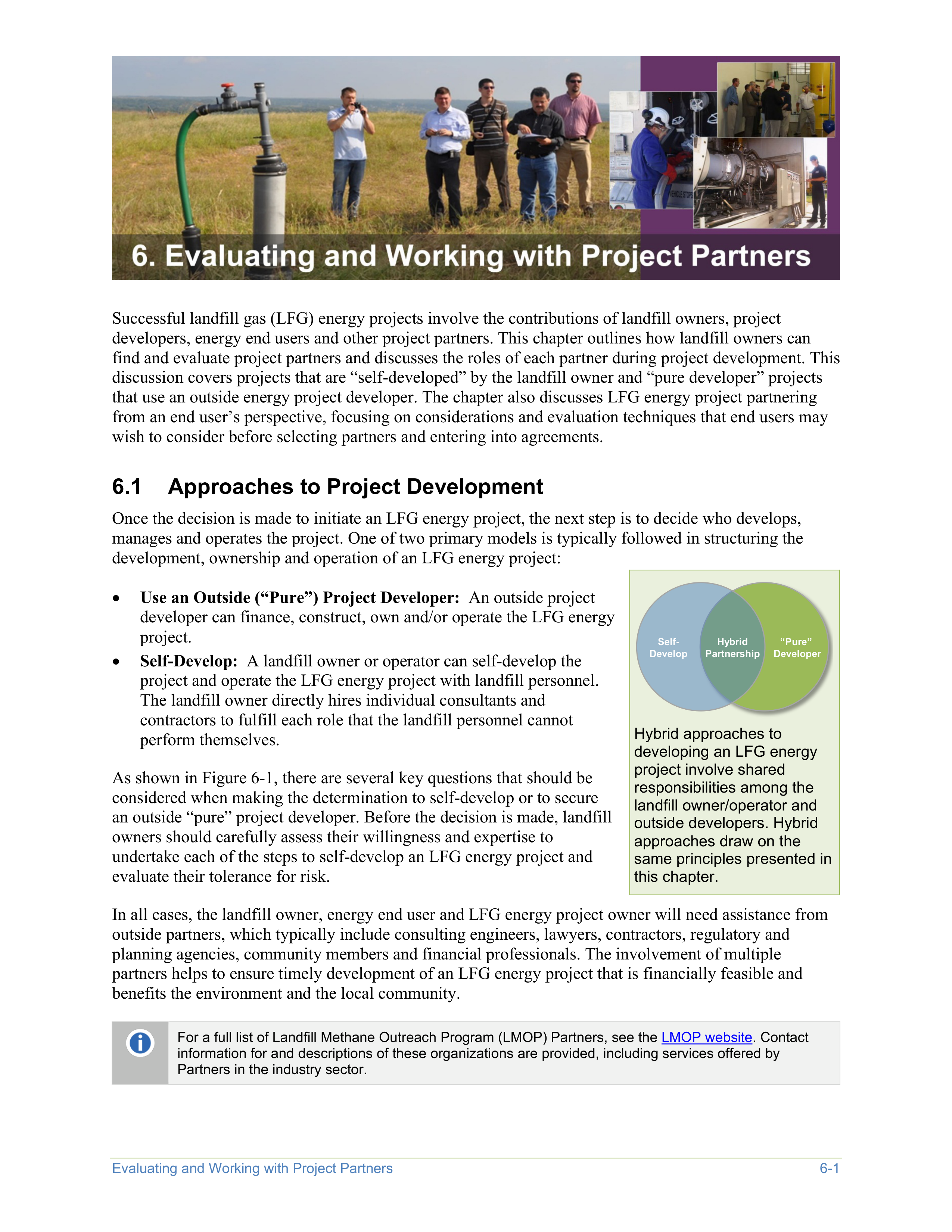


Evaluating and Working with Project Partners
6-1
Successful landfill gas (LFG) energy projects involve the contributions of landfill owners, project
developers, energy end users and other project partners. This chapter outlines how landfill owners can
find and evaluate project partners and discusses the roles of each partner during project development. This
discussion covers projects that are “self-developed” by the landfill owner and “pure developer” projects
that use an outside energy project developer. The chapter also discusses LFG energy project partnering
from an end user’s perspective, focusing on considerations and evaluation techniques that end users may
wish to consider before selecting partners and entering into agreements.
6.1
Approaches to Project Development
Once the decision is made to initiate an LFG energy project, the next step is to decide who develops,
manages and operates the project. One of two primary models is typically followed in structuring the
development, ownership and operation of an LFG energy project:
•
Use an Outside (“Pure”) Project Developer:
An outside project
developer can finance, construct, own and/or operate the LFG energy
project.
•
Self-Develop:
A landfill owner or operator can self-develop the
project and operate the LFG energy project with landfill personnel.
The landfill owner directly hires individual consultants and
contractors to fulfill each role that the landfill personnel cannot
perform themselves.
As shown in Figure 6-1, there are several key questions that should be
considered when making the determination to self-develop or to secure
an outside “pure” project developer. Before the decision is made, landfill
owners should carefully assess their willingness and expertise to
undertake each of the steps to self-develop an LFG energy project and
evaluate their tolerance for risk.
Self-
Develop
“Pure”
Developer
Hybrid
Partnership
Hybrid approaches to
developing an LFG energy
project involve shared
responsibilities among the
landfill owner/operator and
outside developers. Hybrid
approaches draw on the
same principles presented in
this chapter.
In all cases, the landfill owner, energy end user and LFG energy project owner will need assistance from
outside partners, which typically include consulting engineers, lawyers, contractors, regulatory and
planning agencies, community members and financial professionals. The involvement of multiple
partners helps to ensure timely development of an LFG energy project that is financially feasible and
benefits the environment and the local community.
For a full list of Landfill Methane Outreach Program (LMOP) Partners, see the
LMOP website
. Contact
information for and descriptions of these organizations are provided, including services offered by
Partners in the industry sector.
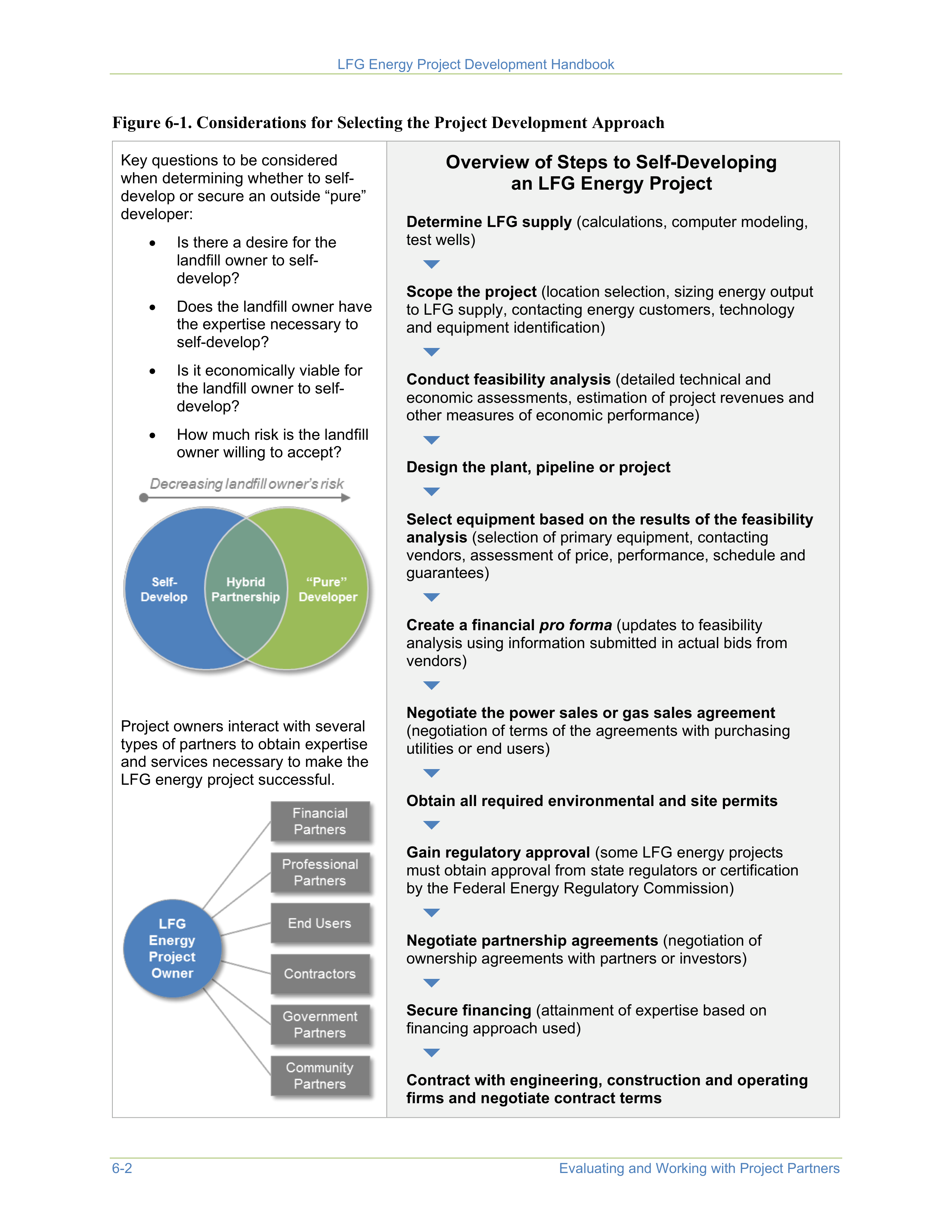
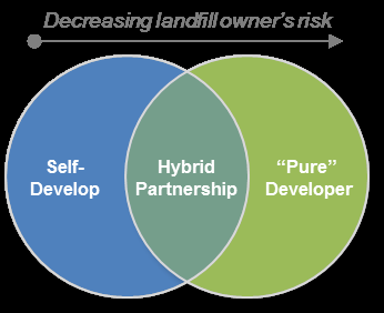
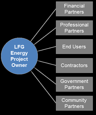
LFG Energy Project Development Handbook
6-2
Evaluating and Working with Project Partners
Figure 6-1. Considerations for Selecting the Project Development Approach
Key questions to be considered
when determining whether to self-
develop or secure an outside “pure”
developer:
•
Is there a desire for the
landfill owner to self-
develop?
•
Does the landfill owner have
the expertise necessary to
self-develop?
•
Is it economically viable for
the landfill owner to self-
develop?
•
How much risk is the landfill
owner willing to accept?
Project owners interact with several
types of partners to obtain expertise
and services necessary to make the
LFG energy project successful.
Overview of Steps to Self-Developing
an LFG Energy Project
Determine LFG supply
(calculations, computer modeling,
test wells)
Scope the project
(location selection, sizing energy output
to LFG supply, contacting energy customers, technology
and equipment identification)
Conduct feasibility analysis
(detailed technical and
economic assessments, estimation of project revenues and
other measures of economic performance)
Design the plant, pipeline or project
Select equipment based on the results of the feasibility
analysis
(selection of primary equipment, contacting
vendors, assessment of price, performance, schedule and
guarantees)
Create a financial
pro forma
(updates to feasibility
analysis using information submitted in actual bids from
vendors)
Negotiate the power sales or gas sales agreement
(negotiation of terms of the agreements with purchasing
utilities or end users)
Obtain all required environmental and site permits
Gain regulatory approval
(some LFG energy projects
must obtain approval from state regulators or certification
by the Federal Energy Regulatory Commission)
Negotiate partnership agreements
(negotiation of
ownership agreements with partners or investors)
Secure financing
(attainment of expertise based on
financing approach used)
Contract with engineering, construction and operating
firms and negotiate contract terms

LFG Energy Project Development Handbook
Evaluating and Working with Project Partners
6-3
Decision Factors
In deciding whether to seek a project developer, the landfill owner should consider economics, technical
expertise available to the landfill and the level of risk the landfill is willing to accept.
Economics
.
Significant capital (upfront) costs are required to design, build and operate an LFG energy
project. An economic feasibility study is prepared to determine whether the landfill owner has enough
capital available. Results of this study are evaluated for capital needs, internal rate of return (IRR) and
other financial needs. The landfill owner considers available capital and financing options (such as private
financing or municipal bonds) to determine whether sufficient funding is available or can be obtained. If
the landfill chooses to hire a developer, the developer would obtain the funding.
For more information about economic feasibility studies and financing, see
Chapter 4.
Expertise.
To develop an LFG energy project, landfill owners will need to interact with partners who
have a variety of specialized technical, financial or legal expertise. One way to improve this interaction is
to use a qualified project manager. A qualified project manager knows the landfill owner’s operating and
financial constraints, has the expertise and authority to direct work on the project and must be able to
make a significant time commitment to managing the project for a long period (often up to 2 years). If a
landfill owner does not have a project manager on staff, then they should consider contracting for an
outside project manager or hiring a project developer to perform this task.
Landfill owners might need to seek the expertise of consultants and contractors to design, build and
operate LFG energy projects, especially if they plan to self-develop. A consultant can give landfill owners
technical assistance on the design and technical recommendations regarding state and federal regulations
and operation of the wellfield and energy project. Contractors can provide advice on how to build the
LFG energy project, but their main responsibility is construction of the facility. After construction, a
contractor, operation and maintenance (O&M) vendor or consultant can operate the LFG energy project if
the landfill owner decides not to operate the project using landfill personnel.
Risk Level.
The amount of risk that the landfill owner is willing to accept is an important factor in
deciding whether to self-develop the LFG energy project or seek a project developer who will assume
much of the risk. Table 6-1 lists types of risks involved in LFG energy projects.
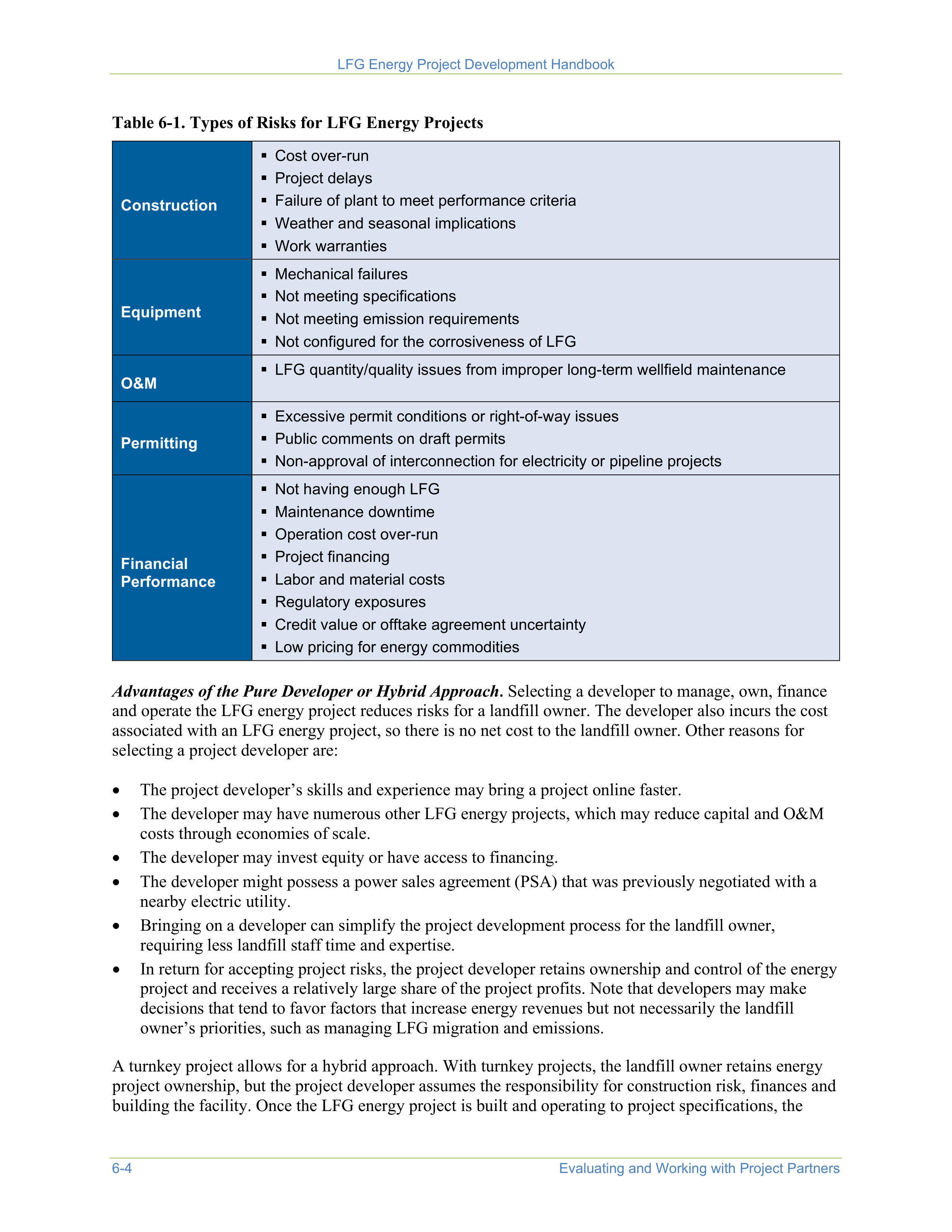
LFG Energy Project Development Handbook
6-4
Evaluating and Working with Project Partners
Table 6-1. Types of Risks for LFG Energy Projects
Construction
Cost over-run
Project delays
Failure of plant to meet performance criteria
Weather and seasonal implications
Work warranties
Equipment
Mechanical failures
Not meeting specifications
Not meeting emission requirements
Not configured for the corrosiveness of LFG
O&M
LFG quantity/quality issues from improper long-term wellfield maintenance
Permitting
Excessive permit conditions or right-of-way issues
Public comments on draft permits
Non-approval of interconnection for electricity or pipeline projects
Financial
Performance
Not having enough LFG
Maintenance downtime
Operation cost over-run
Project financing
Labor and material costs
Regulatory exposures
Credit value or offtake agreement uncertainty
Low pricing for energy commodities
Advantages of the Pure Developer or Hybrid Approach
.
Selecting a developer to manage, own, finance
and operate the LFG energy project reduces risks for a landfill owner. The developer also incurs the cost
associated with an LFG energy project, so there is no net cost to the landfill owner. Other reasons for
selecting a project developer are:
•
The project developer’s skills and experience may bring a project online faster.
•
The developer may have numerous other LFG energy projects, which may reduce capital and O&M
costs through economies of scale.
•
The developer may invest equity or have access to financing.
•
The developer might possess a power sales agreement (PSA) that was previously negotiated with a
nearby electric utility.
•
Bringing on a developer can simplify the project development process for the landfill owner,
requiring less landfill staff time and expertise.
•
In return for accepting project risks, the project developer retains ownership and control of the energy
project and receives a relatively large share of the project profits. Note that developers may make
decisions that tend to favor factors that increase energy revenues but not necessarily the landfill
owner’s priorities, such as managing LFG migration and emissions.
A turnkey project allows for a hybrid approach. With turnkey projects, the landfill owner retains energy
project ownership, but the project developer assumes the responsibility for construction risk, finances and
building the facility. Once the LFG energy project is built and operating to project specifications, the
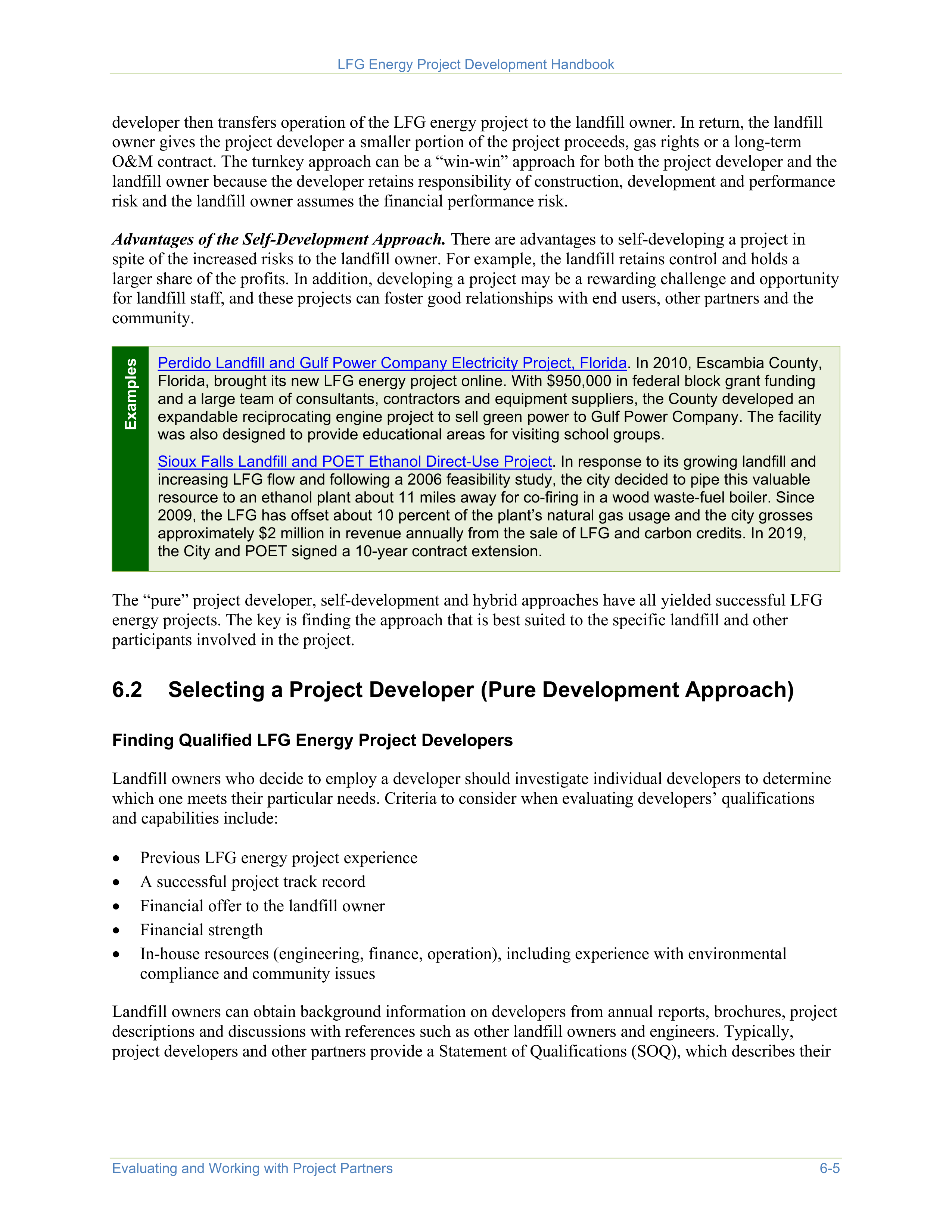
LFG Energy Project Development Handbook
Evaluating and Working with Project Partners
6-5
developer then transfers operation of the LFG energy project to the landfill owner. In return, the landfill
owner gives the project developer a smaller portion of the project proceeds, gas rights or a long-term
O&M contract. The turnkey approach can be a “win-win” approach for both the project developer and the
landfill owner because the developer retains responsibility of construction, development and performance
risk and the landfill owner assumes the financial performance risk.
Advantages of the Self-Development Approach.
There are advantages to self-developing a project in
spite of the increased risks to the landfill owner. For example, the landfill retains control and holds a
larger share of the profits. In addition, developing a project may be a rewarding challenge and opportunity
for landfill staff, and these projects can foster good relationships with end users, other partners and the
community.
Examples
Perdido Landfill and Gulf Power Company Electricity Project, Florida
. In 2010, Escambia County,
Florida, brought its new LFG energy project online. With $950,000 in federal block grant funding
and a large team of consultants, contractors and equipment suppliers, the County developed an
expandable reciprocating engine project to sell green power to Gulf Power Company. The facility
was also designed to provide educational areas for visiting school groups.
Sioux Falls Landfill and POET Ethanol Direct-Use Project
. In response to its growing landfill and
increasing LFG flow and following a 2006 feasibility study, the city decided to pipe this valuable
resource to an ethanol plant about 11 miles away for co-firing in a wood waste-fuel boiler. Since
2009, the LFG has offset about 10 percent of the plant’s natural gas usage and the city grosses
approximately $2 million in revenue annually from the sale of LFG and carbon credits. In 2019,
the City and POET signed a 10-year contract extension.
The “pure” project developer, self-development and hybrid approaches have all yielded successful LFG
energy projects. The key is finding the approach that is best suited to the specific landfill and other
participants involved in the project.
6.2
Selecting a Project Developer (Pure Development Approach)
Finding Qualified LFG Energy Project Developers
Landfill owners who decide to employ a developer should investigate individual developers to determine
which one meets their particular needs. Criteria to consider when evaluating developers’ qualifications
and capabilities include:
•
Previous LFG energy project experience
•
A successful project track record
•
Financial offer to the landfill owner
•
Financial strength
•
In-house resources (engineering, finance, operation), including experience with environmental
compliance and community issues
Landfill owners can obtain background information on developers from annual reports, brochures, project
descriptions and discussions with references such as other landfill owners and engineers. Typically,
project developers and other partners provide a Statement of Qualifications (SOQ), which describes their
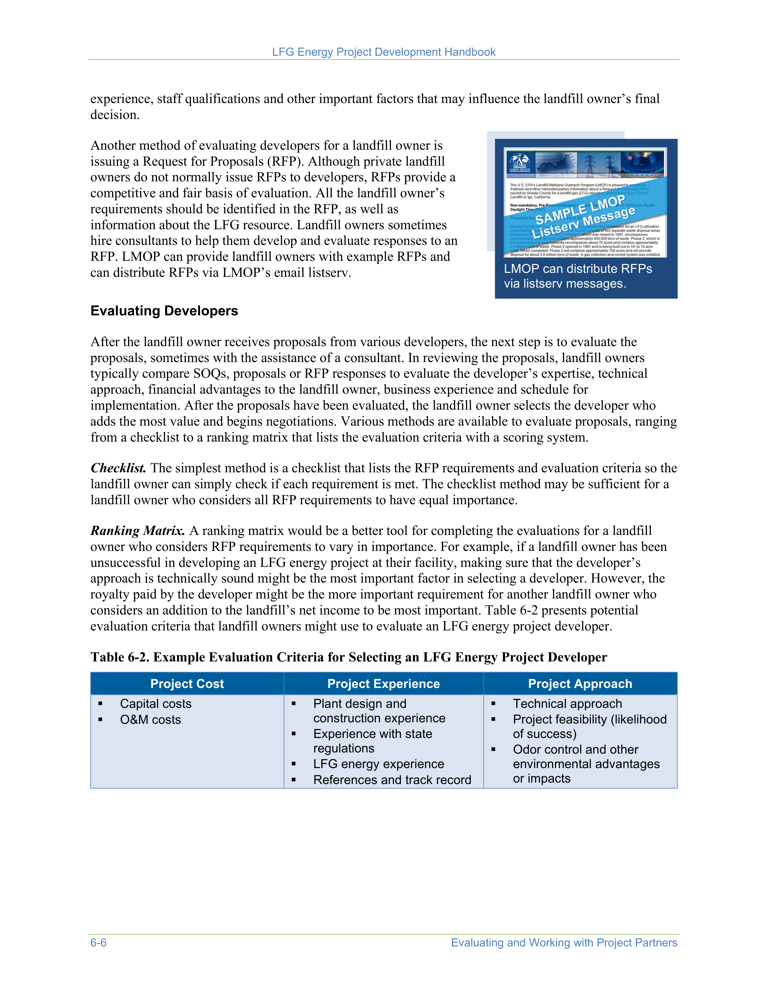


LFG Energy Project Development Handbook
6-6
Evaluating and Working with Project Partners
experience, staff qualifications and other important factors that may influence the landfill owner’s final
decision.
Another method of evaluating developers for a landfill owner is
issuing a Request for Proposals (RFP). Although private landfill
owners do not normally issue RFPs to developers, RFPs provide a
competitive and fair basis of evaluation. All the landfill owner’s
requirements should be identified in the RFP, as well as
information about the LFG resource. Landfill owners sometimes
hire consultants to help them develop and evaluate responses to an
RFP. LMOP can provide landfill owners with example RFPs and
can distribute RFPs via LMOP’s email listserv.
LMOP can distribute RFPs
via listserv messages.
Evaluating Developers
After the landfill owner receives proposals from various developers, the next step is to evaluate the
proposals, sometimes with the assistance of a consultant. In reviewing the proposals, landfill owners
typically compare SOQs, proposals or RFP responses to evaluate the developer’s expertise, technical
approach, financial advantages to the landfill owner, business experience and schedule for
implementation. After the proposals have been evaluated, the landfill owner selects the developer who
adds the most value and begins negotiations. Various methods are available to evaluate proposals, ranging
from a checklist to a ranking matrix that lists the evaluation criteria with a scoring system.
Checklist.
The simplest method is a checklist that lists the RFP requirements and evaluation criteria so the
landfill owner can simply check if each requirement is met. The checklist method may be sufficient for a
landfill owner who considers all RFP requirements to have equal importance.
Ranking Matrix.
A ranking matrix would be a better tool for completing the evaluations for a landfill
owner who considers RFP requirements to vary in importance. For example, if a landfill owner has been
unsuccessful in developing an LFG energy project at their facility, making sure that the developer’s
approach is technically sound might be the most important factor in selecting a developer. However, the
royalty paid by the developer might be the more important requirement for another landfill owner who
considers an addition to the landfill’s net income to be most important. Table 6-2 presents potential
evaluation criteria that landfill owners might use to evaluate an LFG energy project developer.
Table 6-2. Example Evaluation Criteria for Selecting an LFG Energy Project Developer
Project Cost
Project Experience
Project Approach
Capital costs
O&M costs
Plant design and
construction experience
Experience with state
regulations
LFG energy experience
References and track record
Technical approach
Project feasibility (likelihood
of success)
Odor control and other
environmental advantages
or impacts
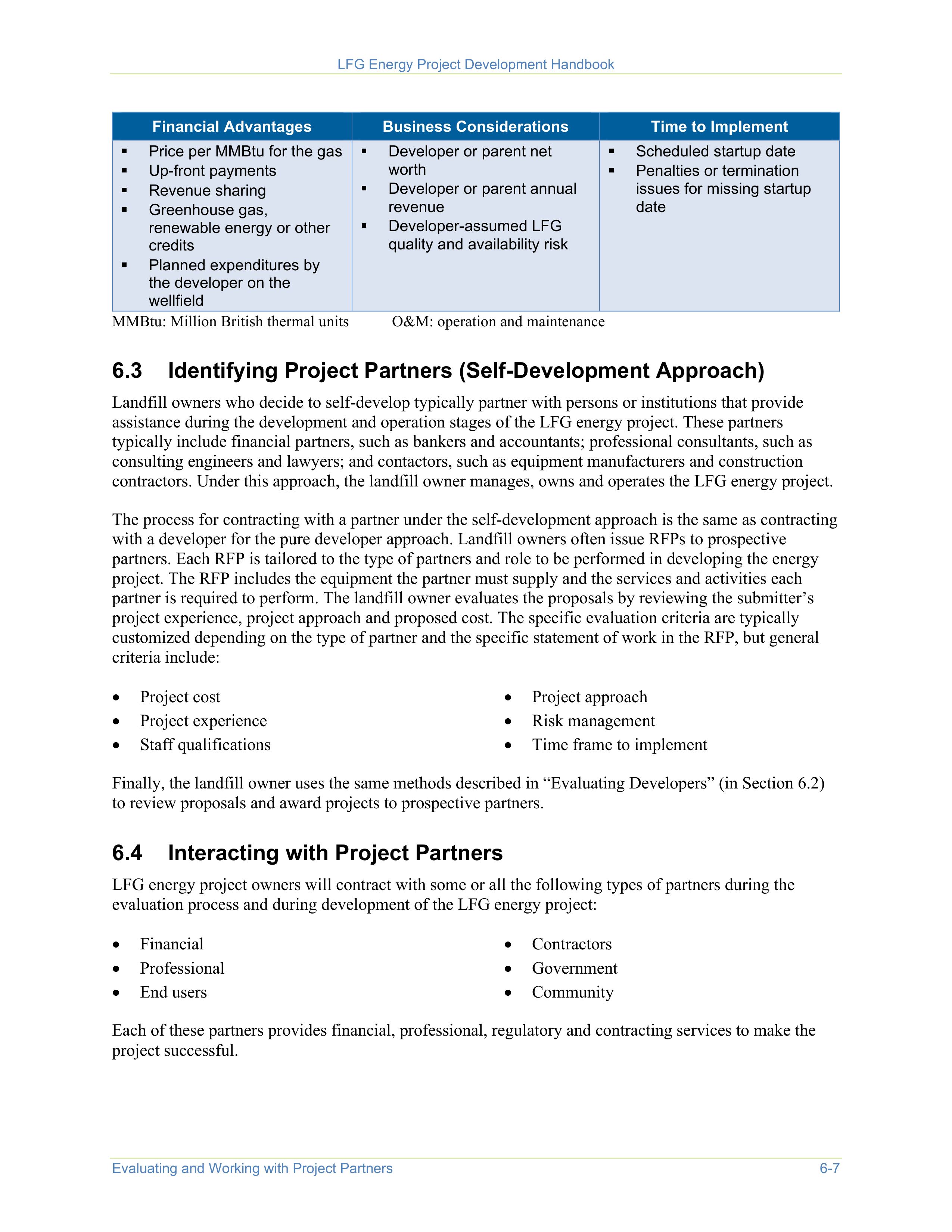
LFG Energy Project Development Handbook
Evaluating and Working with Project Partners
6-7
Financial Advantages
Business Considerations
Time to Implement
Price per MMBtu for the gas
Up-front payments
Revenue sharing
Greenhouse gas,
renewable energy or other
credits
Planned expenditures by
the developer on the
wellfield
Developer or parent net
worth
Developer or parent annual
revenue
Developer-assumed LFG
quality and availability risk
Scheduled startup date
Penalties or termination
issues for missing startup
date
MMBtu: Million British thermal units
O&M: operation and maintenance
6.3
Identifying Project Partners (Self-Development Approach)
Landfill owners who decide to self-develop typically partner with persons or institutions that provide
assistance during the development and operation stages of the LFG energy project. These partners
typically include financial partners, such as bankers and accountants; professional consultants, such as
consulting engineers and lawyers; and contactors, such as equipment manufacturers and construction
contractors. Under this approach, the landfill owner manages, owns and operates the LFG energy project.
The process for contracting with a partner under the self-development approach is the same as contracting
with a developer for the pure developer approach. Landfill owners often issue RFPs to prospective
partners. Each RFP is tailored to the type of partners and role to be performed in developing the energy
project. The RFP includes the equipment the partner must supply and the services and activities each
partner is required to perform. The landfill owner evaluates the proposals by reviewing the submitter’s
project experience, project approach and proposed cost. The specific evaluation criteria are typically
customized depending on the type of partner and the specific statement of work in the RFP, but general
criteria include:
•
Project cost
•
Project experience
•
Staff qualifications
•
Project approach
•
Risk management
•
Time frame to implement
Finally, the landfill owner uses the same methods described in “Evaluating Developers” (in Section 6.2)
to review proposals and award projects to prospective partners.
6.4
Interacting with Project Partners
LFG energy project owners will contract with some or all the following types of partners during the
evaluation process and during development of the LFG energy project:
•
Financial
•
Professional
•
End users
•
Contractors
•
Government
•
Community
Each of these partners provides financial, professional, regulatory and contracting services to make the
project successful.
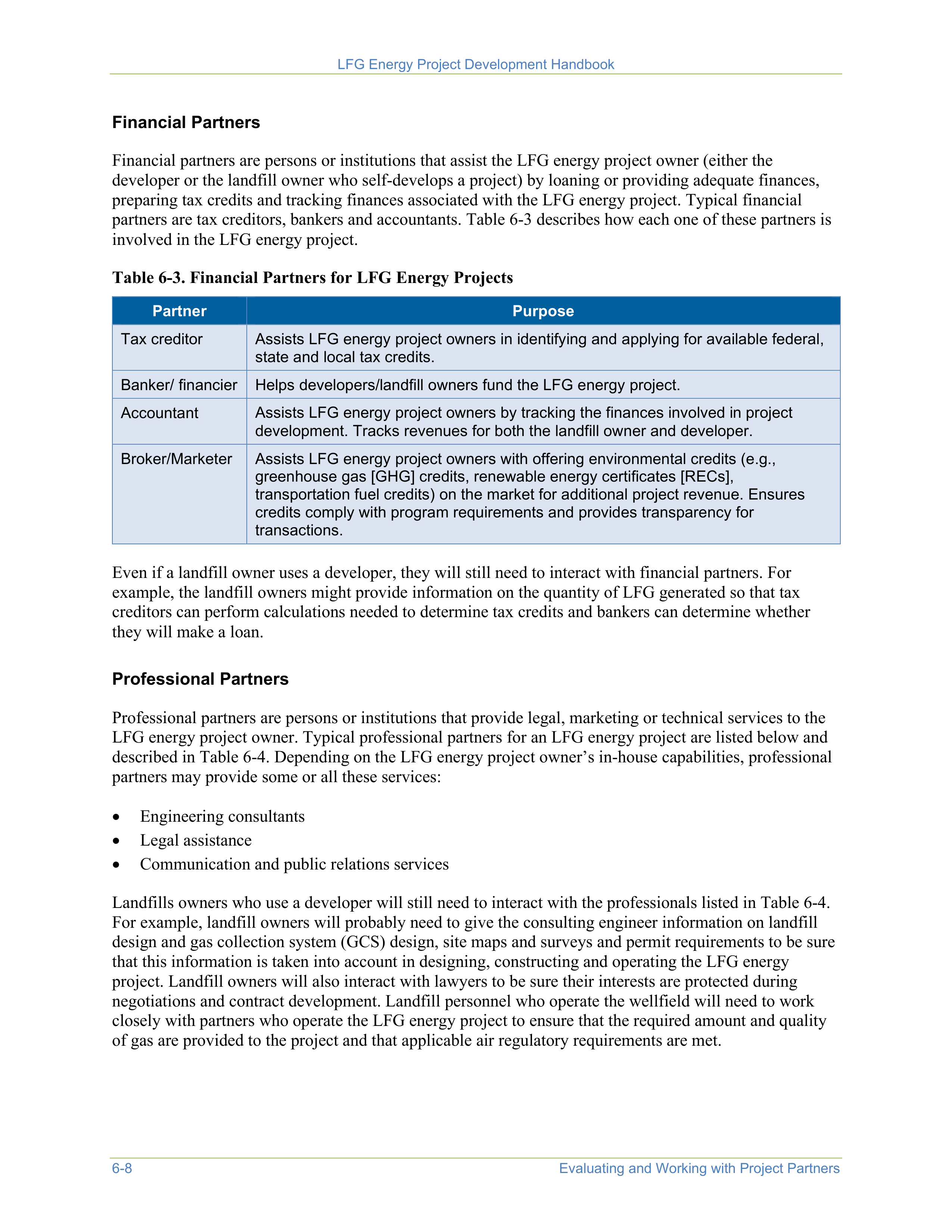
LFG Energy Project Development Handbook
6-8
Evaluating and Working with Project Partners
Financial Partners
Financial partners are persons or institutions that assist the LFG energy project owner (either the
developer or the landfill owner who self-develops a project) by loaning or providing adequate finances,
preparing tax credits and tracking finances associated with the LFG energy project. Typical financial
partners are tax creditors, bankers and accountants. Table 6-3 describes how each one of these partners is
involved in the LFG energy project.
Table 6-3. Financial Partners for LFG Energy Projects
Partner
Purpose
Tax creditor
Assists LFG energy project owners in identifying and applying for available federal,
state and local tax credits.
Banker/ financier
Helps developers/landfill owners fund the LFG energy project.
Accountant
Assists LFG energy project owners by tracking the finances involved in project
development. Tracks revenues for both the landfill owner and developer.
Broker/Marketer
Assists LFG energy project owners with offering environmental credits (e.g.,
greenhouse gas [GHG] credits, renewable energy certificates [RECs],
transportation fuel credits) on the market for additional project revenue. Ensures
credits comply with program requirements and provides transparency for
transactions.
Even if a landfill owner uses a developer, they will still need to interact with financial partners. For
example, the landfill owners might provide information on the quantity of LFG generated so that tax
creditors can perform calculations needed to determine tax credits and bankers can determine whether
they will make a loan.
Professional Partners
Professional partners are persons or institutions that provide legal, marketing or technical services to the
LFG energy project owner. Typical professional partners for an LFG energy project are listed below and
described in Table 6-4. Depending on the LFG energy project owner’s in-house capabilities, professional
partners may provide some or all these services:
•
Engineering consultants
•
Legal assistance
•
Communication and public relations services
Landfills owners who use a developer will still need to interact with the professionals listed in Table 6-4.
For example, landfill owners will probably need to give the consulting engineer information on landfill
design and gas collection system (GCS) design, site maps and surveys and permit requirements to be sure
that this information is taken into account in designing, constructing and operating the LFG energy
project. Landfill owners will also interact with lawyers to be sure their interests are protected during
negotiations and contract development. Landfill personnel who operate the wellfield will need to work
closely with partners who operate the LFG energy project to ensure that the required amount and quality
of gas are provided to the project and that applicable air regulatory requirements are met.
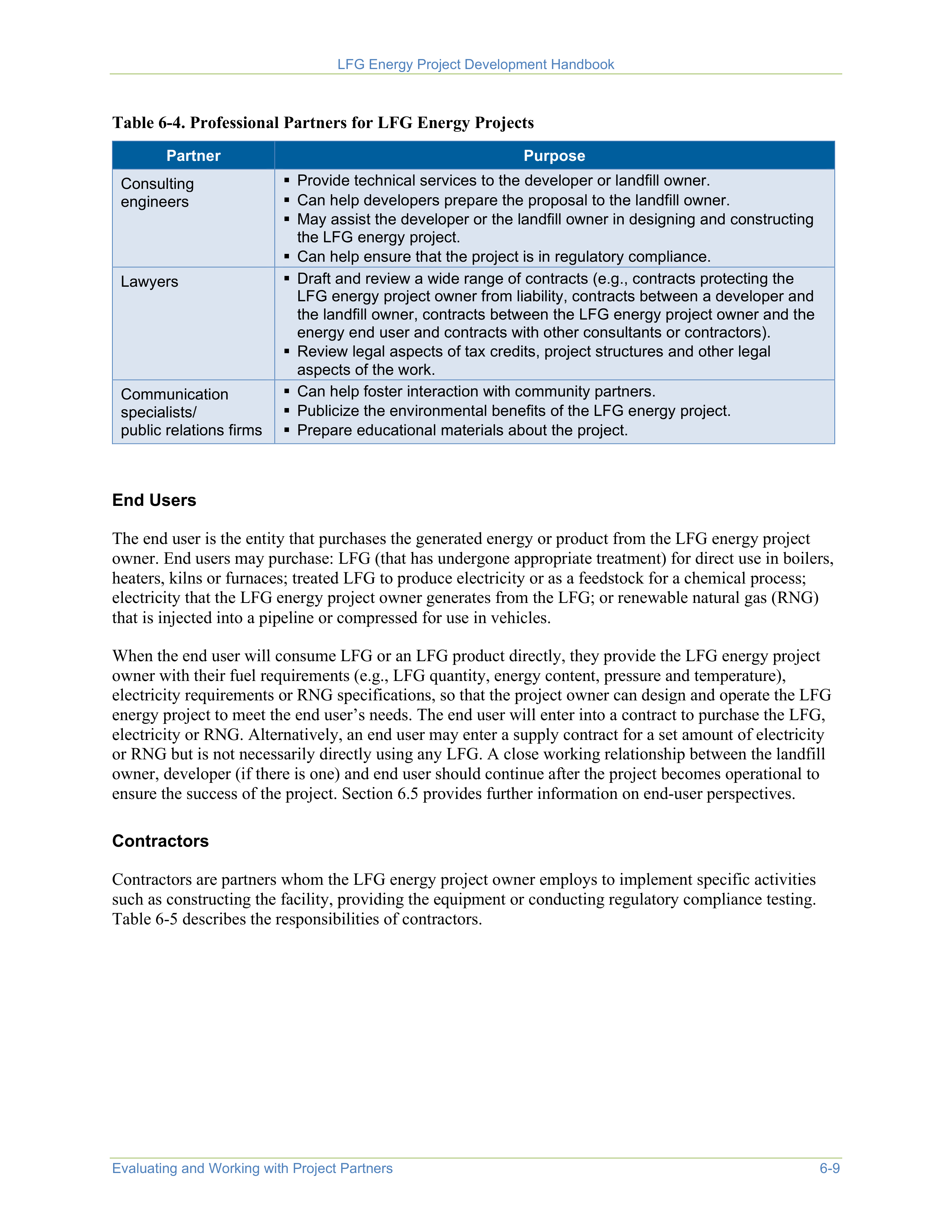
LFG Energy Project Development Handbook
Evaluating and Working with Project Partners
6-9
Table 6-4. Professional Partners for LFG Energy Projects
Partner
Purpose
Consulting
engineers
Provide technical services to the developer or landfill owner.
Can help developers prepare the proposal to the landfill owner.
May assist the developer or the landfill owner in designing and constructing
the LFG energy project.
Can help ensure that the project is in regulatory compliance.
Lawyers
Draft and review a wide range of contracts (e.g., contracts protecting the
LFG energy project owner from liability, contracts between a developer and
the landfill owner, contracts between the LFG energy project owner and the
energy end user and contracts with other consultants or contractors).
Review legal aspects of tax credits, project structures and other legal
aspects of the work.
Communication
specialists/
public relations firms
Can help foster interaction with community partners.
Publicize the environmental benefits of the LFG energy project.
Prepare educational materials about the project.
End Users
The end user is the entity that purchases the generated energy or product from the LFG energy project
owner. End users may purchase: LFG (that has undergone appropriate treatment) for direct use in boilers,
heaters, kilns or furnaces; treated LFG to produce electricity or as a feedstock for a chemical process;
electricity that the LFG energy project owner generates from the LFG; or renewable natural gas (RNG)
that is injected into a pipeline or compressed for use in vehicles.
When the end user will consume LFG or an LFG product directly, they provide the LFG energy project
owner with their fuel requirements (e.g., LFG quantity, energy content, pressure and temperature),
electricity requirements or RNG specifications, so that the project owner can design and operate the LFG
energy project to meet the end user’s needs. The end user will enter into a contract to purchase the LFG,
electricity or RNG. Alternatively, an end user may enter a supply contract for a set amount of electricity
or RNG but is not necessarily directly using any LFG. A close working relationship between the landfill
owner, developer (if there is one) and end user should continue after the project becomes operational to
ensure the success of the project. Section 6.5 provides further information on end-user perspectives.
Contractors
Contractors are partners whom the LFG energy project owner employs to implement specific activities
such as constructing the facility, providing the equipment or conducting regulatory compliance testing.
Table 6-5 describes the responsibilities of contractors.
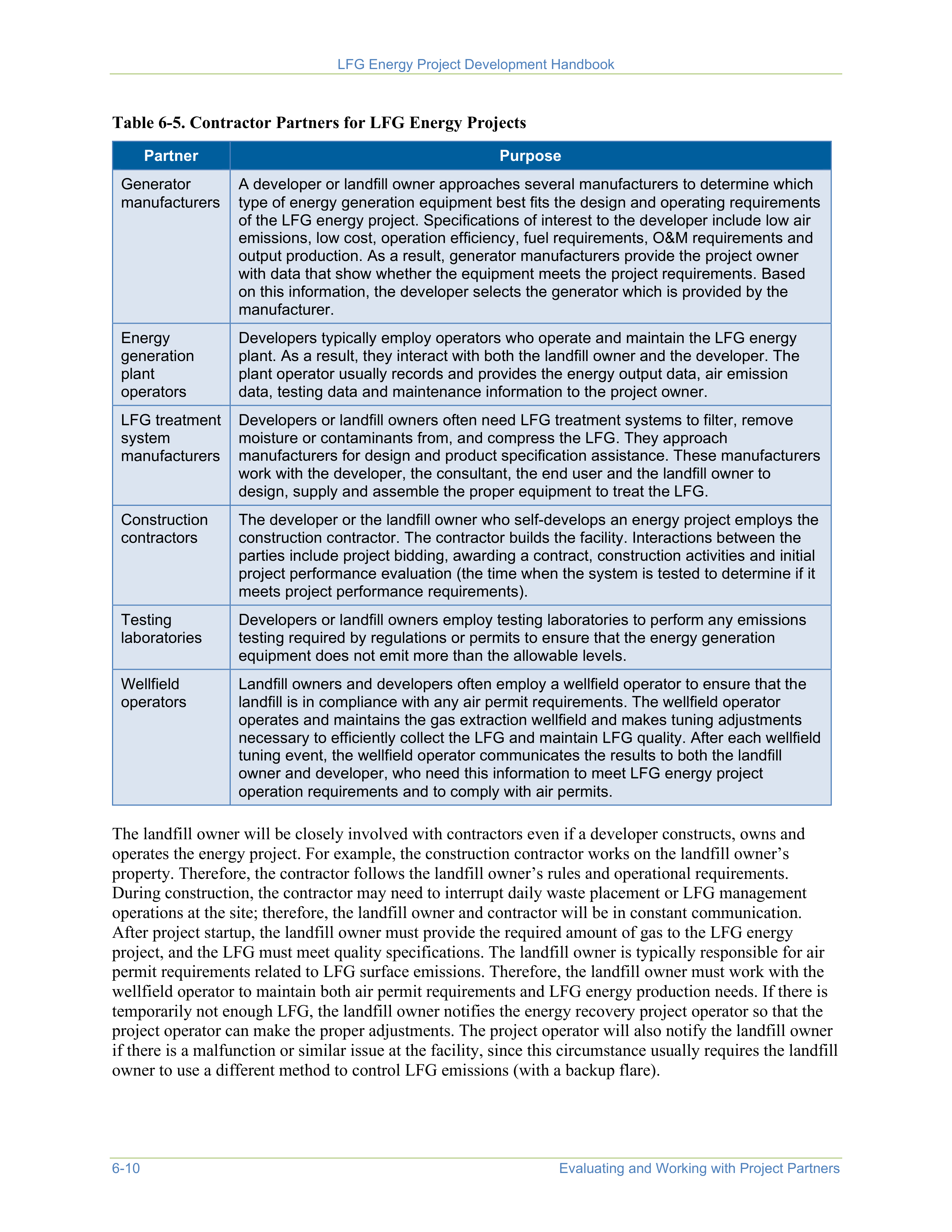
LFG Energy Project Development Handbook
6-10
Evaluating and Working with Project Partners
Table 6-5. Contractor Partners for LFG Energy Projects
Partner
Purpose
Generator
manufacturers
A developer or landfill owner approaches several manufacturers to determine which
type of energy generation equipment best fits the design and operating requirements
of the LFG energy project. Specifications of interest to the developer include low air
emissions, low cost, operation efficiency, fuel requirements, O&M requirements and
output production. As a result, generator manufacturers provide the project owner
with data that show whether the equipment meets the project requirements. Based
on this information, the developer selects the generator which is provided by the
manufacturer.
Energy
generation
plant
operators
Developers typically employ operators who operate and maintain the LFG energy
plant. As a result, they interact with both the landfill owner and the developer. The
plant operator usually records and provides the energy output data, air emission
data, testing data and maintenance information to the project owner.
LFG treatment
system
manufacturers
Developers or landfill owners often need LFG treatment systems to filter, remove
moisture or contaminants from, and compress the LFG. They approach
manufacturers for design and product specification assistance. These manufacturers
work with the developer, the consultant, the end user and the landfill owner to
design, supply and assemble the proper equipment to treat the LFG.
Construction
contractors
The developer or the landfill owner who self-develops an energy project employs the
construction contractor. The contractor builds the facility. Interactions between the
parties include project bidding, awarding a contract, construction activities and initial
project performance evaluation (the time when the system is tested to determine if it
meets project performance requirements).
Testing
laboratories
Developers or landfill owners employ testing laboratories to perform any emissions
testing required by regulations or permits to ensure that the energy generation
equipment does not emit more than the allowable levels.
Wellfield
operators
Landfill owners and developers often employ a wellfield operator to ensure that the
landfill is in compliance with any air permit requirements. The wellfield operator
operates and maintains the gas extraction wellfield and makes tuning adjustments
necessary to efficiently collect the LFG and maintain LFG quality. After each wellfield
tuning event, the wellfield operator communicates the results to both the landfill
owner and developer, who need this information to meet LFG energy project
operation requirements and to comply with air permits.
The landfill owner will be closely involved with contractors even if a developer constructs, owns and
operates the energy project. For example, the construction contractor works on the landfill owner’s
property. Therefore, the contractor follows the landfill owner’s rules and operational requirements.
During construction, the contractor may need to interrupt daily waste placement or LFG management
operations at the site; therefore, the landfill owner and contractor will be in constant communication.
After project startup, the landfill owner must provide the required amount of gas to the LFG energy
project, and the LFG must meet quality specifications. The landfill owner is typically responsible for air
permit requirements related to LFG surface emissions. Therefore, the landfill owner must work with the
wellfield operator to maintain both air permit requirements and LFG energy production needs. If there is
temporarily not enough LFG, the landfill owner notifies the energy recovery project operator so that the
project operator can make the proper adjustments. The project operator will also notify the landfill owner
if there is a malfunction or similar issue at the facility, since this circumstance usually requires the landfill
owner to use a different method to control LFG emissions (with a backup flare).
LFG Energy Project Development Handbook
Evaluating and Working with Project Partners
6-11
Government Partners
Regardless of whether the landfill owner chooses to hire a developer or to self-develop a project, the LFG
energy project owners will need to work with various governmental partners, including regulatory and
planning agencies.
Regulatory and Planning Agencies.
Regulatory partners
are involved to ensure that the project complies
with local, state and federal regulations. They are often the partners that “make or break” a project. As a
result, the LFG energy project owners and operators need to work closely with these partners to ensure
success.
Regulatory and planning agencies provide regulatory guidance and the required permits to landfill and
LFG energy project owners. When applications are prepared for zoning or land use permits, air permits
and conditional use permits, LFG energy landfill owners or developers engage with regulatory and
planning agency partners, such as:
•
State environmental regulatory agencies
•
State energy agencies, public utility
commissions
•
State or local air quality agencies or
departments
•
County board members
•
Local solid waste planning boards
•
Local economic development agencies
•
Local zoning and planning departments
These partners are involved primarily during the process of siting and permitting the facility. Discussions
between the LFG energy project owner and the regulatory agencies should begin early in the process to
ensure that LFG energy project owners understand all the environmental and land use requirements and
restrictions that will apply to the project and that the regulators’ concerns are satisfied. The project owner
will need to provide information showing that the project will meet emission limits and other
requirements and will need to demonstrate compliance once the project becomes operational. Each state
may have different regulations and procedures for these activities. Some of these regulations and
procedures can be found at the following websites:
•
LMOP’s State Agencies page
•
Database of State Incentives for Renewables and Efficiency (DSIRE)
State and local agencies can also play an active role in encouraging environmentally and economically
beneficial energy projects. LFG energy projects make use of a renewable energy resource, offset fossil
fuel combustion and may reduce odors and help improve local air quality. Projects can also create jobs
and other economic benefits for the community; in some cases, new businesses have located near a
landfill to use the gas, providing further economic benefits. In recognition of these benefits, many states
have created incentives for LFG energy and other renewable energy projects. Many state energy,
environmental protection and economic development agencies have partnered with LMOP to encourage
LFG energy projects in their states. These
LMOP State Partners
can assist landfills and end users who
want to develop projects.
Community Partners
Community partners are typically neighbors to the landfill, members of the public, local businesses and
environmental and community organizations. It is important for LFG energy project owners to provide
information to the community so that community partners understand how the LFG energy project might
affect them and to help the LFG energy project owner understand and address any community concerns.
LFG Energy Project Development Handbook
6-12
Evaluating and Working with Project Partners
Unless there is significant opposition to the LFG energy project, community partners are mainly involved
during the permitting process. LFG energy project designs should adhere to all local ordinances and
zoning, and the anticipated environmental and economic benefits to the surrounding community should be
clearly identified and communicated. When LFG energy project owners apply for the required permits
(air and zoning permits), community members provide comments during a public comment period.
During this public comment period, the community provides the LFG energy project owner or regulators
with questions, concerns or opposition to (or support for) the proposed facility. Depending on the results
of the public comment period, the permits are issued, modified or rejected.
LFG energy project owners can work with community organizations and the media to help the public
understand the benefits of an LFG energy project and to answer environmental, cost and other questions
that the community raises. Involving community groups in the planning of an LFG energy project can
help ensure that the type of LFG energy project chosen is a good fit for the community and provides
environmental and economic benefits to the community.
6.5
Evaluating Projects from an End User’s Perspective
LFG energy end users who make contractual agreements with the project owners or project developers
also have issues to consider before they enter into negotiations. End users should perform due diligence
on the prospective LFG energy project owner and evaluate several aspects of the proposed project,
including technical, financial and regulatory implications. End users may conduct their own research or
obtain professional services from consultants who specialize in performing due diligence. Potentially,
some end users may be working through a broker or fuel supplier, not directly with the project owner or
developer. In any of these scenarios, end users or their representatives typically consider the following
topics:
•
Quality and quantity of fuel
•
Reliability of fuel
•
Public perception
•
Time to develop the LFG energy project
•
Retrofits of combustion and other equipment necessary at the end user’s facility
•
Effect of LFG energy project on the end user’s air permit
•
Equipment maintenance (such as boilers, internal combustion engines and gas turbines)
•
Landfill owner and developer financial assurances
•
Contractual terms
Evaluating and Negotiating with Landfill Owners and Developers.
Evaluation begins with comparing
the results of due diligence studies with the end user’s requirements (financial goals, business objectives
and project schedule). If the proposed project meets the end user’s requirements, the end user begins
negotiating with the landfill owner or the LFG energy project owner, as appropriate, for purchasing the
LFG energy product. These negotiations may also involve lawyers, bankers, accountants and consultants.
If the end user finds a discrepancy with the project requirements, the end user discusses each discrepancy
with the landfill owner or developer. Depending on the degree of these discrepancies, the end user
negotiates a different price, requires the discrepancy to be addressed or proposes an alternative.
Evaluating Potential Partners.
End users engage in partnerships with consultants, financial professionals
and lawyers. Consultants provide technical recommendations to the end user about a range of project
issues, including environmental and regulatory compliance, economic
pro forma
analysis, LFG quantity
and quality, energy production and equipment operation and maintenance. Financial professionals can

LFG Energy Project Development Handbook
Evaluating and Working with Project Partners
6-13
include bankers, tax advisors and financial planners. They may provide finances necessary to purchase the
LFG, provide advice on obtaining tax credits or assist with financial planning. In addition, they help end
users obtain and receive grants, loans and credits. Lawyers provide legal advice to the end user about
LFG rights, contract agreements and site leases. Before entering into any contracts with project partners,
end users should assess potential partners by examining their past experience with LFG energy projects,
their project approaches, financial proposals and schedules. By working closely together throughout the
project development process, end users and their partners will help to ensure that the LFG energy project
produces environmental and economic benefits for the end user, the landfill owner and the community.

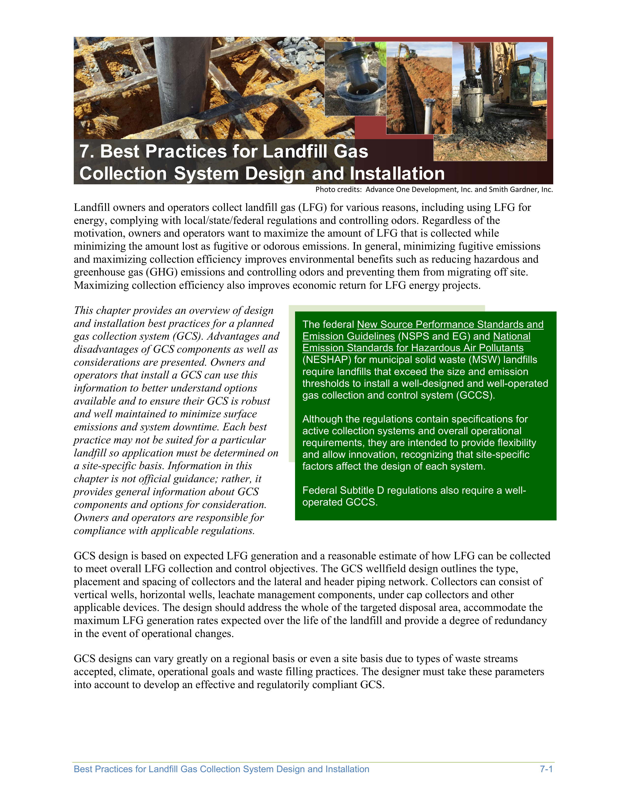
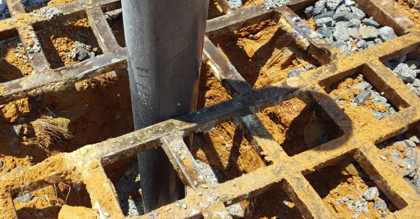
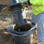
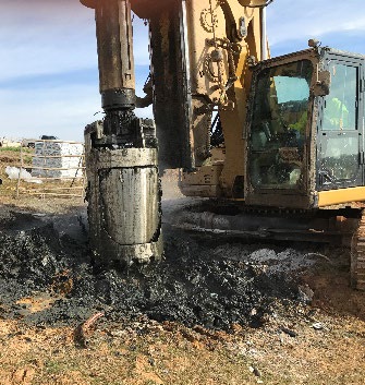
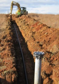


Best Practices for Landfill Gas Collection System Design and Installation
7-1
7. Best Practices for Landfill Gas
Collection System Design and Installation
Photo credits: Advance One Development, Inc. and Smith Gardner, Inc.
Landfill owners and operators collect landfill gas (LFG) for various reasons, including using LFG for
energy, complying with local/state/federal regulations and controlling odors. Regardless of the
motivation, owners and operators want to maximize the amount of LFG that is collected while
minimizing the amount lost as fugitive or odorous emissions. In general, minimizing fugitive emissions
and maximizing collection efficiency improves environmental benefits such as reducing hazardous and
greenhouse gas (GHG) emissions and controlling odors and preventing them from migrating off site.
Maximizing collection efficiency also improves economic return for LFG energy projects.
This chapter provides an overview of design
and installation best practices for a planned
gas collection system (GCS). Advantages and
disadvantages of GCS components as well as
considerations are presented. Owners and
operators that install a GCS can use this
information to better understand options
available and to ensure their GCS is robust
and well maintained to minimize surface
emissions and system downtime. Each best
practice may not be suited for a particular
landfill so application must be determined on
a site-specific basis. Information in this
chapter is not official guidance; rather, it
provides general information about GCS
components and options for consideration.
Owners and operators are responsible for
compliance with applicable regulations.
GCS design is based on expected LFG generation and a reasonable estimate of how LFG can be collected
to meet overall LFG collection and control objectives. The GCS wellfield design outlines the type,
placement and spacing of collectors and the lateral and header piping network. Collectors can consist of
vertical wells, horizontal wells, leachate management components, under cap collectors and other
applicable devices. The design should address the whole of the targeted disposal area, accommodate the
maximum LFG generation rates expected over the life of the landfill and provide a degree of redundancy
in the event of operational changes.
GCS designs can vary greatly on a regional basis or even a site basis due to types of waste streams
accepted, climate, operational goals and waste filling practices. The designer must take these parameters
into account to develop an effective and regulatorily compliant GCS.
The federal New Source Performance Standards and
Emission Guidelines (NSPS and EG) and National
Emission Standards for Hazardous Air Pollutants
(NESHAP) for municipal solid waste (MSW) landfills
require landfills that exceed the size and emission
thresholds to install a well-designed and well-operated
gas collection and control system (GCCS).
Although the regulations contain specifications for
active collection systems and overall operational
requirements, they are intended to provide flexibility
and allow innovation, recognizing that site-specific
factors affect the design of each system.
Federal Subtitle D regulations also require a well-
operated GCCS.
LFG Energy Project Development Handbook
7-2
Best Practices for Landfill Gas Collection System Design and Installation
7.1
Facility Review
Existing Site Conditions
Site conditions and operational goals both influence the design of a GCS. Site conditions such as landfill
geometry, moisture, compaction rates, waste types, waste depths, cover soils permeability and final cover
all affect GCS design. The greater the moisture within the waste mass, the faster LFG will be generated
and the higher the peak LFG generation rate. A more rapid LFG generation rate also leads to a waste mass
that tends to settle faster, which may cause damage to collectors that may need to be assessed and
potentially replaced. Liquids within the waste mass may decrease the pore space within the waste mass,
decreasing the ability of LFG to move to the LFG extraction wells. Thus, landfills with higher moisture
content may have a smaller effective radius (or zone) of influence for individual collectors and may
require more collectors for the same area of coverage. Conversely, some sites choose to add moisture to
promote decomposition, which increases LFG generation but may increase GCS operational costs due to
additional wells, increased settlement and larger header sizing.
Physical properties of the waste mass such as waste density (compaction), type and depth vary by site and
affect the moisture level and methane generation potential of the landfill. Many sites accept special waste
streams such as sludges, ash, construction and demolition (C&D) and liquids, which greatly affect the
GCS design, gas generation rates and the suitability of the LFG for beneficial use. For example, gypsum
wall board and onions are known to elevate hydrogen sulfide (H
2
S) within LFG, which may need to be
removed.
The materials used for daily, intermediate and final cover also vary depending on local availability of
soils, climate and approvals for alternate cover materials. Daily cover prevents blowing litter and odors
and is usually not considered part of the GCS design. Sites that use a low-permeability soil such as clay
for daily and intermediate cover can greatly reduce the influence of the LFG collectors and the
effectiveness of the GCS. If this low-permeability soil cover is not completely stripped between
placement of waste lifts, the waste mass can be isolated from other landfill components, which negatively
affects the ability to collect LFG and drain leachate. It also increases the likelihood of LFG emissions and
perched leachate (pooling of leachate on top of an impermeable layer) within the waste mass.
At the landfill surface, intermediate and final cover are designed to provide a seal between the landfill and
the atmosphere. A more impermeable seal on the surface of the landfill allows more vacuum to be applied
to LFG collectors while minimizing the potential for atmospheric air and water to seep into the waste
mass and ultimately into the LFG collectors. The more impermeable the intermediate and final cover, the
greater the potential well spacing and the better the LFG wells are likely to operate.
Climate
GCS design can vary greatly due to local climatic conditions. The two most critical elements are
temperature and the precipitation. Accounting for temperature involves considering how GCS
components will respond both during typical and extreme weather events. For example, sites in areas that
experience extended temperatures below 0
o
C (32
o
F) require freeze protection on equipment and vessels,
and all header pipes and laterals should be buried to prevent freezing. Alternately, sites in very warm,
sunny areas can have exposed GCS components experience significant thermal movement as they expand
during the day and then contract overnight.
Precipitation leads to additional liquids within the landfill. It enters the waste mass through the working
face or via percolation through the various cover layers. Landfills in areas of high precipitation should
LFG Energy Project Development Handbook
Best Practices for Landfill Gas Collection System Design and Installation
7-3
limit liquids entering the landfill because it can affect LFG generation and/or operation of the GCS.
Precipitation can also be a major operating hazard as GCS components can become inaccessible on steep
slopes if the surface is too wet or following significant snow fall events. Sites in areas of low precipitation
must also consider design and operation. Low precipitation sites experience lower LFG flows, greater
areas of influence for the LFG collectors and greater desiccation of the soils that make up the cover,
making them more permeable. This often prevents landfills located in very dry climates from producing
significant quantities of LFG.
Operational Goals
A GCS is typically designed and operated to collect as much LFG as possible to prevent fugitive
emissions and/or maximize collection for beneficial use. Depending on which of these goals is
emphasized, the direction of the GCS design and operation could vary. This, coupled with financial
impacts from GCS installation and operation, may require a careful balancing of goals and costs as it
relates to GCS design, installation and operation.
Each landfill has one or more key operational goals. Below are some of the most common goals and
measures landfill owners and operators take to achieve goals.
Maintain Compliance
.
Landfills that operate a GCS only to maintain compliance with federal, state
and/or local requirements are mainly concerned with capturing the gas, controlling gas migration and
minimizing fugitive emissions and odors. These sites focus on maximizing collection, however, this often
leads to a slight over pull of vacuum on the LFG collectors where atmospheric air intrudes into the
collector typically through the cover. The over pull (ambient air intrusion) results in higher concentrations
of nitrogen or oxygen in the LFG than would occur otherwise. Provided oxygen levels are maintained
below the levels that might lead to a subsurface oxidation event, specific LFG composition percentages
are of less importance at a landfill with the goal of compliance.
To control costs, systems operating for compliance can often be implemented with relatively less dense
well spacing and therefore fewer wells, while applying a slightly greater vacuum to achieve a larger
radius of influence.
Electricity Generation
.
Landfills that use LFG for electricity generation are concerned with extracting
sufficient LFG to operate the electricity generation equipment at full capacity. Unlike sites operating for
compliance, sites that are using LFG for electricity generation are concerned with LFG composition.
Oxygen at a low level is not an issue for electricity generation equipment but oxygen in sufficiently large
quantities can be extremely harmful to the equipment. To control oxygen content and related costs for
electricity generation, systems for electricity generation are often implemented with a slightly tighter well
spacing (i.e., denser spacing, more wells) than a GCS designed for compliance alone. This allows an
electricity generation project’s GCS to achieve the collection of LFG with limited over pull.
Medium-Btu Gas Production
.
Because LFG contains about 50 percent methane, it has about half the
energy content of natural gas. Therefore, projects that minimally treat LFG for use as a replacement for
fossil fuel are often called “medium-Btu” projects (Btu is British thermal unit). Medium-Btu LFG end
uses include a wide range of technologies such as boilers, greenhouses, kilns, dryers and heaters. GCS
owners or operators that produce medium-Btu gas are mainly concerned with extracting sufficient LFG to
meet the needs of the downstream gas user. Because LFG generally requires minimal conditioning for use
as a medium-Btu gas, these systems’ operations largely depend on the end user’s fuel requirements.
Renewable Natural Gas Production
.
Landfills that recover LFG for production of renewable natural gas
(RNG) focus on extracting sufficient LFG to operate the RNG equipment at full capacity with as few
LFG Energy Project Development Handbook
7-4
Best Practices for Landfill Gas Collection System Design and Installation
treatment steps as possible. Unlike sites operating for compliance or electricity generation, sites that are
upgrading LFG to RNG are much more concerned about LFG composition. Oxygen and nitrogen at high
quantities can be extremely difficult and costly to remove. To control LFG composition and minimize
costs for the RNG equipment, these systems are often implemented with significantly tighter well spacing
(i.e., denser spacing, more wells) than a GCS for electricity generation or compliance. This allows the
RNG project’s GCS to collect LFG with limited oxygen or nitrogen resulting from over pull.
Waste Acceptance and Filling Practices
Landfill intake rates, waste composition and working face practices can greatly affect the design of a
GCS. Landfills with higher acceptance rates typically generate more LFG and have more settlement of the
waste mass, which can negatively affect the GCS components. To ensure the GCS continues to operate, a
more frequent replacement plan and schedule are often required for wells, piping and other GCS
components at the design stage.
Installation Schedule
The installation and operation of GCS components is often driven in large part by regulatory
requirements. The federal NSPS and EG have defined schedules for GCS installation and expansion
based on landfill size and emissions. In some cases, it may be advantageous for the landfill
owner/operator to install a GCS prior to being required under regulatory criteria. Benefits may include:
•
Control of operational odors
•
Additional fuel or beneficial use
•
Reduction in emissions.
“Early” LFG collection can be implemented within a few months of waste placement, depending on the
configuration of the fill area and the rate of waste decomposition, and can be accomplished through a
range of techniques and components, including:
•
Vertical wells
•
Horizontal collectors
•
Caisson wells
•
Connections to the leachate collection system.
These components are discussed in the following section and should be evaluated for each GCS based
upon the specific need of that landfill, the configuration of the fill area, rate of waste placement and any
operational concerns that may be present.
7.2
LFG Collectors
Once the review of the landfill is complete, design of the GCS can begin. One of the key components of
the GCS is the LFG collectors. LFG collectors are typically composed of slotted or perforated plastic
pipe, surrounded by stone or other aggregate backfill material, that are installed in borings (for vertical
configurations) or trenches (for horizontal configurations) in the waste mass, below the surface of the
landfill. Design considerations for both vertical and horizontal wells, as well as other early collector
techniques, are discussed below.
LFG Energy Project Development Handbook
Best Practices for Landfill Gas Collection System Design and Installation
7-5
The GCS is not an isolated system and can be affected by other operations within the landfill. For
example, proper maintenance and operation of the leachate collection system is critical to the operation of
LFG collectors, by keeping the waste mass relatively free draining and allowing LFG to flow through the
waste mass and into the LFG collector. Failure to maintain leachate collection system operation can lead
to diminished operation of the GCS, regardless of the type of extraction well(s) employed
.
Vertical Extraction Wells
As discussed in
Chapter 1
, vertical wells are the most common well type due to their ability to be
installed across most landfill areas and effectively operated to meet a variety of GCS operational goals.
Vertical wells have the advantage of being capable of operation as soon as they are installed and being
more effective at controlling surface emissions than horizontal collectors. Vertical wells can also be
adjusted or “tuned” to accommodate a wide range of operational requirements, including compliance and
various utilization goals and to supplement liquids removal. One downside is the need for operators to
continue compacting waste around vertical wells installed in operational areas of the landfill and the need
to extend or re-drill the wells as waste placement progresses.
The components of a vertical well include the borehole, well casing, backfill materials and well seal.
Boreholes.
Vertical well boreholes typically range from 24 inches to 36 inches in diameter. Larger
diameter boreholes increase the surface area of the well perimeter, which in turn can increase LFG
collection. Larger boreholes also allow additional space for gravel backfill, which can prevent adjacent
waste fines from clogging the well casing perforations. Borings less than 24 inches in diameter are
generally discouraged as they provide less filter between the waste mass and the well casing and may
necessitate the use of smaller well casings. Smaller casings have a reduced structural integrity and limit
the ability to remove liquids from the extraction well.
The depth of the boreholes should be based on a reliable source of bottom liner elevation data such as an
as-built survey. The as-built survey should be certified by a Registered Land Surveyor or Professional
Engineer, and should identify the depth to any geosynthetic components and the elevation top of clay or
the top of protective leachate collection media. With modern computer technology, many as-built surveys
are now contained in a three-dimensional digital file that allow the user to identify the liner component
relatively accurately. The well’s depth should ultimately be no closer than 15 feet to the liner to avoid
damaging the liner system. However, if no as-built survey is available, then the buffer should be increased
based on known information.
It is critical to generate an accurate survey of the proposed boring location and compare it to known areas
of waste deposition (including wet waste, asbestos, other “special” wastes, C&D debris) and previously-
constructed GCS components. Impacting any of these items results in varied levels of construction and/or
operational concern.
Borehole depths typically range from 40 to 140 feet below the surface of the landfill, but depths can be
greater in quarries and canyon fills. The maximum depth achievable is usually limited by the drilling
equipment. There are several challenges associated with very deep boreholes, including:
•
Vacuum dispersion
•
Well integrity (due to higher potential of settlement or crushing)
•
High waste compaction, which decreases the waste permeability and inhibits LFG extraction
•
High degree of decomposition, which can potentially lead to saturated wastes, borehole collapse and
limited LFG extraction.
LFG Energy Project Development Handbook
7-6
Best Practices for Landfill Gas Collection System Design and Installation
Well Casing.
Vertical well casings typically range from 4- to 8-inch diameter pipe. In addition to
collecting more LFG, a larger diameter well casing can decrease the potential for crushing and pinching
of the well. Well casing diameters of at least 4 inches can also accommodate retroactive installation of
pumps in areas that may require future dewatering.
Vertical well casings are typically constructed of polyvinyl chloride (PVC) or high-density polyethylene
(HDPE). In some landfills with elevated temperatures, chlorinated polyvinyl chloride (CPVC) pipe or
stainless steel is used for their ability to withstand higher temperatures. Table 7-1 presents considerations
for selecting the casing material.
Table 7-1. Well Casing Material Design Considerations
Design
Consideration
PVC Pipe
HDPE Pipe
Material
Properties
Most suitable for vertical well casing
construction due to its strength and
temperature resistance. Differential
settlement of the waste mass may lead to
brittle fracture of the casing, allowing
some degree of gas flow through the
fracture.
Better suited for horizontal well casing and
header and lateral pipe applications due to its
flexibility and resistance to crushing. Often used
in vertical wells since the piping will deform and
bend with settlement. However, severe
settlement may pinch the pipe and seal it off,
inhibiting LFG flow.
Material rigidity is susceptible to breaking
by heavy equipment; however, field
observations have also shown that broken
PVC material can still act as a gas
conduit.
Does not serve as a gas conduit when pinched.
Resistant to pinching, elongation and
deformation of perforations/slots;
however, more vulnerable to ultraviolet
radiation and brittleness from low
temperatures.
Flexible and able to withstand the inherent
shifting of a waste mass; due to the flexible
properties of HDPE, perforations/slots are
discouraged.
Installation
Fabricated as it is lowered into place; PVC
sections, including extensions, are
connected via threads or via slip
couplings, screws and glue.
Fabricated prior to installation using specialized
equipment and trained technicians to fuse
sections together.
Temperature
Better suited for high gas temperatures
<82˚C (180˚F).
Not recommended for long-term service above
60˚C (140˚F).
Cost
Price has remained relatively stable
between 2013 and 2018.
Price fluctuates based on petroleum market
rates. In 2018, approximately 25 percent higher
cost than comparable PVC casing.
In addition to selecting the type of material, the appropriate specification of the pipe, including wall
thickness (e.g., Schedule 80 PVC, Standard diameter ratio (SDR) 11 HDPE), resin blend and joining
methods are also important to ensure the longevity of the system.
1
1
California Integrated Waste Management Board. Technologies and Management Options for Reducing Greenhouse Gas
Emissions From Landfills. April 2008.
https://www2.calrecycle.ca.gov/Publications/Details/1268
.
The lower portion of the casing material is perforated with holes or slots to collect LFG from the
surrounding area. The casing design should ensure that perforations are not too close to the surface to
LFG Energy Project Development Handbook
Best Practices for Landfill Gas Collection System Design and Installation
7-7
avoid air intrusion.
2
In addition, the design should consider if the well will need to be able to
accommodate a pump to extract liquids at the time of construction, or potentially be added later. Wells
with pumps are often called dual extraction wells for their ability to extract LFG and liquids.
2
British Columbia Ministry of Environment. Landfill Gas Management Facilities Design Guidelines. March 2010.
https://www2.gov.bc.ca/assets/gov/environment/waste-management/garbage/designguidelinesfinal.pdf
.
The casing design should specify the spacing and diameter of the perforations both in terms of size and
frequency. The specification is typically based on the total square inches of perforations per linear foot of
casing to maintain the integrity of the casing material. The U.S. Army Corps of Engineers recommends
perforations of 0.5-inch diameter holes spaced at 90 degree angles every 6 to 12 inches or a minimum of
0.1-inch slots.
3
Current industry practice utilizes slots of approximately 3/8-inch width to reduce the
potential for clogging. The specification of the perforations needs to be coordinated with the backfill
around the casing so that the perforations do not permit the stone surrounding the well to enter the casing.
Perforation slots can be cut at the landfill, but it is generally more cost-effective to order the pipe
fabricated directly from the supplier using tooling purposely designed for this application. If HDPE is
used for the casing material, slots are discouraged because the flexible properties of this material can
cause the slots to heal over (i.e., close on themselves) at higher temperatures.
3
U.S. Army Corps of Engineers. Landfill Gas Collection and Treatment Systems Engineer Manual. April 2013.
http://www.publications.usace.army.mil/Portals/76/Publications/EngineerManuals/EM_200-1-22.pdf?ver=2013-09-05-
152155-217
.
The upper portion of the casing is not perforated and should consist of the same size and type of pipe
material as the lower, perforated section. The solid portion of the casing should extend approximately 15
to 20 feet below the landfill surface. The depth of solid pipe should be selected in part by considering how
much atmospheric air is acceptable to pull into the well. The greater the length of solid pipe, the less
amount of air that is likely to be pulled into the well. The well casing should extend a few feet above the
ground surface, to provide a visual location for the well and to allow a wellfield technician to monitor,
adjust (i.e., tune) and service the well. The casing’s exact height above the surface should be determined
based on operating and fill practices at the landfill.
The backfill around the well casing is a granular material that allows LFG to enter the perforated portion
of the well casing. The granular material, typically gravel or a similar material, is placed around the
perforated section of the casing pipe, completely filling the annular space of the borehole. The granular
backfill provides lateral strength to the casing to minimize the risk of it being crushed from movement of
the surrounding waste due to compaction or settlement. Granular backfill also allows the LFG to move
freely from the waste into the well casing and acts as a filter to prevent waste materials from entering the
casing. Several factors should be considered when selecting the granular backfill material, including:
•
The size of the material should be large enough to act as filter but small enough to not bridge (lodge
together and block flow) when being placed. The uniformity of the gradation and the amount of fines
(very small particles) should also be considered. The gradation needs to be coordinated with
perforated casing.
•
Stone should be washed to minimize clogging of the well from dust and fine particles.
•
The type of granular material depends on availability and cost but materials that are incompatible
with landfill liquids (e.g., carbonate rock such as limestone or cement-based stone) should be
avoided.
•
Low-carbonate content stone minimizes reaction with landfill liquids, which can contribute to scaling
and clogging of the perforations.
•
Rounded aggregate, such as pea gravel and river rock, is an ideal material if readily available.
LFG Energy Project Development Handbook
7-8
Best Practices for Landfill Gas Collection System Design and Installation
•
Manmade materials such as tire chips, glass cullet and other waste materials can be used as the
granular material in some situations.
Well Seal.
The well seal is a plug around the casing where it emerges from the waste and cover material
to prevent air and liquids from entering the well from the atmosphere. The amount of vacuum that can be
applied to a collector, as well as the overall performance of the GCS, can be limited by the effectiveness
of the seal. Several methods or materials are available to ensure a tight well seal, including those listed
below. Figure 7-1 shows the installation of bentonite and foam sealants.
Bentonite. Bentonite is a family of clay compounds that expands when wet to serve as an effective seal.
4
A bentonite seal is typically 3 to 4 feet thick and is placed on top of the granular backfill of the collector.
5
This seal minimizes infiltration of air from the surface into the collector. For the seal to be effective, it is
imperative that the bentonite is sufficiently hydrated during placement. High-swelling materials such as
bentonite shrink on dehydration and reduce the effectiveness of the seal and allow air intrusion. Soils over
the bentonite seal help keep the moisture within the seal and can decrease the likelihood of the seal
desiccating and cracking. For dry sites, a non-bentonite material such as expandable foam or compacted
soil should be considered.
4
U.S. EPA, Office of Solid Waste and Emergency Response (5306W). EPA 530-F-97-002. 7/97. Geosynthetic Liners Used in
MSW Landfills.
5
U.S. Army Corps of Engineers. Landfill Gas Collection and Treatment Systems Engineer Manual. April 2013.
http://www.publications.usace.army.mil/Portals/76/Publications/EngineerManuals/EM_200-1-22.pdf?ver=2013-09-05-
152155-217
.
Bentonite Slurry. Many landfills use a bentonite slurry to enhance the seal around the collector. When
applied around the penetration, the slurry fills the voids that may remain. Hydration is much more
thorough and consistent compared to in situ hydration of dry bentonite.
Foam Plug. Generally available as a two-part mix, the foam is mixed at the ground surface and poured
into the borehole. The foam then expands to fill the local void space and adhere to the well casing.
Wellbore Seals. This seal is a plastic membrane that slips over the collector’s casing and sits on the top of
the waste but below the cover soil for interim applications, or is welded to the flexible membrane liner
component of the final cover system for permanent applications. A wellbore seal can be used as a
redundant seal to complement a bentonite seal; however, it is generally required for sites with composite
final cover systems.
A separation media such as a geocomposite, geotextile or other similar material is frequently placed
between the granular and soil backfill materials to prevent the materials from migrating into each other
and potentially fouling the granular backfill around the perforated casing.

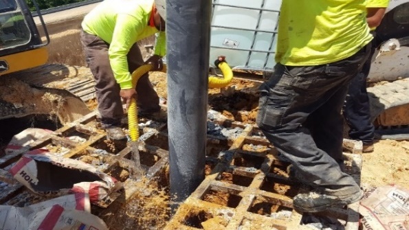
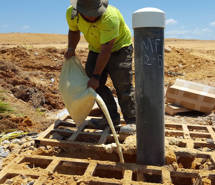
LFG Energy Project Development Handbook
Best Practices for Landfill Gas Collection System Design and Installation
7-9
Figure 7-1. Bentonite and Foam Methods for Sealing a Well
Hydrating bentonite to seal a well
Pouring foam around a well casing
Photos courtesy of Advance One Development, Inc.
Well Spacing.
Well spacing is the distance from one well to an adjacent well and typically varies from
150 to 300 feet. Well spacing is a function of the effective radius (or zone) of influence that each well can
achieve. Zones of influence typically overlap with adjacent wells to assure coverage of the landfill and
collection of LFG. Factors that affect the influence of an LFG well also affect LFG well spacing. These
factors include but are not limited to:
•
GCS design vacuum for each well
•
Waste density
•
Liquids within the waste
•
Depth of waste
•
Proximity to landfill edges
•
Cover properties
•
Goal of the GCS, e.g., compliance, electricity generation, or RNG facility.
Well spacing at a landfill does not need to be uniform. Variable well spacing takes into consideration the
differences between wells within a given landfill. For example, wells closer to the perimeter of the landfill
may be more prone to over pull, and thus require a slightly closer well spacing to allow them to achieve
coverage while operating under a slightly lower vacuum. Wells within the interior of the landfill, which
are less susceptible to air intrusion, may be spaced at a lesser density and operated at a higher rate of
vacuum.
Sites that are developing LFG energy projects, specifically RNG projects or others requiring a low degree
of balance gas or inert gas (i.e., nitrogen and oxygen), may encounter the operational issue of trying to
draw high quality fuel for the end-use project while also maintaining regulatory compliance with surface
emission standards. One solution is to decrease the overall well spacing. By locating the wells closer
together (typically less than 200 feet apart), the system can be operated efficiently with minimal potential
for ambient air intrusion due to over pull of the wells.
Another approach to producing high quality LFG is to establish “production” wells versus “control”
wells. Production wells would be developed specifically for producing higher quality fuel. These wells
are typically installed in the thicker areas of the waste mass, with a greater length of solid casing (perhaps
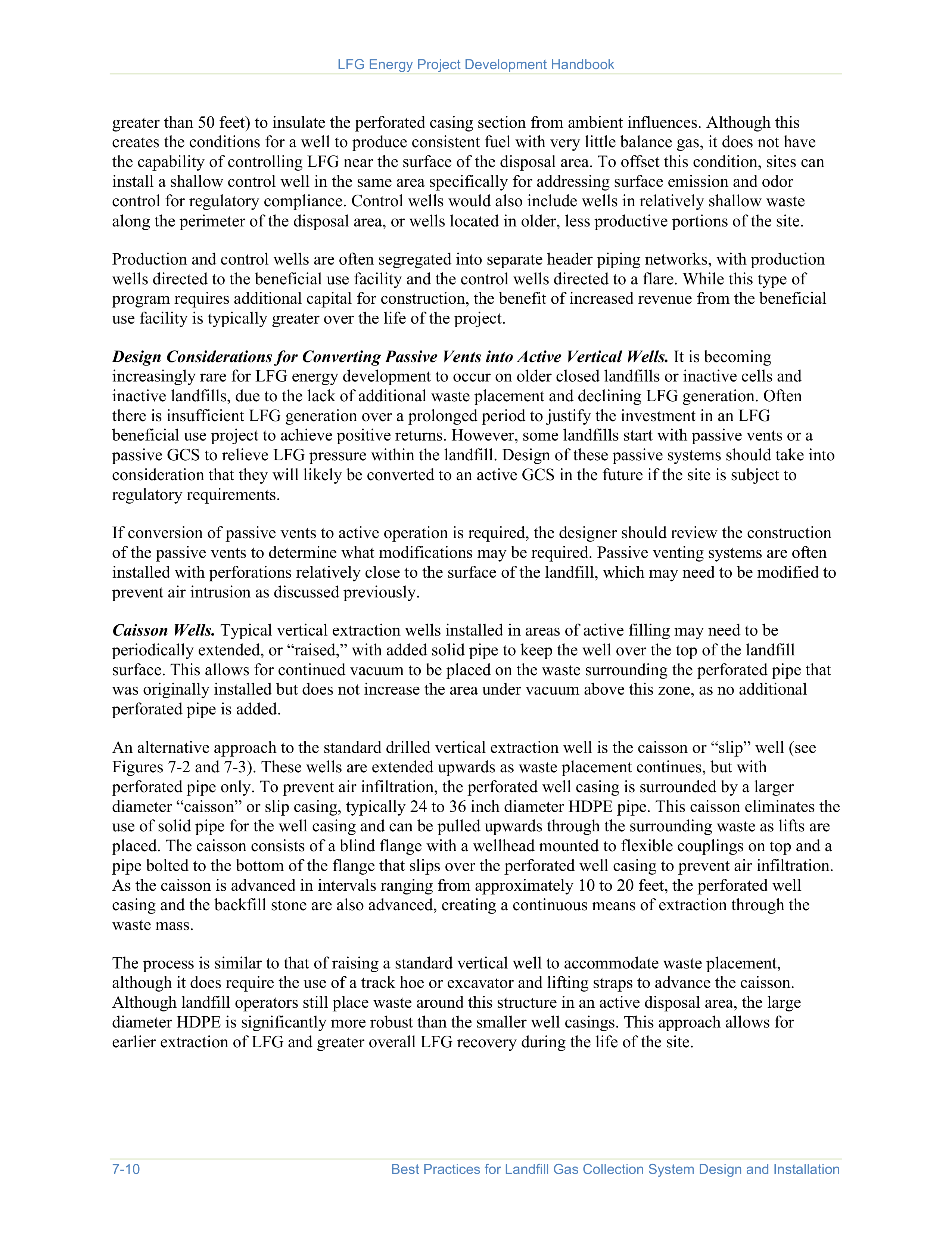
LFG Energy Project Development Handbook
7-10
Best Practices for Landfill Gas Collection System Design and Installation
greater than 50 feet) to insulate the perforated casing section from ambient influences. Although this
creates the conditions for a well to produce consistent fuel with very little balance gas, it does not have
the capability of controlling LFG near the surface of the disposal area. To offset this condition, sites can
install a shallow control well in the same area specifically for addressing surface emission and odor
control for regulatory compliance. Control wells would also include wells in relatively shallow waste
along the perimeter of the disposal area, or wells located in older, less productive portions of the site.
Production and control wells are often segregated into separate header piping networks, with production
wells directed to the beneficial use facility and the control wells directed to a flare. While this type of
program requires additional capital for construction, the benefit of increased revenue from the beneficial
use facility is typically greater over the life of the project.
Design Considerations for Converting Passive Vents into Active Vertical Wells.
It is becoming
increasingly rare for LFG energy development to occur on older closed landfills or inactive cells and
inactive landfills, due to the lack of additional waste placement and declining LFG generation. Often
there is insufficient LFG generation over a prolonged period to justify the investment in an LFG
beneficial use project to achieve positive returns. However, some landfills start with passive vents or a
passive GCS to relieve LFG pressure within the landfill. Design of these passive systems should take into
consideration that they will likely be converted to an active GCS in the future if the site is subject to
regulatory requirements.
If conversion of passive vents to active operation is required, the designer should review the construction
of the passive vents to determine what modifications may be required. Passive venting systems are often
installed with perforations relatively close to the surface of the landfill, which may need to be modified to
prevent air intrusion as discussed previously.
Caisson Wells.
Typical vertical extraction wells installed in areas of active filling may need to be
periodically extended, or “raised,” with added solid pipe to keep the well over the top of the landfill
surface. This allows for continued vacuum to be placed on the waste surrounding the perforated pipe that
was originally installed but does not increase the area under vacuum above this zone, as no additional
perforated pipe is added.
An alternative approach to the standard drilled vertical extraction well is the caisson or “slip” well (see
Figures 7-2 and 7-3). These wells are extended upwards as waste placement continues, but with
perforated pipe only. To prevent air infiltration, the perforated well casing is surrounded by a larger
diameter “caisson” or slip casing, typically 24 to 36 inch diameter HDPE pipe. This caisson eliminates the
use of solid pipe for the well casing and can be pulled upwards through the surrounding waste as lifts are
placed. The caisson consists of a blind flange with a wellhead mounted to flexible couplings on top and a
pipe bolted to the bottom of the flange that slips over the perforated well casing to prevent air infiltration.
As the caisson is advanced in intervals ranging from approximately 10 to 20 feet, the perforated well
casing and the backfill stone are also advanced, creating a continuous means of extraction through the
waste mass.
The process is similar to that of raising a standard vertical well to accommodate waste placement,
although it does require the use of a track hoe or excavator and lifting straps to advance the caisson.
Although landfill operators still place waste around this structure in an active disposal area, the large
diameter HDPE is significantly more robust than the smaller well casings. This approach allows for
earlier extraction of LFG and greater overall LFG recovery during the life of the site.
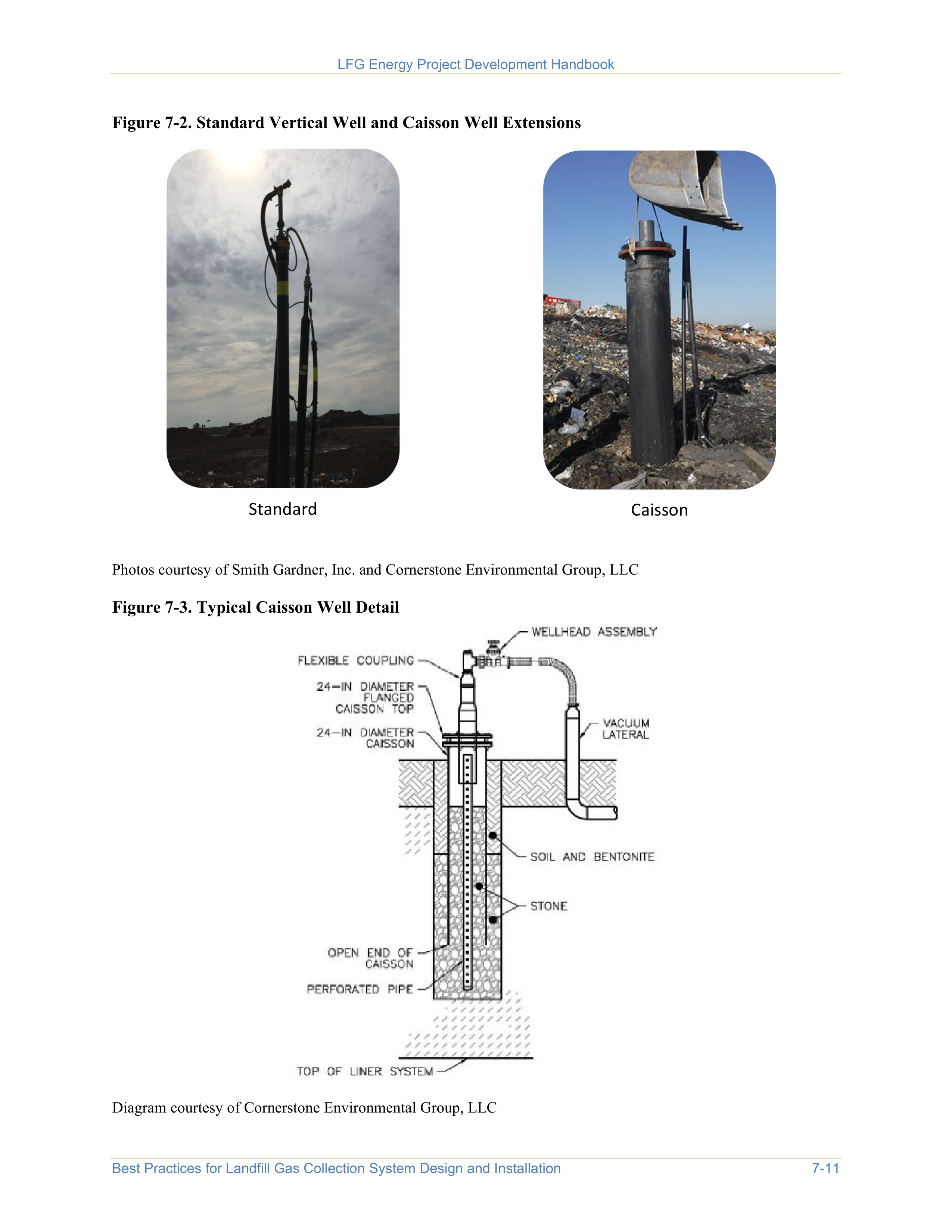
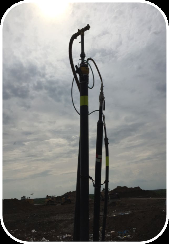
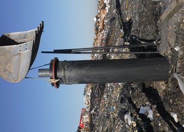
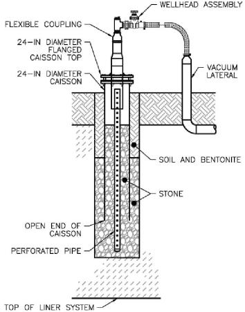
LFG Energy Project Development Handbook
Best Practices for Landfill Gas Collection System Design and Installation
7-11
Figure 7-2. Standard Vertical Well and Caisson Well Extensions
Standard
Caisson
Photos courtesy of Smith Gardner, Inc. and Cornerstone Environmental Group, LLC
Figure 7-3. Typical Caisson Well Detail
Diagram courtesy of Cornerstone Environmental Group, LLC
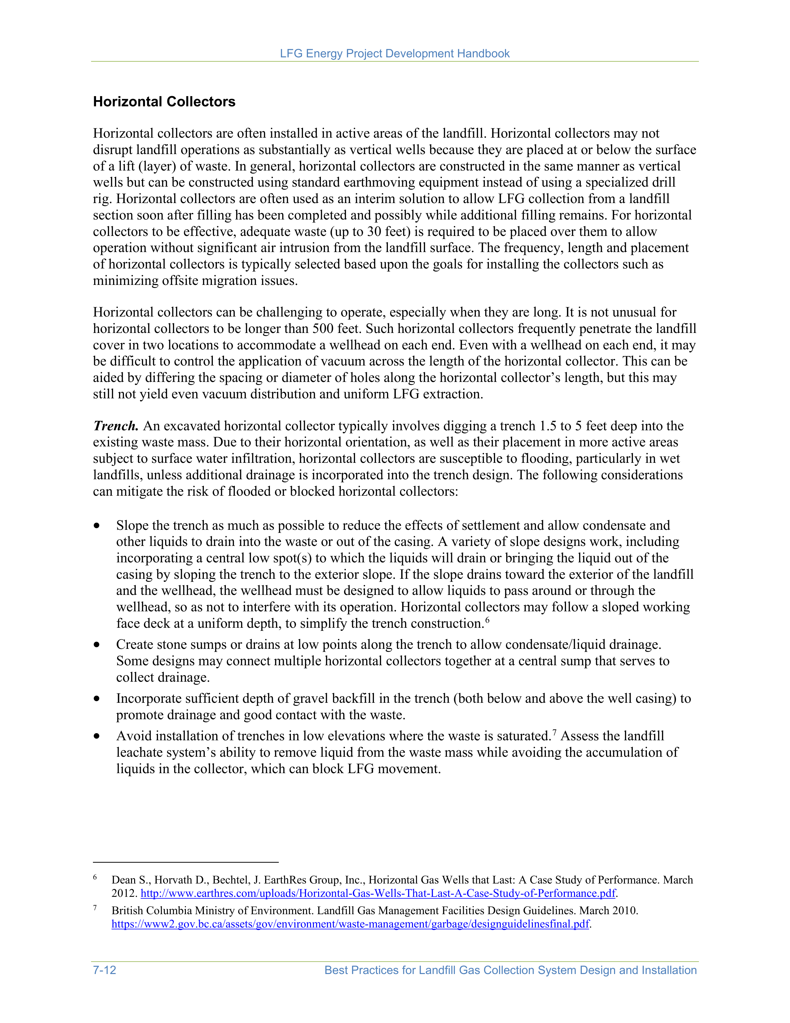
LFG Energy Project Development Handbook
7-12
Best Practices for Landfill Gas Collection System Design and Installation
Horizontal Collectors
Horizontal collectors are often installed in active areas of the landfill. Horizontal collectors may not
disrupt landfill operations as substantially as vertical wells because they are placed at or below the surface
of a lift (layer) of waste. In general, horizontal collectors are constructed in the same manner as vertical
wells but can be constructed using standard earthmoving equipment instead of using a specialized drill
rig. Horizontal collectors are often used as an interim solution to allow LFG collection from a landfill
section soon after filling has been completed and possibly while additional filling remains. For horizontal
collectors to be effective, adequate waste (up to 30 feet) is required to be placed over them to allow
operation without significant air intrusion from the landfill surface. The frequency, length and placement
of horizontal collectors is typically selected based upon the goals for installing the collectors such as
minimizing offsite migration issues.
Horizontal collectors can be challenging to operate, especially when they are long. It is not unusual for
horizontal collectors to be longer than 500 feet. Such horizontal collectors frequently penetrate the landfill
cover in two locations to accommodate a wellhead on each end. Even with a wellhead on each end, it may
be difficult to control the application of vacuum across the length of the horizontal collector. This can be
aided by differing the spacing or diameter of holes along the horizontal collector’s length, but this may
still not yield even vacuum distribution and uniform LFG extraction.
Trench.
An excavated horizontal collector typically involves digging a trench 1.5 to 5 feet deep into the
existing waste mass. Due to their horizontal orientation, as well as their placement in more active areas
subject to surface water infiltration, horizontal collectors are susceptible to flooding, particularly in wet
landfills, unless additional drainage is incorporated into the trench design. The following considerations
can mitigate the risk of flooded or blocked horizontal collectors:
•
Slope the trench as much as possible to reduce the effects of settlement and allow condensate and
other liquids to drain into the waste or out of the casing. A variety of slope designs work, including
incorporating a central low spot(s) to which the liquids will drain or bringing the liquid out of the
casing by sloping the trench to the exterior slope. If the slope drains toward the exterior of the landfill
and the wellhead, the wellhead must be designed to allow liquids to pass around or through the
wellhead, so as not to interfere with its operation. Horizontal collectors may follow a sloped working
face deck at a uniform depth, to simplify the trench construction.
6
•
Create stone sumps or drains at low points along the trench to allow condensate/liquid drainage.
Some designs may connect multiple horizontal collectors together at a central sump that serves to
collect drainage.
•
Incorporate sufficient depth of gravel backfill in the trench (both below and above the well casing) to
promote drainage and good contact with the waste.
•
Avoid installation of trenches in low elevations where the waste is saturated.
7
Assess the landfill
leachate system’s ability to remove liquid from the waste mass while avoiding the accumulation of
liquids in the collector, which can block LFG movement.
6
Dean S., Horvath D., Bechtel, J. EarthRes Group, Inc., Horizontal Gas Wells that Last: A Case Study of Performance. March
2012.
http://www.earthres.com/uploads/Horizontal-Gas-Wells-That-Last-A-Case-Study-of-Performance.pdf
.
7
British Columbia Ministry of Environment. Landfill Gas Management Facilities Design Guidelines. March 2010.
https://www2.gov.bc.ca/assets/gov/environment/waste-management/garbage/designguidelinesfinal.pdf
.
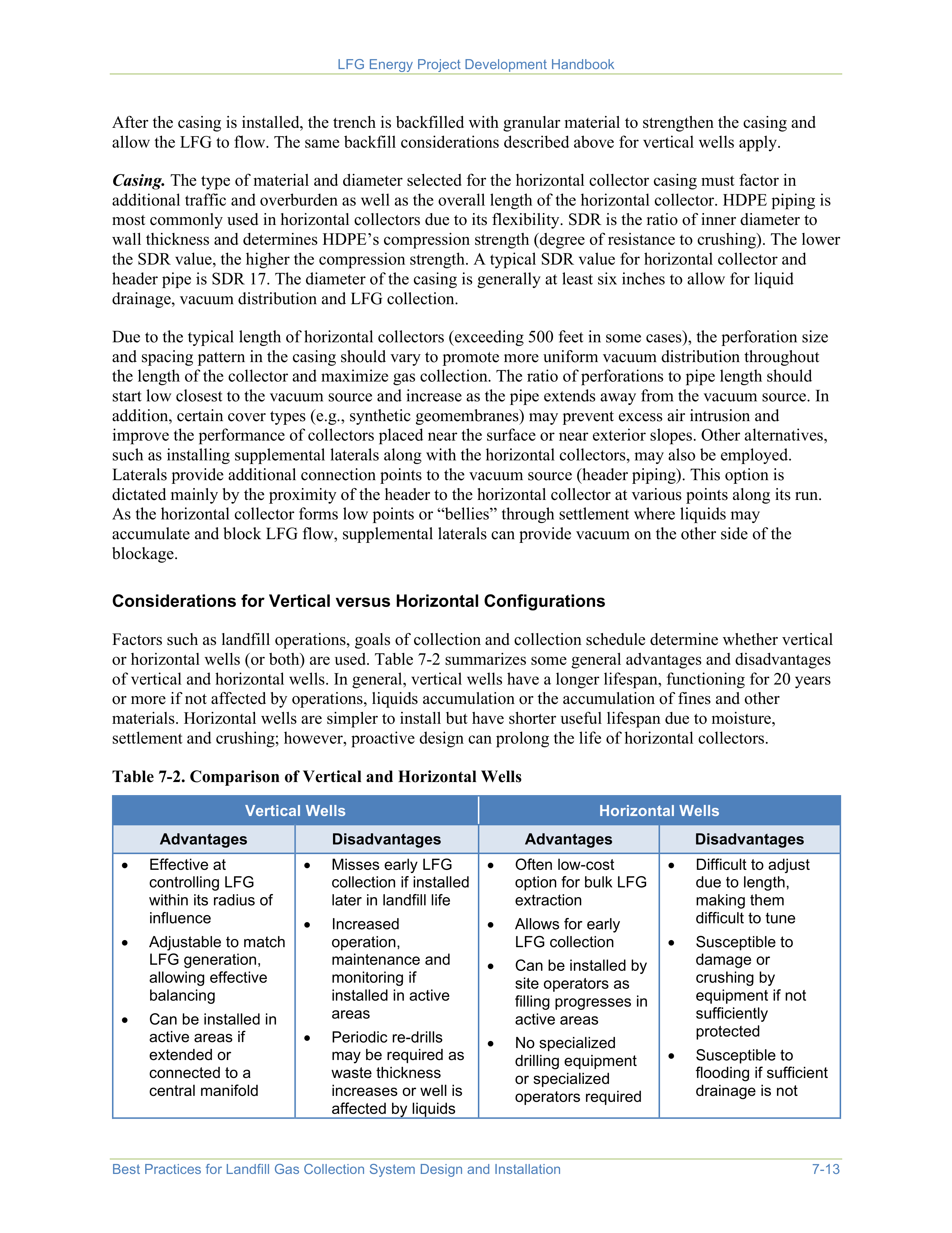
LFG Energy Project Development Handbook
Best Practices for Landfill Gas Collection System Design and Installation
7-13
After the casing is installed, the trench is backfilled with granular material to strengthen the casing and
allow the LFG to flow. The same backfill considerations described above for vertical wells apply.
Casing.
The type of material and diameter selected for the horizontal collector casing must factor in
additional traffic and overburden as well as the overall length of the horizontal collector. HDPE piping is
most commonly used in horizontal collectors due to its flexibility. SDR is the ratio of inner diameter to
wall thickness and determines HDPE’s compression strength (degree of resistance to crushing). The lower
the SDR value, the higher the compression strength. A typical SDR value for horizontal collector and
header pipe is SDR 17. The diameter of the casing is generally at least six inches to allow for liquid
drainage, vacuum distribution and LFG collection.
Due to the typical length of horizontal collectors (exceeding 500 feet in some cases), the perforation size
and spacing pattern in the casing should vary to promote more uniform vacuum distribution throughout
the length of the collector and maximize gas collection. The ratio of perforations to pipe length should
start low closest to the vacuum source and increase as the pipe extends away from the vacuum source. In
addition, certain cover types (e.g., synthetic geomembranes) may prevent excess air intrusion and
improve the performance of collectors placed near the surface or near exterior slopes. Other alternatives,
such as installing supplemental laterals along with the horizontal collectors, may also be employed.
Laterals provide additional connection points to the vacuum source (header piping). This option is
dictated mainly by the proximity of the header to the horizontal collector at various points along its run.
As the horizontal collector forms low points or “bellies” through settlement where liquids may
accumulate and block LFG flow, supplemental laterals can provide vacuum on the other side of the
blockage.
Considerations for Vertical versus Horizontal Configurations
Factors such as landfill operations, goals of collection and collection schedule determine whether vertical
or horizontal wells (or both) are used. Table 7-2 summarizes some general advantages and disadvantages
of vertical and horizontal wells. In general, vertical wells have a longer lifespan, functioning for 20 years
or more if not affected by operations, liquids accumulation or the accumulation of fines and other
materials. Horizontal wells are simpler to install but have shorter useful lifespan due to moisture,
settlement and crushing; however, proactive design can prolong the life of horizontal collectors.
Table 7-2. Comparison of Vertical and Horizontal Wells
Vertical Wells
Horizontal Wells
Advantages
Disadvantages
Advantages
Disadvantages
•
Effective at
controlling LFG
within its radius of
influence
•
Adjustable to match
LFG generation,
allowing effective
balancing
•
Can be installed in
active areas if
extended or
connected to a
central manifold
•
Misses early LFG
collection if installed
later in landfill life
•
Increased
operation,
maintenance and
monitoring if
installed in active
areas
•
Periodic re-drills
may be required as
waste thickness
increases or well is
affected by liquids
•
Often low-cost
option for bulk LFG
extraction
•
Allows for early
LFG collection
•
Can be installed by
site operators as
filling progresses in
active areas
•
No specialized
drilling equipment
or specialized
operators required
•
Difficult to adjust
due to length,
making them
difficult to tune
•
Susceptible to
damage or
crushing by
equipment if not
sufficiently
protected
•
Susceptible to
flooding if sufficient
drainage is not
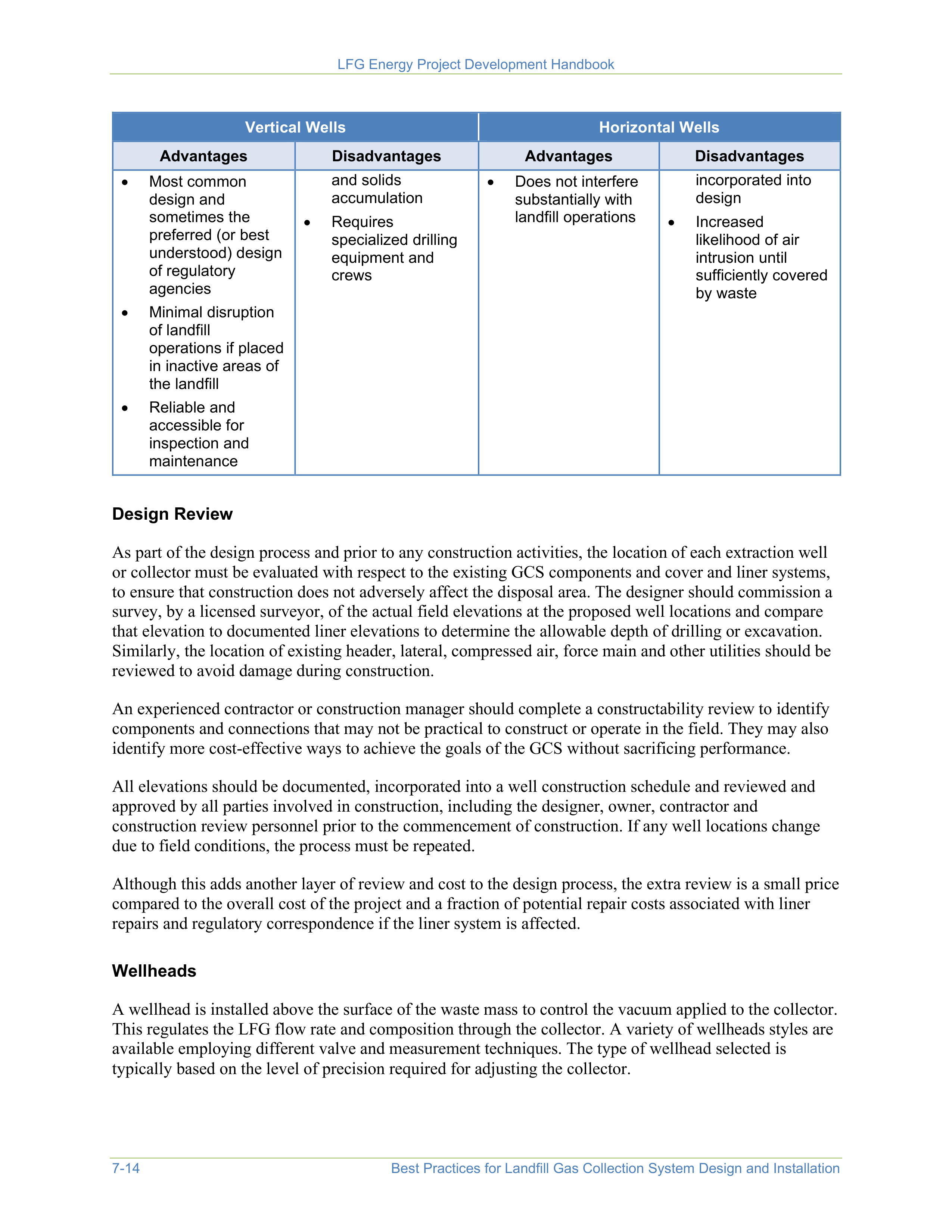
LFG Energy Project Development Handbook
7-14
Best Practices for Landfill Gas Collection System Design and Installation
Vertical Wells
Horizontal Wells
Advantages
Disadvantages
Advantages
Disadvantages
•
Most common
design and
sometimes the
preferred (or best
understood) design
of regulatory
agencies
•
Minimal disruption
of landfill
operations if placed
in inactive areas of
the landfill
•
Reliable and
accessible for
inspection and
maintenance
and solids
accumulation
•
Requires
specialized drilling
equipment and
crews
•
Does not interfere
substantially with
landfill operations
incorporated into
design
•
Increased
likelihood of air
intrusion until
sufficiently covered
by waste
Design Review
As part of the design process and prior to any construction activities, the location of each extraction well
or collector must be evaluated with respect to the existing GCS components and cover and liner systems,
to ensure that construction does not adversely affect the disposal area. The designer should commission a
survey, by a licensed surveyor, of the actual field elevations at the proposed well locations and compare
that elevation to documented liner elevations to determine the allowable depth of drilling or excavation.
Similarly, the location of existing header, lateral, compressed air, force main and other utilities should be
reviewed to avoid damage during construction.
An experienced contractor or construction manager should complete a constructability review to identify
components and connections that may not be practical to construct or operate in the field. They may also
identify more cost-effective ways to achieve the goals of the GCS without sacrificing performance.
All elevations should be documented, incorporated into a well construction schedule and reviewed and
approved by all parties involved in construction, including the designer, owner, contractor and
construction review personnel prior to the commencement of construction. If any well locations change
due to field conditions, the process must be repeated.
Although this adds another layer of review and cost to the design process, the extra review is a small price
compared to the overall cost of the project and a fraction of potential repair costs associated with liner
repairs and regulatory correspondence if the liner system is affected.
Wellheads
A wellhead is installed above the surface of the waste mass to control the vacuum applied to the collector.
This regulates the LFG flow rate and composition through the collector. A variety of wellheads styles are
available employing different valve and measurement techniques. The type of wellhead selected is
typically based on the level of precision required for adjusting the collector.
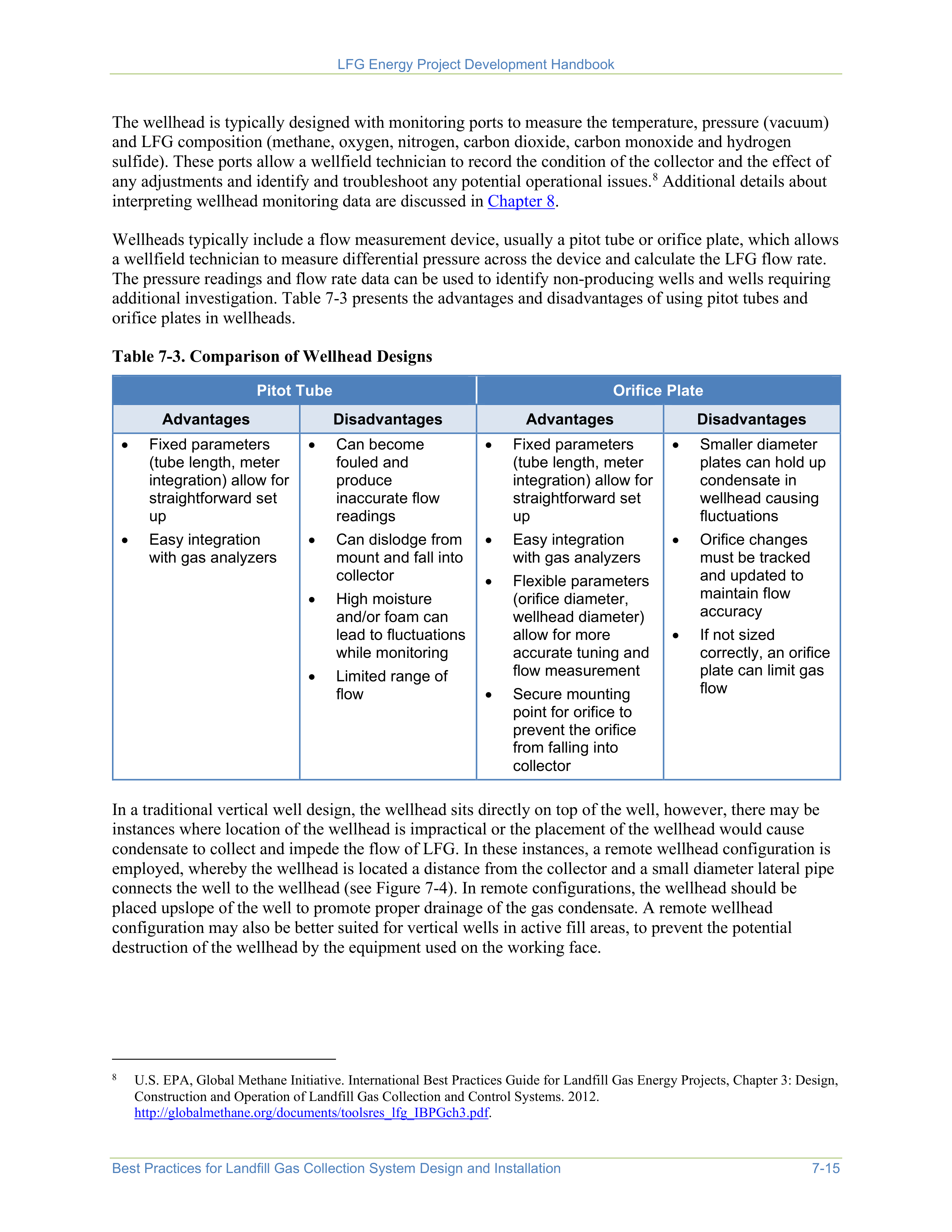
LFG Energy Project Development Handbook
Best Practices for Landfill Gas Collection System Design and Installation
7-15
The wellhead is typically designed with monitoring ports to measure the temperature, pressure (vacuum)
and LFG composition (methane, oxygen, nitrogen, carbon dioxide, carbon monoxide and hydrogen
sulfide). These ports allow a wellfield technician to record the condition of the collector and the effect of
any adjustments and identify and troubleshoot any potential operational issues.
8
Additional details about
interpreting wellhead monitoring data are discussed in
Chapter 8
.
8
U.S. EPA, Global Methane Initiative. International Best Practices Guide for Landfill Gas Energy Projects, Chapter 3: Design,
Construction and Operation of Landfill Gas Collection and Control Systems. 2012.
http://globalmethane.org/documents/toolsres_lfg_IBPGch3.pdf
.
Wellheads typically include a flow measurement device, usually a pitot tube or orifice plate, which allows
a wellfield technician to measure differential pressure across the device and calculate the LFG flow rate.
The pressure readings and flow rate data can be used to identify non-producing wells and wells requiring
additional investigation. Table 7-3 presents the advantages and disadvantages of using pitot tubes and
orifice plates in wellheads.
Table 7-3. Comparison of Wellhead Designs
Pitot Tube
Orifice Plate
Advantages
Disadvantages
Advantages
Disadvantages
•
Fixed parameters
(tube length, meter
integration) allow for
straightforward set
up
•
Easy integration
with gas analyzers
•
Can become
fouled and
produce
inaccurate flow
readings
•
Can dislodge from
mount and fall into
collector
•
High moisture
and/or foam can
lead to fluctuations
while monitoring
•
Limited range of
flow
•
Fixed parameters
(tube length, meter
integration) allow for
straightforward set
up
•
Easy integration
with gas analyzers
•
Flexible parameters
(orifice diameter,
wellhead diameter)
allow for more
accurate tuning and
flow measurement
•
Secure mounting
point for orifice to
prevent the orifice
from falling into
collector
•
Smaller diameter
plates can hold up
condensate in
wellhead causing
fluctuations
•
Orifice changes
must be tracked
and updated to
maintain flow
accuracy
•
If not sized
correctly, an orifice
plate can limit gas
flow
In a traditional vertical well design, the wellhead sits directly on top of the well, however, there may be
instances where location of the wellhead is impractical or the placement of the wellhead would cause
condensate to collect and impede the flow of LFG. In these instances, a remote wellhead configuration is
employed, whereby the wellhead is located a distance from the collector and a small diameter lateral pipe
connects the well to the wellhead (see Figure 7-4). In remote configurations, the wellhead should be
placed upslope of the well to promote proper drainage of the gas condensate. A remote wellhead
configuration may also be better suited for vertical wells in active fill areas, to prevent the potential
destruction of the wellhead by the equipment used on the working face.
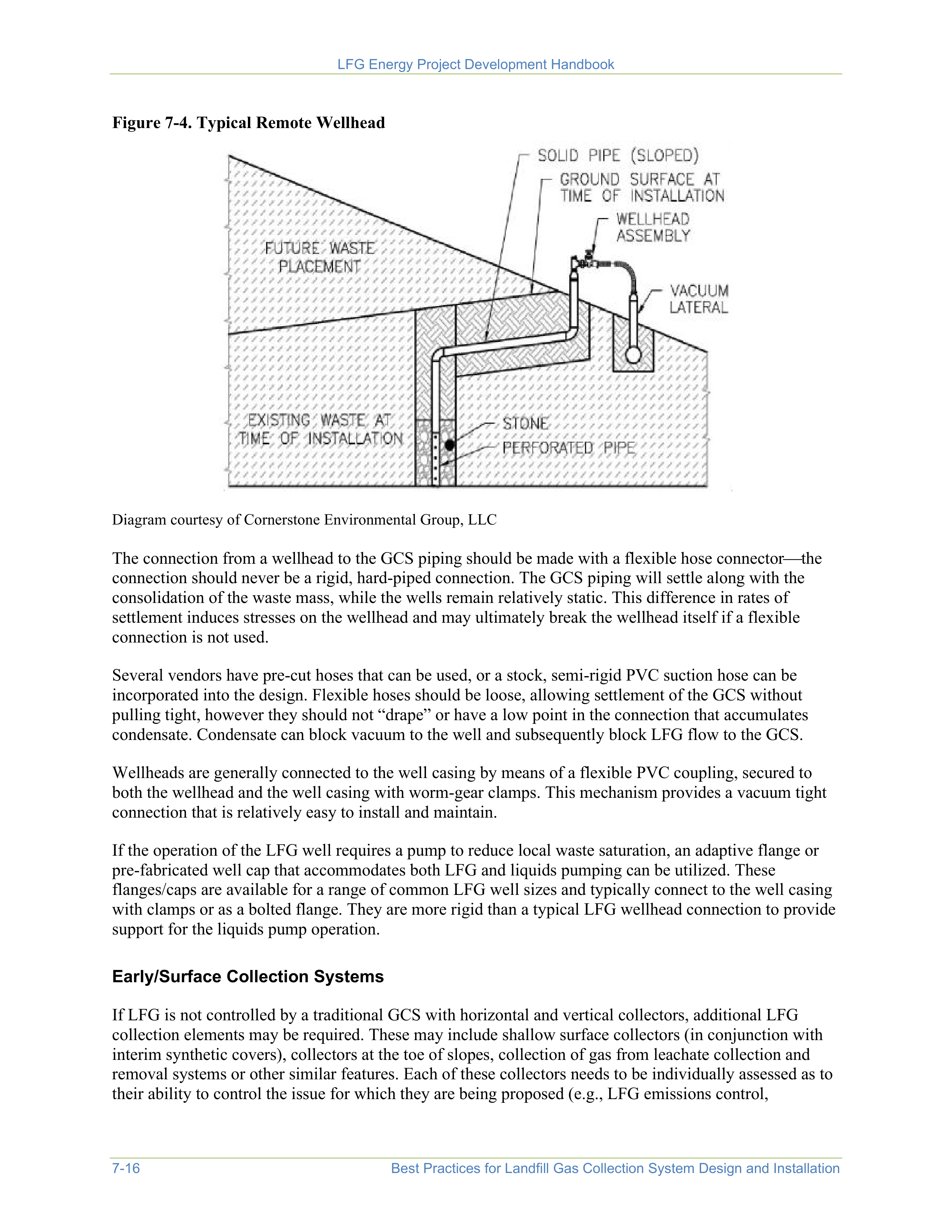
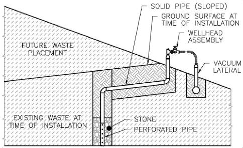
LFG Energy Project Development Handbook
7-16
Best Practices for Landfill Gas Collection System Design and Installation
Figure 7-4. Typical Remote Wellhead
Diagram courtesy of Cornerstone Environmental Group, LLC
The connection from a wellhead to the GCS piping should be made with a flexible hose connector
the
connection should never be a rigid, hard-piped connection. The GCS piping will settle along with the
consolidation of the waste mass, while the wells remain relatively static. This difference in rates of
settlement induces stresses on the wellhead and may ultimately break the wellhead itself if a flexible
connection is not used.
Several vendors have pre-cut hoses that can be used, or a stock, semi-rigid PVC suction hose can be
incorporated into the design. Flexible hoses should be loose, allowing settlement of the GCS without
pulling tight, however they should not “drape” or have a low point in the connection that accumulates
condensate. Condensate can block vacuum to the well and subsequently block LFG flow to the GCS.
Wellheads are generally connected to the well casing by means of a flexible PVC coupling, secured to
both the wellhead and the well casing with worm-gear clamps. This mechanism provides a vacuum tight
connection that is relatively easy to install and maintain.
If the operation of the LFG well requires a pump to reduce local waste saturation, an adaptive flange or
pre-fabricated well cap that accommodates both LFG and liquids pumping can be utilized. These
flanges/caps are available for a range of common LFG well sizes and typically connect to the well casing
with clamps or as a bolted flange. They are more rigid than a typical LFG wellhead connection to provide
support for the liquids pump operation.
Early/Surface Collection Systems
If LFG is not controlled by a traditional GCS with horizontal and vertical collectors, additional LFG
collection elements may be required. These may include shallow surface collectors (in conjunction with
interim synthetic covers), collectors at the toe of slopes, collection of gas from leachate collection and
removal systems or other similar features. Each of these collectors needs to be individually assessed as to
their ability to control the issue for which they are being proposed (e.g., LFG emissions control,
LFG Energy Project Development Handbook
Best Practices for Landfill Gas Collection System Design and Installation
7-17
preventing pressure beneath a liner) and their ability to service as a suitable collector for a potential LFG
energy project.
The performance of these alternate collectors depends on site-specific factors. Air infiltration is always a
concern and may be minimized through cover placement and/or the use of a synthetic cover. Vacuum
control is also critical; wellheads with collection valves capable of fine tuning should be used.
7.3
Lateral and Header Piping
To get LFG from the individual collectors to the central processing point, a series of lateral and header
pipes is installed around the perimeter and into the interior of the landfill. Typically, the laterals and
headers are installed in a phased manner that follows the progression of the development of the landfill
with provisions for isolating portions of the system, minimizing head loss and draining condensate.
Lateral and header piping should be designed based on site-specific conditions such as expected LFG
generation rates, landfill progression plans, obstructions in the landfill, existing systems and other field
conditions. Site development and fill progression plans should be assessed to integrate pipe sizes and
alignment along with phasing of the installation.
Placement
Landfill geometry, fill progression, development plans, end use plans, collector placement and spacing,
waste types, location of landfill feature, settlement rates and provisions for condensate collection are
among the factors that should be considered when laying out the system. The GCS layout should use the
site topography where possible to achieve the desired slopes. Industry practice is to design the system
with multiple pathways for gas flow (i.e., “loops”) in the header piping, providing redundancy for
extraction during periods of site development and periodic maintenance or repairs to the header system
and to compartmentalize the operations of different sections of the wellfield based upon relative
performance of the extraction wells. The header system generally consists of a full loop around the
perimeter of the disposal area, with “crossover” headers running between opposing side slopes.
This practice generally allows the use of smaller headers because the flow is distributed between more
piping sections and more uniform distribution of vacuum to the extraction points. It also aids in the
management of LFG condensate as the flows are more discrete from each section and can be managed
more proactively than in a single header.
The layout should have sufficient pipe slope to prevent condensate blockage and ensure drainage to
condensate disposal locations. Typical industry practice is to design header piping at a minimum of
4 percent slope in counter-current conditions and 2 percent in concurrent conditions. Headers placed
outside the limits of waste may be designed at a lesser slope, depending upon the site conditions.
Regardless of the location, the header piping should be designed to utilize the maximum grade practical to
reduce the potential impact of future differential settlement.
One major consideration when developing the layout for a GCS is ensuring that excessive waste
settlement does not result in low points in the piping network that trap condensate and block the header
lines. If feasible, the header piping should follow landfill features such as surface water management
berms, roadways and natural topography. This facilitates installation and maintenance of the header
lines.
9
9
U.S. Army Corps of Engineers. Landfill Gas Collection and Treatment Systems Engineer Manual. April 2013.
http://www.publications.usace.army.mil/Portals/76/Publications/EngineerManuals/EM_200-1-22.pdf?ver=2013-09-05-
152155-217
.
However, allowing interim low points, without the ability to actively drain condensate, is not an
LFG Energy Project Development Handbook
7-18
Best Practices for Landfill Gas Collection System Design and Installation
acceptable design practice. This condition may occur when running header lines over surface water
drainage features such as berms and channels or when sudden changes in grade are not considered.
Materials
The GCS piping materials should be selected by considering the field conditions and environmental
exposure. As described in Table 7-1, HDPE pipe is generally preferred for laterals and headers because
the pipe is flexible over uneven terrain and long distances and can handle differential movement of the
waste reasonably well. HDPE also has good resistance to sunlight and the constituents within LFG,
allowing its utilization across the landfill surface and in harsh environments. PVC pipe can become brittle
in sunlight even within a short period of time and is not preferred for above ground pipe installations. The
rigidity of PVC pipe does not allow it to accommodate the differential movement within landfills as well
as HDPE, so PVC is not commonly used for header or lateral piping.
HDPE piping has a relatively high modular elasticity related to temperature changes (i.e., the pipe will
expand when warmed and shrink when cooled). To prevent degradation of HDPE pipe from sunlight,
carbon black is usually mixed with the HDPE resin during manufacture of the pipe, which turns the pipe
black, enabling it to absorb more sunlight than a lighter colored pipe. However, this absorption of sunlight
results in additional thermal changes in the pipe. Thus, header and lateral piping is often placed in shallow
trenches within the landfill to minimize the exposure to sunlight and to restrain the pipe from movement.
When installed above ground, HDPE piping should be anchored with pipe guides or soil mounds to direct
the piping movement and maintain its alignment, slope and grade.
Size
Piping size should be designed to accommodate the maximum expected LFG flow rates. Isothermal gas
flow modeling software can be used to help determine the appropriate pipe size and determine the
distribution of vacuum throughout the wellfield. Calculations utilized to model LFG piping systems
include, but are not limited to, Darcy-Weisbach, Spitzglass and Mueller. According to the U.S. Army
Corps of Engineers,
10
pipes should generally be sized for approximately 1 inch of water column (in. WC)
pressure drop per 100 feet of pipe.
10
U.S. Army Corps of Engineers. Landfill Gas Collection and Treatment Systems Engineer Manual. April 2013.
http://www.publications.usace.army.mil/Portals/76/Publications/EngineerManuals/EM_200-1-22.pdf?ver=2013-09-05-
152155-217
.
Condensate accumulation and removal is another consideration when sizing LFG piping. LFG is usually
considered to be saturated with water vapor that condenses inside GCS piping. The condensate generally
flows via gravity within the headers and lateral piping to an engineered low point for removal via a pump
station or drain. Condensate can accumulate in headers and laterals if there is insufficient slope on the
pipe or if settling of the waste results in an unintended low point in the pipe that cannot be drained.
Velocities of LFG in the header piping are typically limited to allow the condensate to flow freely. If the
LFG velocity within a pipe becomes too great, it will generate a hydraulic lift of the condensate within the
header, forming a temporary obstruction within the pipe. These obstructions can cause the LFG flow to
suddenly decrease then increase, creating “surges” in vacuum distribution. If left unchecked these surges
result in condensate build-up that prevents the flow of LFG.
Vacuum surges can hamper system performance and may damage mechanical equipment such as the
blowers and compressors. Typical industry practice is to limit LFG velocity to no more than 20 feet per
second when the LFG flow is counter-current to the condensate flow (LFG is flowing uphill and
LFG Energy Project Development Handbook
Best Practices for Landfill Gas Collection System Design and Installation
7-19
condensate is flowing downhill) and the LFG velocity is limited to no more than 40 feet per second when
the LFG flow is concurrent to the condensate flow (LFG and condensate are both flowing downhill).
Other considerations may need to be given for long runs of pipe without condensate removal devices or
sections of pipes anticipated to have abnormally high levels of condensate.
Note that these limitations are guidance only and not regulatorily defined. An assessment of each landfill,
including the relative moisture of the LFG and projected rates of differential settlement within the waste
mass, should be evaluated as part of the system design process.
7.4
Condensate Management
LFG is usually considered to be saturated with water vapor, and in the process of removing LFG from the
collectors, the water vapor condenses out of the gas and forms condensate inside GCS components. The
GCS should be designed so this condensate drains to an engineered low point(s) in the header system for
removal via a pump station or drain.
A pump station is essentially a sealed wet-well constructed either in-line with the header piping or offset
from the header as a separate structure. Condensate drains into the pump station and is periodically
pumped, using either electrical or pneumatic pumping components, to a centralized treatment or storage
facility. The designer should ensure that an adequate supply of either compressed air (conditioned for the
application) or electrical service of the correct voltage and amperage is available for the pump station.
Electric and pneumatic pumping systems are both widely used in condensate management applications.
A drain, also known as a trap or drip leg, allows condensate to drain from an evacuated system to an
ambient storage vessel such as a tank or lift station, without allowing ambient air intrusion into the GCS.
It is very similar to a P-trap used in the drain for a standard sink.
In some instances, condensate is drained back into the waste mass through traps and drainage into rock-
filled dissipation features. However, these condensate disposal features can become clogged over time
and inhibit condensate drainage into the waste. Traps that drain into the waste often need to be replaced
with more permanent condensate removal systems.
Automated or gravity condensate systems that can continuously drain condensate to collection points and
convey the condensate to a centralized treatment or disposal point without operator interaction are
preferred. These automated systems frequently include electric or pneumatic pumps although other
innovative techniques like windmills can be used in limited situations.
11
11
California Integrated Solid Waste Management Board. Technologies and Management Options for Reducing Greenhouse
Gas Emissions from Landfills. April 2008.
https://www2.calrecycle.ca.gov/Publications/Details/1268
.
Regardless of the type of condensate management system used, it must be designed for the full range of
vacuum application intended for the GCS, possess sufficient throughput volume for the design condensate
flow and be capable of maintaining a seal between ambient conditions and the applied GCS vacuum. The
designer should estimate the expected condensate generation rate under the typical system vacuum
operational range using both mathematical calculations as well as experience with similar systems to
ensure sufficient condensate management capacity. Designers typically use natural gas saturation tables
or Antoine’s Equation to estimate the volume of condensate to be generated within a GCS. The GCS
LFG Energy Project Development Handbook
7-20
Best Practices for Landfill Gas Collection System Design and Installation
should be designed with an adequate number, size and location of condensate collection points to remove
the anticipated condensate from the lateral and header pipes to minimize disruptions to the GCS.
12
12
California Integrated Solid Waste Management Board. Technologies and Management Options for Reducing Greenhouse
Gas Emissions from Landfills. April 2008.
https://www2.calrecycle.ca.gov/Publications/Details/1268
.
Condensate disposal options should be investigated based on specific conditions at each site, but may
include injection into the flare for incineration, disposal within a sanitary sewer or comingling with
leachate for disposal.
13
Factors such as the location of leachate disposal points (e.g., force mains and
leachate risers) and availability of compressed air and electrical service helps determine the location and
design of condensate management features.
13
U.S. Army Corps of Engineers. Landfill Gas Collection and Treatment Systems Engineer Manual, page 3-28. April 2013.
http://www.publications.usace.army.mil/Portals/76/Publications/EngineerManuals/EM_200-1-22.pdf?ver=2013-09-05-
152155-217
.
7.5
Blowers and Compressors
Blowers and compressors are critical components of an active GCS because they provide the motive force
used to collect LFG from the landfill and push it to the flare or beneficial use equipment. Both devices are
designed to apply a vacuum on the GCS. A blower typically delivers a total static pressure of less than 2
pounds-force per square inch gauge (psig) (55 in. WC) whereas, a compressor can be designed to deliver
pressures from 5 psig up to hundreds of psig. The device is usually selected based on the GCS design and
the end use of the LFG. For flare applications, blowers are typically adequate. However, LFG energy
projects like electricity generation, medium-Btu or RNG production typically require higher pressures
that could necessitate the use of a compressor.
Sizing and Type
When designing blowers and compressors and their associated piping, the designer should work with a
blower manufacturer or specialized LFG skid fabricator to develop equipment specifications based on
several considerations, including:
•
Estimated flow rates.
The LFG collection rate must fall within the equipment’s operating range. The
goal is to provide sufficient capacity and horsepower to efficiently collect the anticipated LFG flow.
•
System vacuum requirements.
Most blowers and compressors can be equipped with a variable
frequency drive (VFD), which allows for the vacuum applied to the GCS to be consistently
maintained to maximize performance.
14
Establishing a consistent level of vacuum application is
critical to achieving and maintaining effective GCS operation.
14
California Integrated Solid Waste Management Board. Technologies and Management Options for Reducing Greenhouse
Gas Emissions from Landfills, page 44. April 2008.
https://www2.calrecycle.ca.gov/Publications/Details/1268
.
•
Future development plans.
The equipment should allow for changes in LFG flow rate over time.
Often, multiple smaller blowers and compressors are installed in parallel to allow the system to be
scaled up or down as the LFG flow rates change and to provide redundancy in the system.
•
Potential end-use requirements.
Destruction or beneficial end uses such as flares, engines or RNG
projects have different discharge pressure requirements and may require staged blowers or
compressors in series to meet the pressure requirements.
•
Compatible materials.
Materials compatible with LFG and LFG condensate should be used, including
protective coatings where applicable. Aluminum components should be avoided because they
typically degrade in contact with LFG condensate.
LFG Energy Project Development Handbook
Best Practices for Landfill Gas Collection System Design and Installation
7-21
•
Power availability.
Small blowers (less than 10 horsepower) can be operated on single phase power.
Larger units require three-phase power or the use of phase converters to mimic three-phase. It may be
necessary to extend or increase the capacity of the electric service to the project area.
Correct sizing and specifications of the equipment can minimize downtimes during future operations by
avoiding flow restrictions or blower surges.
15
Pump and air compressor vendors are a great resource in
determining site-specific requirements.
15
California Integrated Solid Waste Management Board. Technologies and Management Options for Reducing Greenhouse
Gas Emissions from Landfills, page 47. April 2008.
https://www2.calrecycle.ca.gov/Publications/Details/1268
.
Condensate Management
The effective management of condensate is critical to the successful operation and maintenance of both
blowers and compressors. In addition to condensate collection and removal in the lateral and header
piping, most manufacturers require a condensate knockout or coalescing filter before the inlet to the
blowers or compressors as part of their warranty conditions. Similarly, provisions should be made to drain
any condensed liquids from the blower casing. This reduces corrosion of the impellers and internal casing
during periods of inactivity as well as potential damage due to freezing in cold climates.
Placement
The design of the equipment should address the existing power supply conditions and capabilities of the
local power provider and grid. The equipment should be centrally located relative to the GCS with
sufficient space for expansion and oriented to provide fuel to the control device or end use. The
mechanical equipment must also be placed to allow ease of access for construction and maintenance
personnel, in an area of good drainage and preferably outside the footprint of any projected expansions of
the disposal area or other landfill facilities.
7.6
Installation Best Practices
The GCS installation step is often the result of many years of planning. Landfills must obtain multiple
permits, including permits to address solid waste, air and water regulations, and prepare detailed
construction plans for the landfill and GCS as part of the process. By the time GCS installation begins,
detailed written construction plans have been prepared or reviewed by professional engineers. However,
because most landfills operate for decades, plans may evolve to meet ongoing site-specific needs.
Construction should employ proven techniques to ensure a well-built system and a construction quality
assurance (CQA) program should be implemented to make sure that the system is built following the
required design considerations (such as pipe slopes and well depths). Field engineering decisions will
need to be made to account for unforeseen conditions at the time of construction. Construction oversight
is important to identify potential changes in the system design needed to accommodate site conditions
(e.g., changes in the filling pattern, poor waste quality, impermeable areas, discovery of asbestos and
inaccessible well locations) and to document the as-built condition of the system.
16
16
U.S. EPA, Global Methane Initiative. International Best Practices Guide for Landfill Gas Energy Projects, Chapter 3: Design,
Construction and Operation of Landfill Gas Collection and Control Systems. 2012.
http://globalmethane.org/documents/toolsres_lfg_IBPGch3.pdf
.


LFG Energy Project Development Handbook
7-22
Best Practices for Landfill Gas Collection System Design and Installation
Surveying and Documentation
A qualified individual or entity should be identified or hired to provide CQA to monitor and document the
techniques used to construct the GCS. The CQA representative generally should be independent from the
entity doing the construction work to provide assurances that the work meets necessary requirements and
shortcuts are not undertaken. CQA requirements and their implementation vary by state regulatory
requirements or by internal company CQA operating procedures. In addition, many GCS engineers and
designers will require CQA for their design certification process.
A documented record or survey of as-built components of the
GCS is important to ensure landfill operators can pinpoint the
location of components in the future to address maintenance
issues or expansion of the system. Survey data should also be
provided to the design engineer for comparison to the existing
construction drawings. Revisions and updates to future
constructions may be needed to ensure the system is effective
at collecting LFG and is reliable for many years to come.
Many regulatory agencies
require CQA documentation
and survey of permanent LFG
components in the wellfield
before issuing an approval
letter to commence operation.
Following are several best practices for documenting the construction and installation of a GCS:
•
Survey LFG collector locations immediately prior to drilling or installation. A licensed third-party
surveyor should complete surveys.
•
Update the vertical well drilling schedule with the most recent surface elevation survey data and
surveyed liner elevation data from the base liner CQA report(s). The well schedule must be approved
by the LFG system design engineer, as well as the landfill’s representatives, CQA staff and drilling
personnel prior to installation.
•
Survey relocated collectors and obtain approval of the updated well schedule, prior to installation.
•
Document vertical borehole conditions during drilling, including waste type, stage of decomposition,
temperature and moisture.
•
Prior to the contractor beginning any vertical drilling or installation, the designated CQA monitor
should verify the elevation and depth of the collector based on the existing or as-built construction
drawings to avoid drilling through the landfill liner.
•
Survey as-built conditions of all new LFG system components, including collectors, laterals and
headers. Survey data should include at a minimum the horizontal and vertical location of all installed
system components every 100 feet, all directional changes, piping size transitions, valves, condensate
sumps and traps and special assemblies.
•
Document the as-built conditions in a CQA Report, including a Record Construction Drawing
defining the actual extent of construction, photographic logs of construction activities, daily CQA
reports and any testing documentation (e.g., pipe pressure testing, soils and geosynthetics testing).
Wells installed in active fill areas should be clearly marked with bright colored cones or flagging to
minimize the risk of damage by compaction equipment. In addition, effectively training and coordinating
the installation with all staff who work on the active areas will help minimize damage. Even when
incorporating operator training, given the challenges of installing and extending wells in an active filling
zone, landfill owners/operators should plan for a higher rate of repairs and/or replacement wells in active
areas.
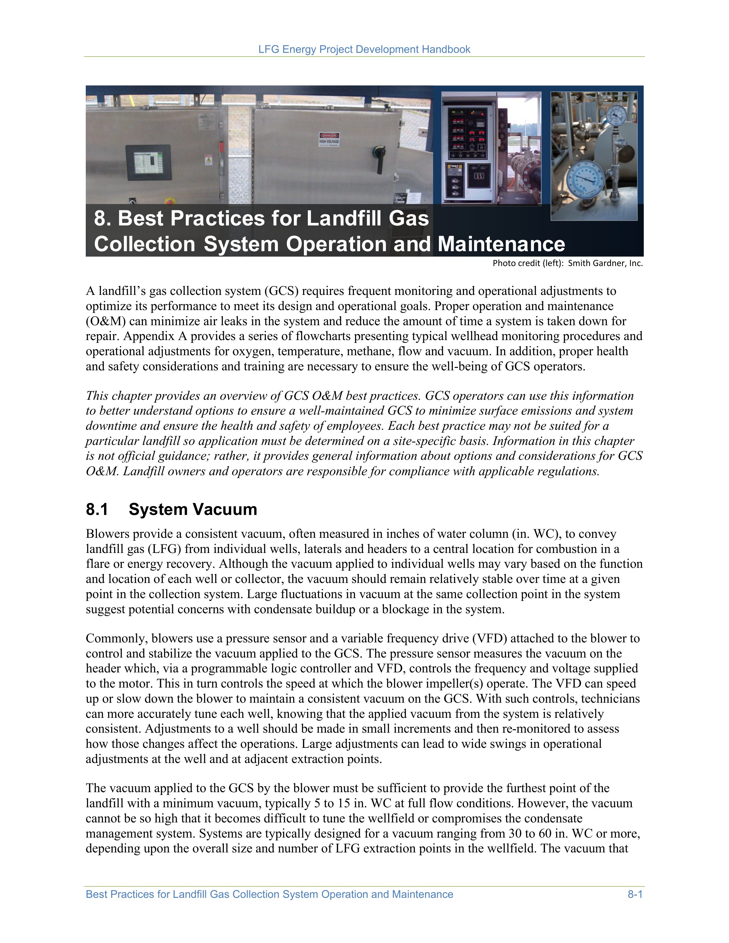
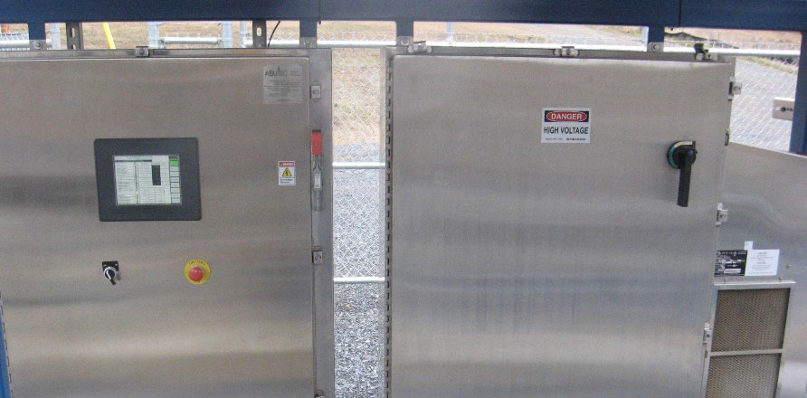
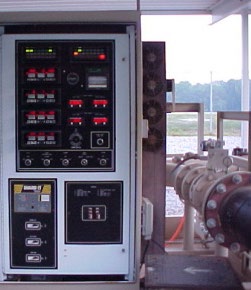
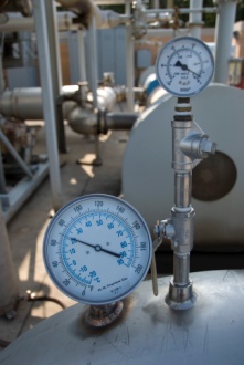
LFG Energy Project Development Handbook
Best Practices for Landfill Gas Collection System Operation and Maintenance
8-1
8. Best Practices for Landfill Gas
Collection System Operation and Maintenance
Photo credit (left): Smith Gardner, Inc.
A landfill’s gas collection system (GCS) requires frequent monitoring and operational adjustments to
optimize its performance to meet its design and operational goals. Proper operation and maintenance
(O&M) can minimize air leaks in the system and reduce the amount of time a system is taken down for
repair. Appendix A provides a series of flowcharts presenting typical wellhead monitoring procedures and
operational adjustments for oxygen, temperature, methane, flow and vacuum. In addition, proper health
and safety considerations and training are necessary to ensure the well-being of GCS operators.
This chapter provides an overview of GCS O&M best practices. GCS operators can use this information
to better understand options to ensure a well-maintained GCS to minimize surface emissions and system
downtime and ensure the health and safety of employees. Each best practice may not be suited for a
particular landfill so application must be determined on a site-specific basis. Information in this chapter
is not official guidance; rather, it provides general information about options and considerations for GCS
O&M. Landfill owners and operators are responsible for compliance with applicable regulations.
8.1
System Vacuum
Blowers provide a consistent vacuum, often measured in inches of water column (in. WC), to convey
landfill gas (LFG) from individual wells, laterals and headers to a central location for combustion in a
flare or energy recovery. Although the vacuum applied to individual wells may vary based on the function
and location of each well or collector, the vacuum should remain relatively stable over time at a given
point in the collection system. Large fluctuations in vacuum at the same collection point in the system
suggest potential concerns with condensate buildup or a blockage in the system.
Commonly, blowers use a pressure sensor and a variable frequency drive (VFD) attached to the blower to
control and stabilize the vacuum applied to the GCS. The pressure sensor measures the vacuum on the
header which, via a programmable logic controller and VFD, controls the frequency and voltage supplied
to the motor. This in turn controls the speed at which the blower impeller(s) operate. The VFD can speed
up or slow down the blower to maintain a consistent vacuum on the GCS. With such controls, technicians
can more accurately tune each well, knowing that the applied vacuum from the system is relatively
consistent. Adjustments to a well should be made in small increments and then re-monitored to assess
how those changes affect the operations. Large adjustments can lead to wide swings in operational
adjustments at the well and at adjacent extraction points.
The vacuum applied to the GCS by the blower must be sufficient to provide the furthest point of the
landfill with a minimum vacuum, typically 5 to 15 in. WC at full flow conditions. However, the vacuum
cannot be so high that it becomes difficult to tune the wellfield or compromises the condensate
management system. Systems are typically designed for a vacuum ranging from 30 to 60 in. WC or more,
depending upon the overall size and number of LFG extraction points in the wellfield. The vacuum that
LFG Energy Project Development Handbook
8-2
Best Practices for Landfill Gas Collection System Operation and Maintenance
the well applies to the waste is adjusted at each individual wellhead and must balance the need to achieve
a high gas collection efficiency to avoid odors and surface emissions, while also avoiding excessive
vacuum that can lead to air infiltration.
Control System Types
Beyond identifying and managing the physical conditions of the wellfield, it is just as important to
understand the control goals. Systems are typically set up in one of three control modes: vacuum, flow
rate or heat content (in British thermal units or Btu). The control setup is an important consideration in
wellfield operation because operators need to understand how tuning a single well can affect the rest of
the system and therefore its impact on meeting the overall objective.
•
Vacuum control – The control system maintains a constant vacuum while allowing the LFG flow rate
and heat content to vary. In this situation, vacuum at every well is controlled individually and does
not affect the vacuum at the other wells. Once a wellfield is tuned, the vacuum should stay very
stable. Vacuum control, however, requires flexibility of the end use to handle variable flows and heat
content levels.
•
Flow rate control – The site sets a desired LFG flow rate at a flow meter and the VFD maintains this
rate. In this situation, when the flow rate at an individual well is increased, the flow rate at every other
well will decrease slightly to maintain constant flow. This operating situation is not ideal and
typically occurs only for short periods of time when the system has reached a minimum or maximum
limit for the LFG end use.
•
Heat content control – This type of system is often used for landfills with an energy project and is the
most complicated system for tuning. Every time an individual well is adjusted, the flow and vacuum
for other wells in the system also change. For this reason, it is important for operators to work slowly
and make small changes. Heat content control systems are the easiest to make significant changes to
the gas quality, whether positive or negative. It is the system type typically used for beneficial-use
wellfields, because it incorporates not only parameters for regulatory compliance (i.e., vacuum
application and gas quality) but also parameters needed for an effective LFG energy recovery project,
including volumetric flow and fuel value.
Well Tuning
Operating a GCS is a balancing act of applying vacuum to a collector to obtain the largest radius of
influence possible and thus collecting as much LFG as possible, while not pulling too hard on the
collector so as to avoid air intrusion through the cover, into the waste mass and into the LFG collector.
Over-pulling (applying excess vacuum) on an LFG collector can lead to excessive oxygen in the waste
mass, which could reduce methane production or in severe cases start a subsurface oxidation event (fire).
Applying too little vacuum does not create a large enough radius of influence around the collector,
preventing overlapping radii of influence with the adjacent collectors and allowing fugitive LFG to escape
through the cover.
The operational goals of a wellfield are typically determined during the design of the GCS since the goals
of the system will influence both its design and operation. Common end goals of a GCS are:
•
Maintain compliance;
•
Generate electricity;
•
Produce medium-Btu gas; or
•
Produce renewable natural gas (RNG).
LFG Energy Project Development Handbook
Best Practices for Landfill Gas Collection System Operation and Maintenance
8-3
Because these goals have very different tuning approaches, it is difficult to meet all the goals at the same
time. However, with the primary goal in mind, operators can tune the wellfield to meet the needs of the
system as a whole.
To maintain compliance by controlling odors and gas migration, operators aim to optimize LFG
collection at each well. This may result in a small amount of atmospheric air infiltrating the surface of the
landfill during attempts to keep the entire landfill under vacuum and maximize the influence of each well.
In a typical landfill, tuning for 48 to 52 percent methane content in the LFG will result in some infiltration
of atmospheric air. Balance gas (nitrogen) may constitute 10 to 15 percent of the LFG with 0 to 2 percent
oxygen. (See Identifying Air Leaks below for additional information on this topic.)
For the purpose of collecting LFG to supply an energy generation project, it may seem appropriate to
increase the vacuum on the system as a whole or at individual wells to collect more gas on a flow basis.
However, this approach causes two problems: (1) it pulls air into the landfill, diluting the LFG that is
collected and reducing its heat content, and (2) it pulls oxygen into the waste mass, creating aerobic
conditions that are not ideal for methane production. Instead, a balanced approach of maximizing the
radius of influence without creating aerobic conditions is most effective. This often requires upgrading
cover materials, installing new gas collectors and modifying wellfield tuning procedures.
Some types of energy generation facilities or other LFG end uses require a minimum quality of gas to
meet either the contract or equipment requirements that further dictate how the system is tuned. The Solid
Waste Association of North America (SWANA) developed a range of relative methane concentration
target values based upon the goal(s) of GCS operation, as shown in Table 8-1.
Table 8-1. Example Methane Target Values
1
Target (%)
Application
50-55
Interior wells for energy recovery
45-50
Interior wells where environmental control is important
40-45
Aggressively trying to control LFG migration
30-40
Interior wells where acute LFG emission problems are occurring (but there
may be an increased risk of fires at some sites when operating in this range)
<30
Perimeter gas wells outside of refuse
Identifying Air Leaks
An air leak in a GCS is a problem that must be actively identified and repaired. Air leaks lower the gas
quality for beneficial use facilities and can also cause individual wells to underperform by diluting the
methane concentration and possibly requiring the applied vacuum to be lowered during well tuning to
meet operational goals. To quickly identify these air leaks, operators should look for 4 parts balance gas
to 1 part oxygen in all gas readings (4-to-1 ratio), the ratio of balance gas to oxygen in the atmosphere.
Nitrogen is typically not produced during the generation of LFG so any nitrogen present in a gas well has
been pulled into the system from the atmosphere. A typical well that is balanced will be operating at 2 to
10 percent nitrogen (monitored and read as balance gas), indicating that the well’s vacuum is pulling to
1
Solid Waste Association of North America. Landfill Gas Operation & Maintenance Manual of Practice, Version 1.0, revision
September 2002, Table 9.3.
LFG Energy Project Development Handbook
8-4
Best Practices for Landfill Gas Collection System Operation and Maintenance
the surface but not introducing excessive atmospheric air. The exact target for nitrogen content should be
based on the operational goal of the GCS (e.g., for compliance alone or compliance and a beneficial use
project). Nitrogen/balance gas targets assume that the air intrusion is through the waste mass and not an
air leak in the collection system itself.
Wells that are operating above 20 percent balance gas should be corrected immediately, because this can
affect the methane-producing (anaerobic) bacteria by creating aerobic conditions, thereby reducing
methane production. Additionally, the transition from an anaerobic to an aerobic environment is
exothermic (i.e., produces heat). If atmospheric air intrusion is allowed to persist, the waste mass may
begin to oxidize locally, risking a sub-surface fire. This negatively affects not only local LFG production
but also the structural integrity of the GCS and the cover system.
Ranges of residual nitrogen and their likely impacts are provided in Table 8-2. These interpretations can
be incorporated into the tuning scheme for the wellfield to increase the effectiveness of GCS operations.
Table 8-2. Interpretation of Residual Nitrogen in LFG
2
2
Solid Waste Association of North America. Landfill Gas Operation & Maintenance Manual of Practice, Version 1.0, revision
September 2002, Table 9.4.
Residual Nitrogen (%)
Interpretation
0-6
Normal to under-stressed; typical for a wellfield supporting an RNG project
where low nitrogen is desirable
6-12
Normal desirable operating range without compromises for problem areas
16-20
Excessive nitrogen, may be necessary for aggressive perimeter migration
control, side slope emission control or where other compromise is required
>20
Over-stressed; this level of nitrogen should be avoided if possible, except
for aggressive emission control
Identifying Vapor Locked Wells
Vapor locked wells are restricted by some means and do not allow for sufficient gas flow as designed.
The wells can be full of liquids or be pinched, broken, plugged or fouled and these conditions can be
identified by interpretation of collected wellfield data. Vapor locked wells have a header vacuum that is
very close to the applied vacuum because flow creates a pressure drop across the wellhead. These wells
also typically have high methane quality, showing ample LFG available but minimal flows.
Issues Due to Waste Settlement
Waste filling practices in areas of the landfill with a GCS already in place can lead to negative impacts on
the GCS from damage caused by operations or settlement. Landfills that accept large amounts of waste
tend to have more settlement of the waste mass, which can negatively impact GCS components by
creating low points in piping or blockages. Typically, the GCS at these sites may require more frequent
component inspections and a plan for replacement to maintain operational goals.
Similarly, sites that fill large flat areas across several cells gain airspace from settlement over time, but
the GCS tends to have shallow wells, laterals with minimum slopes and high liquid infiltration causing
higher GCS operational costs. In these situations, GCS components may become buried and ultimately
LFG Energy Project Development Handbook
Best Practices for Landfill Gas Collection System Operation and Maintenance
8-5
unusable. Portions of the GCS at these sites should be considered sacrificial as they may need to be
repaired or replaced multiple times during the life of the landfill.
8.2
Managing Excess Liquids in Collection System
Moisture can become a major issue for gas generation, gas collection and slope stability when it becomes
free standing liquid within the waste mass. Liquids in wells and within the landfill should be managed
and removed regularly, even at sites that are operating under a liquids recirculation plan. If wells or
lateral/header piping become flooded with liquids, they will not be able to extract the LFG and convey it
to the flare or other equipment. A variety of techniques exist to monitor for flooded wells or piping,
including simple observations to more advanced techniques.
The following general observations can indicate “watered-in” wells or piping:
•
High well vacuum but low or no flow;
•
Drops in header system vacuum from well to well;
•
Audible surging of liquids, either at individual wells or in the collection lines between the wells when
walking along the surface of the landfill.
More advanced monitoring techniques for liquids include:
•
Checking liquid levels periodically in the wells;
•
Measuring the liquid recharge rate in wells after pumping;
•
Inserting a camera down the well to identify the depth of the water or other well damage;
•
Adding submersible or “diver” dataloggers inside of problematic wells to allow a landfill operator to
continuously measure and track liquid levels.
Preventing liquids from entering the GCS is the most practical and cost-effective solution. One inch of
precipitation over an acre of exposed surface results in more than 27,000 gallons of potential liquid
infiltration. A variety of operational techniques are available to reduce surface liquids:
•
Apply alternate daily cover such as “Posi-Shell” and tarps in new cells that will not be in service for a
long time.
3
•
Consider early partial closure of areas with geomembrane. Place temporary geomembrane caps over
areas that will not receive waste for a long time and final cover on final slopes to eliminate rainwater
percolation.
4
•
Maintain a smaller and appropriately sloped working face to limit precipitation intrusion.
•
Avoid overuse of recirculation practices and consider limiting recirculation to surface spraying of
active working face.
3
Szczepanski, Mallory. 10 Tips for Preventing Landfill Leachate. July 2017.
http://www.waste360.com/leachate/10-tips-
preventing-landfill-leachate/gallery?slide=5
.
4
Szczepanski, Mallory. 10 Tips for Preventing Landfill Leachate. July 2017.
http://www.waste360.com/leachate/10-tips-
preventing-landfill-leachate/gallery?slide=2
.
LFG Energy Project Development Handbook
8-6
Best Practices for Landfill Gas Collection System Operation and Maintenance
Pumps
In some cases, pumping will be required, despite efforts to minimize surface water or other liquids from
entering the landfill. Many systems employ pump systems within individual LFG extraction wells to
reduce local zones of waste saturation and improve the operations of individual LFG collectors. Because
LFG wells are typically the most permeable components within the waste mass, liquids tend to
accumulate in these locations.
When liquids accumulate in wells, the elevated liquid levels within the well casing diminish the efficiency
of the extraction well. As the liquid level rises within the perforated casing section, vacuum is applied to
an increasingly smaller volume of waste. This not only reduces the potential volume of LFG that can be
recovered from an individual well, but also increases the potential for air intrusion since more vacuum is
applied to the top of the perforated casing section.
Pneumatic pumps are typically used to remove liquids from LFG extraction wells. They provide a slow
(less than 2 gallons per minute), steady rate of withdrawal over a wide range of discharge head
requirements. By using a slow withdrawal rate, the operator limits the potential for fouling the backfill by
keeping the liquid velocity relatively low as it travels through the waste mass, thereby limiting the ability
of the flowing fluid to carry fine particles.
Monitoring of the liquid levels, along with comparisons of changes in LFG recovery performance, should
be continued on at least a monthly basis until a steady-state condition is achieved. Pumping may be
required for an extended period of time, depending upon the degree of local waste saturation and re-
charge from precipitation or other liquid addition. If a “maintenance level” of liquid can be achieved that
does not require additional pumping, the pumping equipment may be removed for another installation.
Air Compressors
A pneumatic pumping system requires air compressors designed for continuous, industrial applications.
Air compressors for LFG applications are typically oil-free screw compressors with relatively large
receivers. The compressed air must also be conditioned to avoid filling the compressed air mains with
condensate from the compression process. This requires an industrial-level air dryer and filtration system
to maintain a usable air supply. Laboratory-quality compressed air is not required, however a uniform and
“clean” air supply will increase the reliability of the pumping system and reduce costly maintenance of
both the compressed air supply system as well as pumping components.
If the GCS includes pneumatic components that are critical for GCS operation, such as fail-close valves
and a condensate management system at the blower station, then a backup or segregated compressed air
system or the use of compressed nitrogen for emergency purposes may be necessary.
8.3
GCS Monitoring
A robust and proactive monitoring system, consisting of both physical inspection and analytical data
collection techniques, can detect operational problems early and minimize system downtime. State and
federal rules prescribe certain monitoring of a GCS, which should be viewed as minimum requirements.
State or federal wellhead monitoring requirements may include:
•
Surface emissions monitoring for methane;
•
Vacuum present at the wellhead (i.e., less
than 0.0 in. WC);
•
Oxygen and nitrogen content; and
•
Wellhead temperature.
LFG Energy Project Development Handbook
Best Practices for Landfill Gas Collection System Operation and Maintenance
8-7
For relatively high wellhead temperature readings (i.e., above 62.8
o
C (145
o
F)), federal rules require
enhanced monitoring of other parameters including visual observations for subsurface fires, carbon
monoxide content and methane content. For higher wellhead temperatures (i.e., above 73.9
o
C (165
o
F)),
federal rules require monitoring of temperature down in the well in addition to the wellhead temperature.
Exceptions may apply to these thresholds in certain cases, such as when there is concern that applying
vacuum to a well may exacerbate conditions where a subsurface fire is suspected. Additionally, positive
pressure may be allowed in areas with a geomembrane or synthetic cover, provided that engineering
calculations have been performed to determine the amount of allowable pressure that will not pose a risk
of uplift and cap failure. Finally, these requirements may not apply to wells that have been permanently
decommissioned, if LFG continues to be collected in the area.
Variances, in the form of higher operating values or alternative operating parameters may also be
requested for approval to allow operating wells at higher temperatures. These requests must be supported
by sufficient data to demonstrate that higher values will not pose a risk of subsurface fire or inhibit the
production of methane.
In addition to minimum regulatory parameters above, flow rate should be monitored at all wellheads. A
well may be under vacuum but not collecting any gas if leachate or condensate is covering the perforated
zone. Total system flow and gas quality at the header should be monitored as well, as significant changes
in header flow or quality can alert operators to issues in the wellfield that warrant investigation.
Closed landfills with final cover and a fully built-out GCS do not generally require the same level of
attention as an active landfill and may be monitored on a monthly basis at a minimum. Voluntarily
operated systems at a closed landfill may be monitored less frequently, although monthly monitoring
continues to be recommended. Active landfills with partially installed systems may require more frequent
monitoring. These systems are more susceptible to impacts from moisture (e.g., precipitation, leachate
recirculation) due to potentially large areas of active filling and/or intermediate cover as well as air
infiltration. Gas flow rates and quality may also vary due to atmospheric pressure changes. Additionally,
waste filling operations may damage collection wells in active filling areas, requiring repair.
For wellfields supporting an energy recovery project, more frequent monitoring is generally
recommended due to the financial incentive to maximize methane flow, not just LFG flow. Energy
projects producing RNG require the highest level of wellfield tuning, to minimize air infiltration to the
maximum extent possible.
Wellfield data should be collected and maintained in a database following each monitoring activity.
Landfills with mandatory GCS operational requirements have as few as five days to initiate corrective
action on wells exceeding certain compliance parameters, so early detection is critical. These data should
be maintained for a minimum of five years, in order to observe trends over time and understand the
impacts of GCS or landfill operations on gas generation and collection over time. For example, a landfill
that recirculates leachate may experience a faster generation rate of LFG, as well as a more rapid decline,
than predicted by LFG modeling.
Databases for wellfield data may be simple spreadsheets or data reporting tools included in many office
software packages such as Microsoft® Excel or Access. Data may be filtered or sorted to view changing
conditions and trends by wellhead over time, such as declining flow rates or increasing temperatures.
Wellhead vacuum can be compared to header vacuum to identify wells that may be “watered-in.”
Conditional formatting within spreadsheets can help identify regulatory exceedances at a glance. Landfills
with a larger, complex GCS may benefit from more robust data management software packages. These
solutions may include Geographic Information Systems (GIS) functionality to generate maps depicting
LFG Energy Project Development Handbook
8-8
Best Practices for Landfill Gas Collection System Operation and Maintenance
areas of high temperature, declining methane or other operational concerns. Automated graphing and
report generation may be included as options for some of these packages to facilitate wellfield data
trending and evaluation.
In addition to gas flow and quality trends over time, monitoring data can be used to identify unintended
subsurface conditions in landfills that that may be caused in part by GCS operations, including subsurface
reactions and subsurface oxidations (fires).
Subsurface reactions are seen in landfills where relatively deeper, wetter areas of waste experience an
interruption in the anaerobic production of methane. These conditions tend to cause heat accumulation
and inhibit methane production. Certain waste types, including ash and metals, may react exothermically
as they corrode to produce additional heat. Rapid dewatering of deep wells may inadvertently introduce
oxygen to the surrounding waste mass, further upsetting the anaerobic conditions. This subsurface
reaction, not to be confused with subsurface combustion, forms products seen in the early aerobic stages
of waste degradation, including fatty acids and hydrogen. These reactions also form positive pressure and
carbonation of leachate in the well, leading to wellheads “popping off” and leachate foaming. Rapid
localized settlement of several feet may occur around one or multiple wells during these reactions. In
addition to enhanced monitoring requirements under regulations, monitoring data, including LFG
collection for lab analysis, may indicate that a subsurface reaction is occurring. These data include:
•
Elevated temperature;
•
Low methane-to-carbon dioxide ratio;
•
Positive well pressure;
•
Well foaming;
•
Low oxygen;
•
High hydrogen levels;
•
High ammonia levels; and
•
Rapid localized settlement around one or
several wells.
Hydrogen and ammonia may be read as balance gas and assumed to be nitrogen. Gas samples will need to
be collected for laboratory analysis to confirm their presence.
Subsurface fires occur when waste below the landfill surface undergoes combustion. These combustion
events may occur when air is introduced into the waste mass as a result of wells placed under excess
vacuum, commonly referred to as “over-pulling.” These events typically occur from just under the landfill
surface to depths of as much as 15 to 20 feet. Parameters that may indicate subsurface fires include:
•
High temperature;
•
Low methane-to-carbon dioxide ratio;
•
Carbon monoxide;
•
Visible smoke or discoloration of flexible
wellhead hose from heat/smoke;
•
Air infiltration and aerobic conditions in
waste; and
•
Rapid localized settlement around one or
several wells.
Subsurface reactions and subsurface fires may exhibit some of the same parameters. Thus, it is important
to collect as much data as possible and evaluate all parameters together.
Emerging technologies may improve wellfield operations and improve LFG collection. Remote
monitoring of LFG flow rates and quality through telemetry and other methods have been proven
technologies at flares and blower skids for several years. In recent years, technologies have been
developed to remotely monitor LFG flow rate and gas quality in header pipes and individual gas wells
using sensors and radio or cellular transmitters to relay the data to a cloud-based data server. Remotely
actuated valves may be installed to control vacuum and flow rates at the individual wellhead based on


LFG Energy Project Development Handbook
Best Practices for Landfill Gas Collection System Operation and Maintenance
8-9
direct operator input, setpoints for various parameters or complex algorithms which attempt to balance
multiple parameters. As of May 2021, approximately 24 U.S. MSW landfills have remote header or well
monitoring technologies installed. The objective of these efforts is to reduce costly labor and optimize
LFG flow rates and boost overall methane yields. Due to initial capital cost, ongoing maintenance related
to sensor replacement and programming, adoption of these technologies is limited and primarily confined
to larger landfills able to generate revenue from LFG energy projects. However, some landfills have also
employed this technology for odor management.
Emerging technologies have also improved options available to landfills for completing methane surface
emissions monitoring requirements, identifying leaks more efficiently and reducing exposures and other
health and safety risks for monitoring personnel. New monitor and methane sensor technologies reduce
the need to use flammable hydrogen fuel to operate the traditional toxic vapor analyzer monitors. In
addition, research with aircraft-based, drone-based and satellite-based sensor technologies is being
conducted to detect fugitive methane emissions at landfills. EPA hosted a
Landfill Surface Emissions
Monitoring and Measurement Virtual Workshop
in January 2021 to share information about emerging
monitoring and measuring technologies for MSW landfills.
8.4
Health and Safety
Every employee is
responsible for his or her
own safety, as well as the
safety of those around them.
There are many details associated with GCS health and safety
through industry guidance as well as Occupational Safety and
Health Administration (OSHA) and National Fire Protection
Association (NFPA) requirements for various activities.
Personnel working with a GCS should be aware of any site-
specific health and safety requirements, including the site-
specific Health and Safety Plan (HASP).
Although a comprehensive safety review encompassing all potential impacts is not provided in this
document, there are several general items applicable to all GCS facilities, listed below. This list is
intended to be an overview and does not take the place of a HASP developed by a trained safety
professional. Additional guidance can be obtained from SWANA’s
Landfill Gas Operation &
Maintenance Manual of Practice
5
and other industry publications.
5
Solid Waste Association of North America. Landfill Gas Operation & Maintenance Manual of Practice, Version 1.0, revision
September 2002.
1.
Do not smoke or allow other sources of ignition within 25 feet of any source of LFG, including LFG
components and portions of the leachate and condensate management systems.
2.
Use a personal combustible gas meter when working around any GCS components. Meters should
have a minimum capability of monitoring for oxygen-deficient conditions, carbon monoxide
concentrations and methane concentrations.
3.
Understand the potential hazards of working in proximity to LFG and LFG condensate.
4.
Wear appropriate personal protective equipment (PPE) for all tasks and be aware of the relative
limitation of each level of PPE. Level D is the minimum requirement.
5.
Make sure that all PPE is in good, working condition.
6.
Make sure that all monitoring equipment is fully charged and calibrated per manufacturer’s
requirements.
LFG Energy Project Development Handbook
8-10
Best Practices for Landfill Gas Collection System Operation and Maintenance
7.
Verify that all pressures are relieved, and that any potential sources of pressurization are de-energized
or locked out, before opening any vessels.
8.
Always comply with mechanical, electrical, pneumatic and hydraulic lock-out/tag-out procedures.
9.
Have personnel trained to identify and work in permit-required confined spaces.
10.
Have personnel trained to identify trenching and excavation activities compliant with OSHA
requirements.
11.
Never leave open excavations (including well bore holes) unmarked, unsecured or unattended,
including the use of grates during well drilling, setting casings, backfilling and well completion.
12.
Understand the hazards of working in proximity to flares and associated combustion systems.
13.
Understand the hazards of working in proximity to rotating equipment, including blowers,
compressors and pumps.
LFG Energy Project Development Handbook
A-1
Appendix A
Typical Wellhead Monitoring Procedures and Operational
Adjustments for Oxygen, Temperature, Methane, Flow and Vacuum

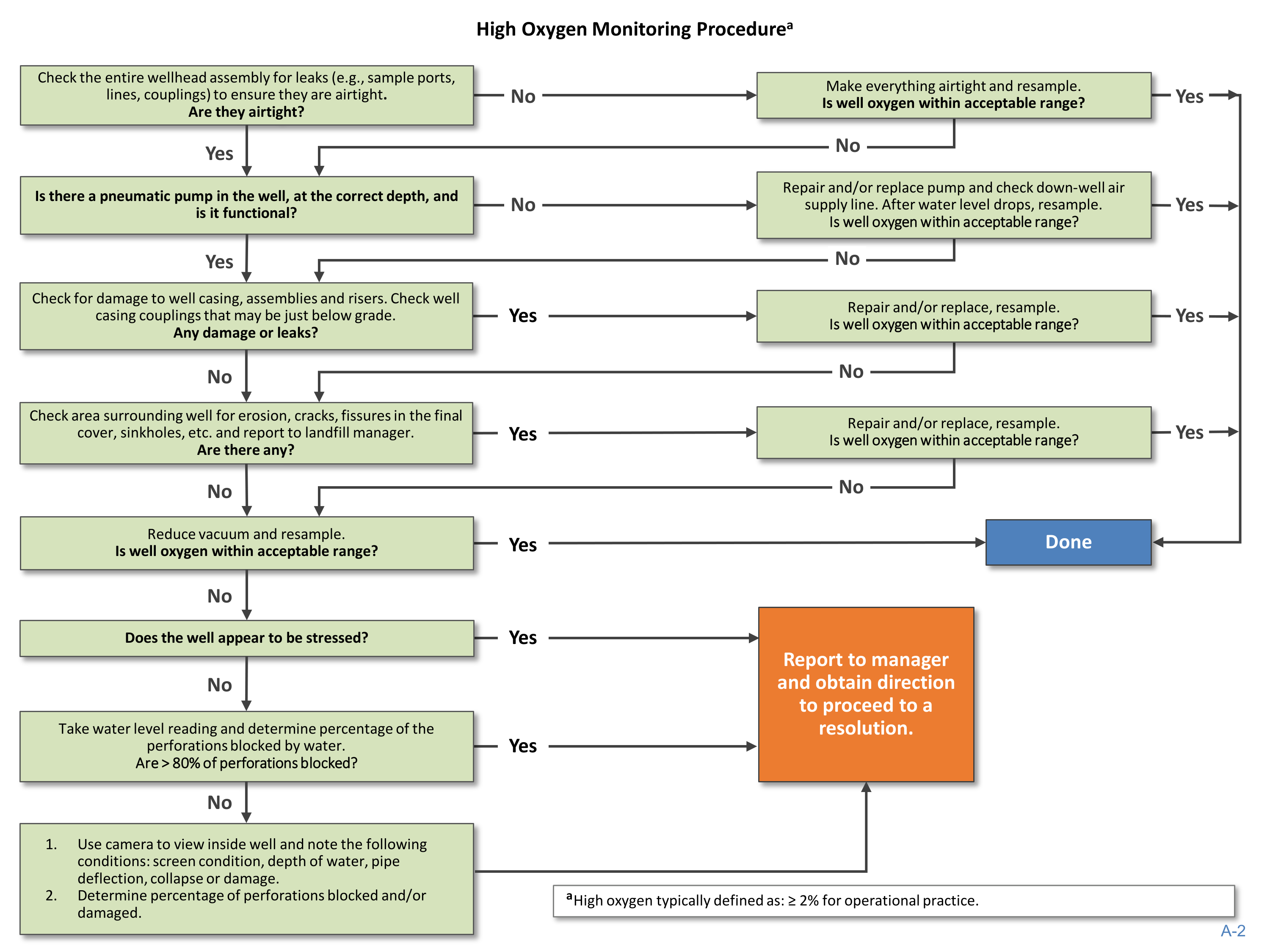





























High Oxygen Monitoring Procedure
a
Check the entire wellhead assembly for leaks (e.g., sample ports,
lines, couplings) to ensure they are airtight
.
Are they airtight?
No
Make everything airtight and resample.
Is well oxygen within acceptable range?
Yes
Is there a pneumatic pump in the well, at the correct depth, and
is it functional?
No
Repair and/or replace pump and check down-well air
supply line. After water level drops, resample.
Is well oxygen within acceptable range?
Yes
Check for damage to well casing, assemblies and risers. Check well
casing couplings that may be just below grade.
Any damage or leaks?
Yes
Repair and/or replace, resample.
Is well oxygen within acceptable range?
No
Yes
Repair and/or replace, resample.
Is well oxygen within acceptable range?
No
Reduce vacuum and resample.
Is well oxygen within acceptable range?
Yes
Done
No
Does the well appear to be stressed?
Yes
No
Take water level reading and determine percentage of the
perforations blocked by water.
Are > 80% of perforations blocked?
No
1.
Use camera to view inside well and note the following
conditions: screen condition, depth of water, pipe
deflection, collapse or damage.
2.
Determine percentage of perforations blocked and/or
damaged.
Yes
Report to manager
and obtain direction
to proceed to a
resolution.
No
No
No
Yes
Yes
Yes
Yes
No
a
High oxygen typically defined as: ≥ 2% for operational practice.
Check area surrounding well for erosion, cracks, fissures in the final
cover, sinkholes, etc. and report to landfill manager.
Are there any?
A-
2
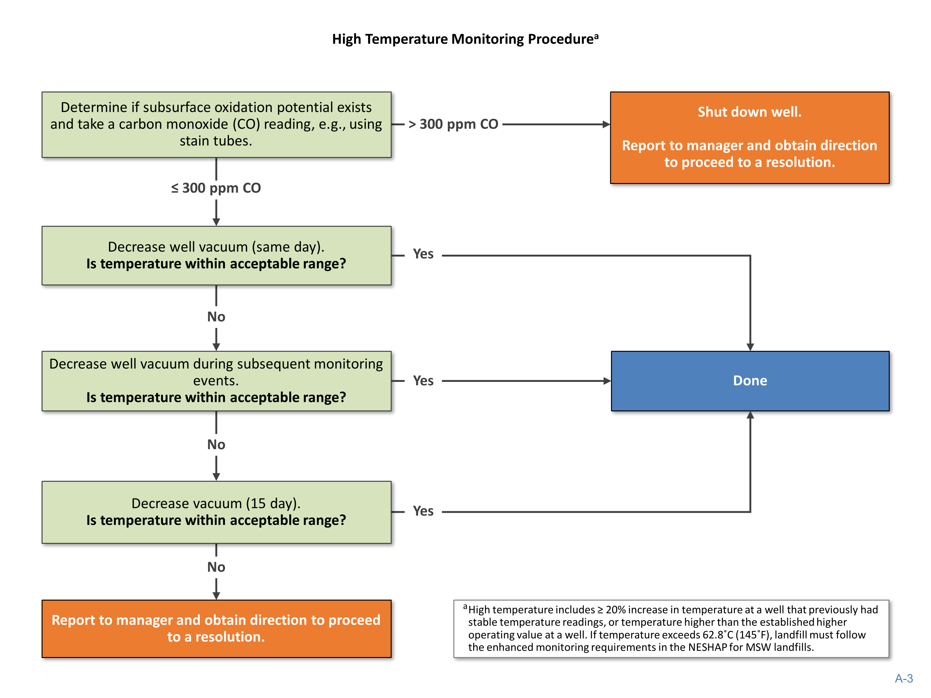















High Temperature Monitoring Procedure
a
Determine if subsurface oxidation potential exists
and take a carbon monoxide (CO) reading, e.g., using
stain tubes.
> 300 ppm CO
Shut down well.
Report to manager and obtain direction
to proceed to a resolution.
≤ 300 ppm CO
Decrease well vacuum (same day).
Is temperature within acceptable range?
No
Decrease well vacuum during subsequent monitoring
events.
Is temperature within acceptable range?
No
Decrease vacuum (15 day).
Is temperature within acceptable range?
No
Report to manager and obtain direction to proceed
to a resolution.
Done
Yes
Yes
a
High temperature includes ≥ 20% increase in temperature at a well that previously had
stable temperature readings, or temperature higher than the established higher
operating value at a well. If temperature exceeds 62.8˚C (145˚F), landfill must follow
the enhanced monitoring requirements in the NESHAP for MSW landfills.
Yes
A-
3
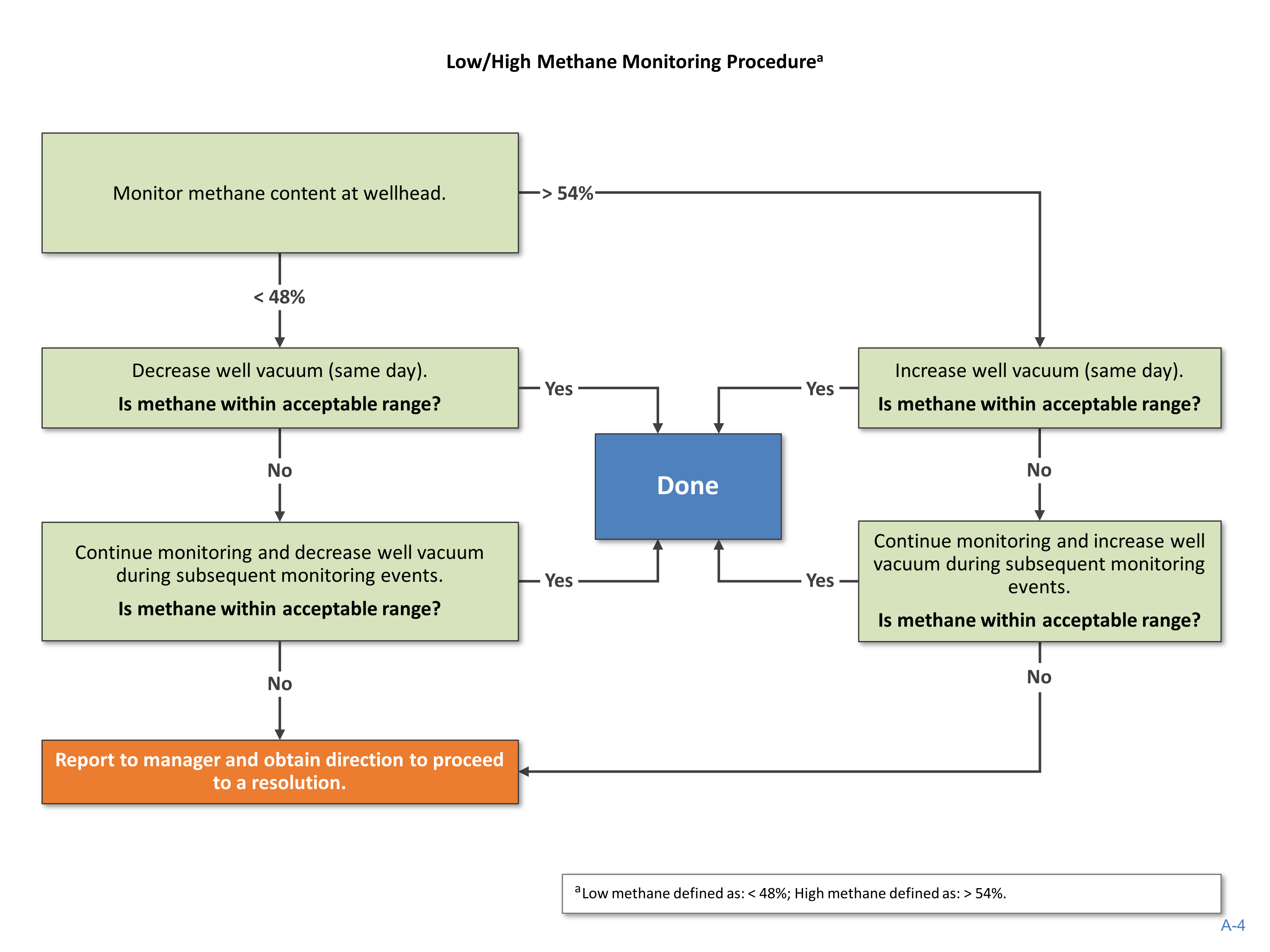














Low/High Methane Monitoring Procedure
a
Monitor methane content at wellhead.
> 54%
Increase well vacuum (same day).
Is methane within acceptable range?
No
Continue monitoring and increase well
vacuum during subsequent monitoring
events.
Is methane within acceptable range?
No
Report to manager and obtain direction to proceed
to a resolution.
< 48%
Decrease well vacuum (same day).
Is methane within acceptable range?
No
Continue monitoring and decrease well vacuum
during subsequent monitoring events.
Is methane within acceptable range?
Yes
Done
No
Yes
Yes
Yes
a
Low methane defined as: 54%.
A-
4
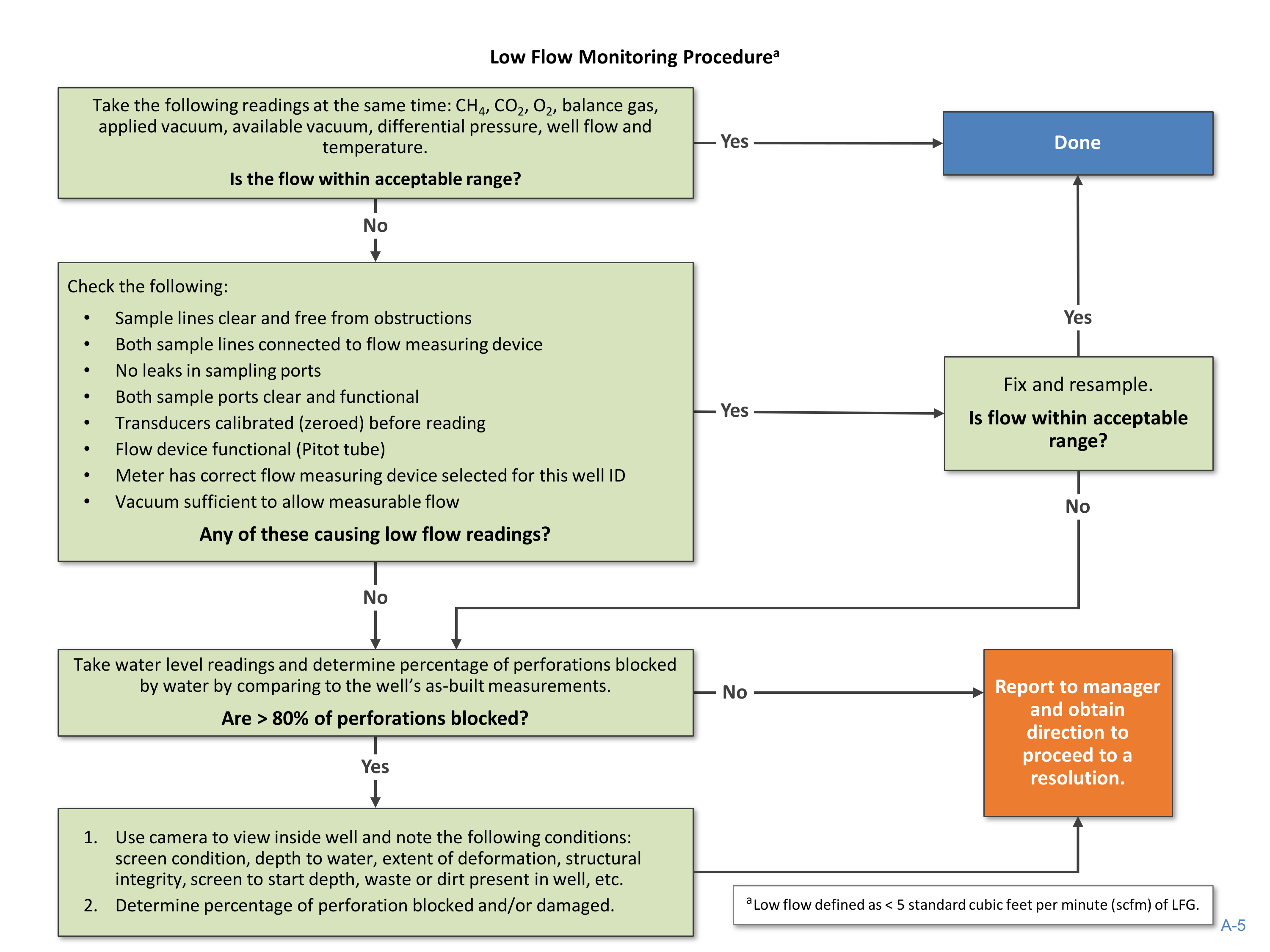
















Take the following readings at the same time: CH
4
, CO
2
, O
2
, balance gas,
applied vacuum, available vacuum, differential pressure, well flow and
temperature.
Is the flow within acceptable range?
Yes
Low Flow Monitoring Procedure
a
Done
No
Check the following:
•
Sample lines clear and free from obstructions
•
Both sample lines connected to flow measuring device
•
No leaks in sampling ports
•
Both sample ports clear and functional
•
Transducers calibrated (zeroed) before reading
•
Flow device functional (Pitot tube)
•
Meter has correct flow measuring device selected for this well ID
•
Vacuum sufficient to allow measurable flow
Any of these causing low flow readings?
Yes
Fix and resample.
Is flow within acceptable
range?
No
Take water level readings and determine percentage of perforations blocked
by water by comparing to the well’s as-built measurements.
Are > 80% of perforations blocked?
No
Report to manager
and obtain
direction to
proceed to a
resolution.
Yes
1.
Use camera to view inside well and note the following conditions:
screen condition, depth to water, extent of deformation, structural
integrity, screen to start depth, waste or dirt present in well, etc.
2.
Determine percentage of perforation blocked and/or damaged.
No
Yes
a
Low flow defined as < 5 standard cubic feet per minute (scfm) of LFG.
A-
5
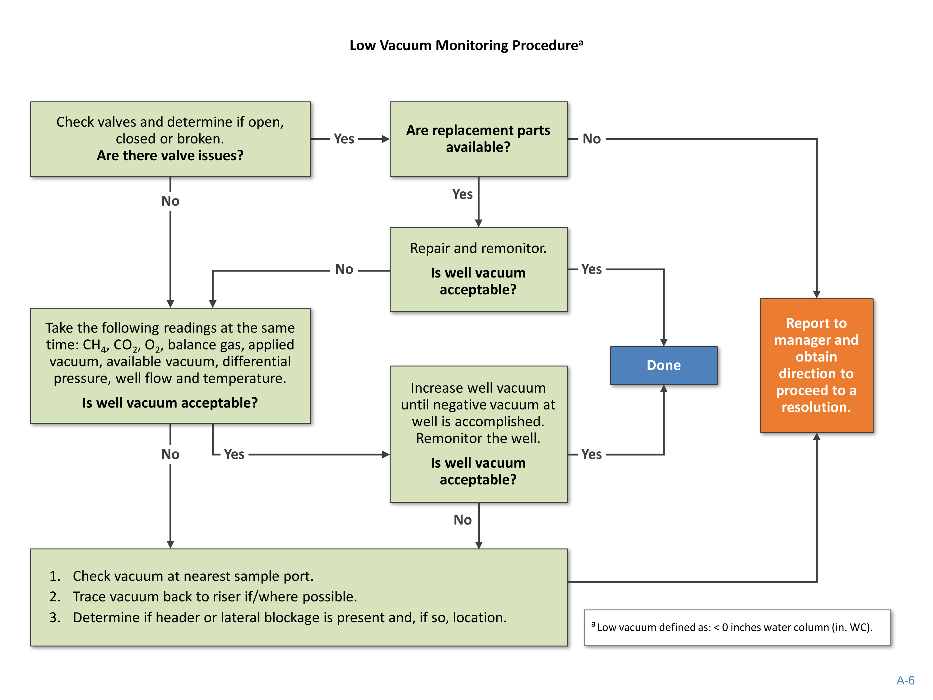

















Low Vacuum Monitoring Procedure
a
Check valves and determine if open,
closed or broken.
Are there valve issues?
Yes
Are replacement parts
available?
No
Report to
manager and
obtain
direction to
proceed to a
resolution.
No
Take the following readings at the same
time: CH
4
, CO
2
, O
2
, balance gas, applied
vacuum, available vacuum, differential
pressure, well flow and temperature.
Is well vacuum acceptable?
No
Repair and remonitor.
Is well vacuum
acceptable?
Done
Yes
Increase well vacuum
until negative vacuum at
well is accomplished.
Remonitor the well.
Is well vacuum
acceptable?
No
1.
Check vacuum at nearest sample port.
2.
Trace vacuum back to riser if/where possible.
3.
Determine if header or lateral blockage is present and, if so, location.
Yes
Yes
Yes
No
a
Low vacuum defined as: < 0 inches water column (in. WC).
A-
6


www.epa.gov/lmop/landfill-gas-energy-project-development-handbook