
Airbus technical magazine
#65
FAST
April 2020
Flight Airworthiness Support Technology
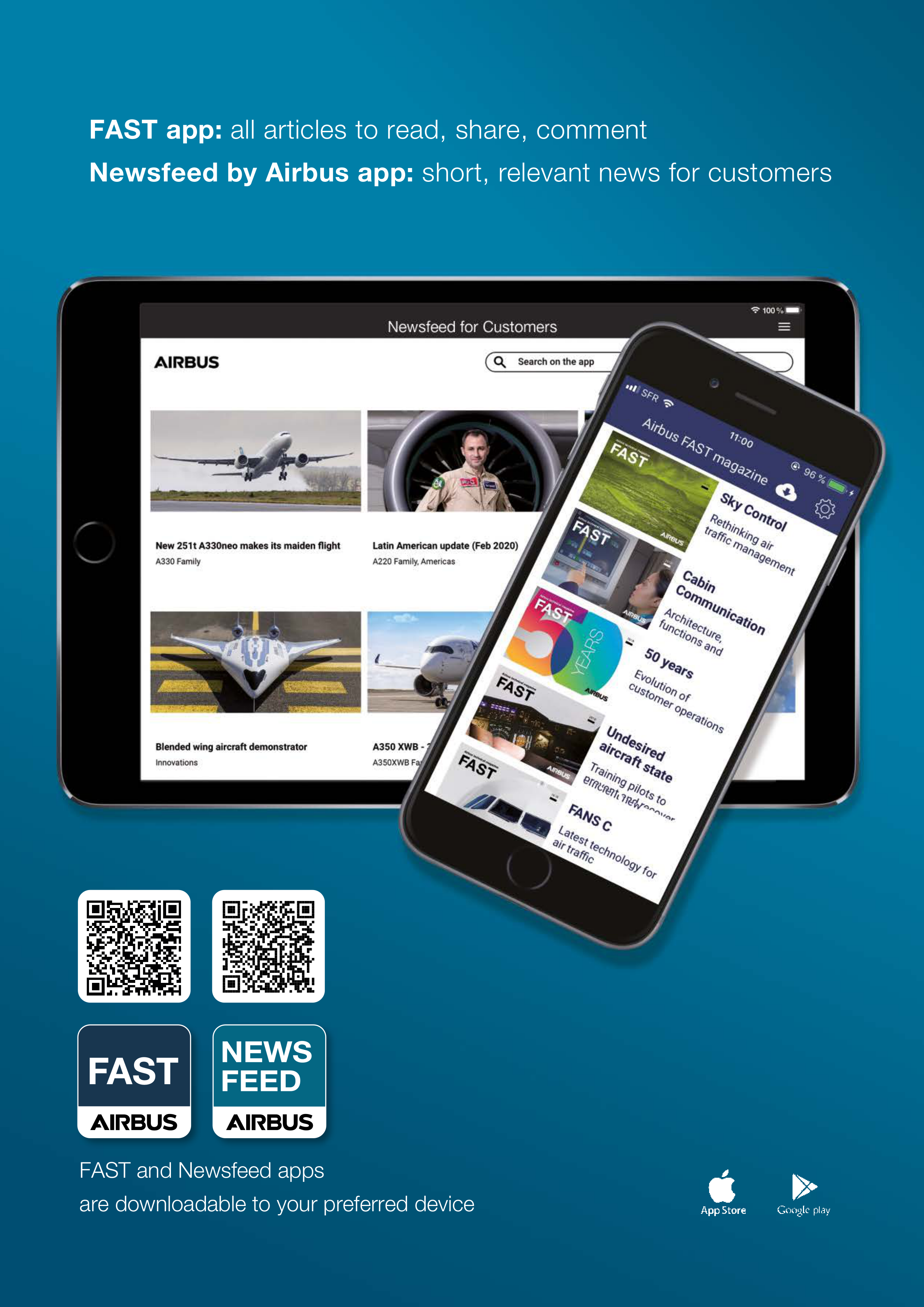
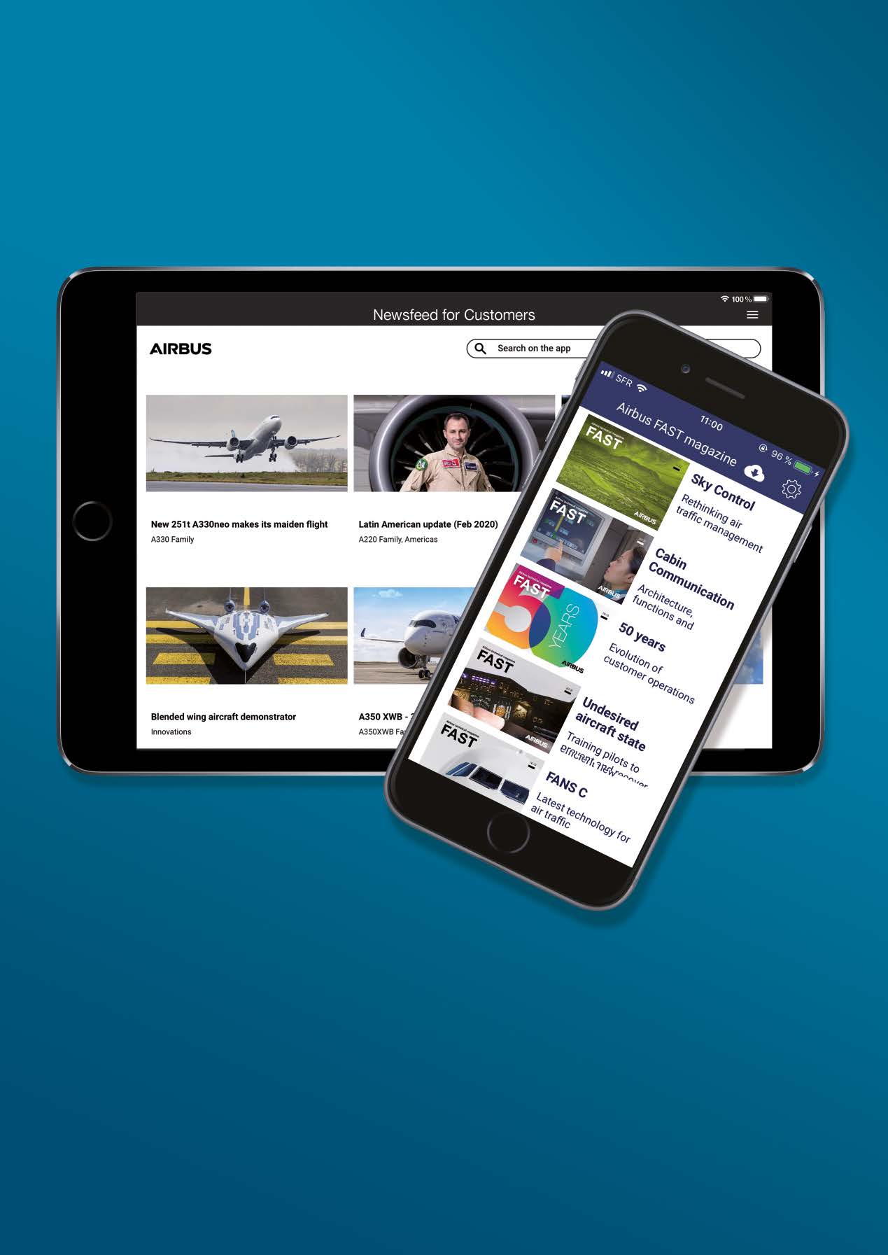





FAST and Newsfeed apps
are downloadable to your preferred device
FAST app:
all articles to read, share, comment
Newsfeed by Airbus app:
short, relevant news for customers
FAST








03 FAST#65 - 2020
© AIRBUS 2020 All rights reserved. Proprietary document
By taking delivery of this Magazine (hereafter ‘Magazine’), you accept on behalf
of your company to comply with the following. No other property rights are granted
by the delivery of this Magazine than the right to read it, for the sole purpose of
information. This Magazine, its content, illustrations and photos shall not be modified
nor reproduced without prior written consent of Airbus. This Magazine and the
materials it contains shall not, in whole or in part, be sold, rented, or licensed to any
third party subject to payment or not. This Magazine may contain market-sensitive
or other information that is correct at the time of going to press. This information
involves a number of factors which could change over time, affecting the true public
representation. Airbus assumes no obligation to update any information contained in
this document or with respect to the information described herein. The statements
made herein do not constitute an offer or form part of any contract. They are based on
Airbus information and are expressed in good faith but no warranty or representation
is given as to their accuracy. When additional information is required, Airbus can be
contacted to provide further details. Airbus shall assume no liability for
any damage in connection with the use of this Magazine and the materials it contains,
even if Airbus has been advised of the likelihood of such damages. This licence
is governed by French law and exclusive jurisdiction is given to the courts and tribunals
of Toulouse (France) without prejudice to the right of Airbus to bring proceedings for
infringement of copyright or any other intellectual property right in any other court of
competent jurisdiction. Airbus, its logo, A220, A300, A310, A318, A319, A320, A321,
A330, A340, A350, A380 and A400M are registered trademarks.
This brochure is printed on paper produced in factories that are accredited EMAS and certified
ISO 9001-14001, PEFC and FSC CoC.
It is produced using pulp that has been whitened without either chlorine or acid. The paper is
entirely recyclable and is produced from trees grown in sustainable forest resources.
The printing inks use organic pigments or minerals. There is no use of basic dyes or dangerous
metals from the cadmium, lead, mercury or hexavalent chromium group.
Photo copyright Airbus. Photo credits: Airbus Photographic Library, Airbus Corporate Heritage,
Aerotheque, Shutterstock, Master Films, A. Tchaikovski, Hervé Gousset, Philippe Masclet,
Benjamin Mouchet, Pierre-Jean Argaud, Alexandre Doumanjou, Frederick Lancelot, Sylvain
Ramadier, Pascal Pigeyre, Anthony Pecch, J. Vuillei. JF Bramard/Cambulle, D. Brillaud
,
G.Fraysse, Lindner Photographie, Boone Rodriguez
• Chief Editor: Deborah Buckler
• Writing support:
- Beetroot: Tom Whitney,
- Parkinson Stephens Editorial:
Ed Parkinson, Kate Redfern, Geoff Poulton
• Design: Pont Bleu
• Cover images: A. Tchaikovski and H. Gousset, Master Films
• Printer: Amadio
• Authorisation for reprinting FAST magazine articles:
fast.magazine@airbus.com
FAST magazine availability:
On the FAST app (see QR code opposite page)
Airbus website:
www.aircraft.airbus.com/support-services/publications/
ISSN 1293-5476
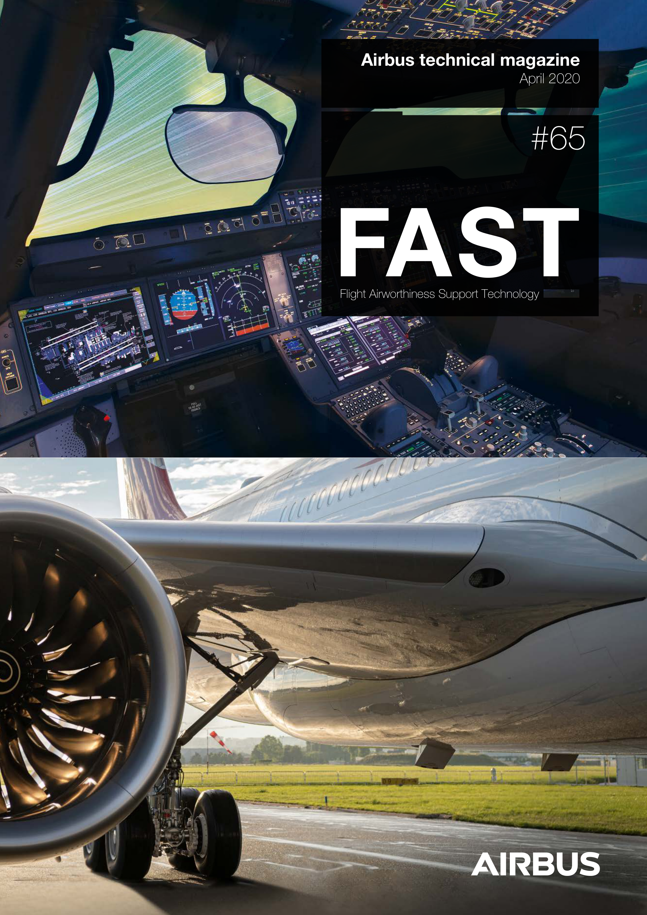
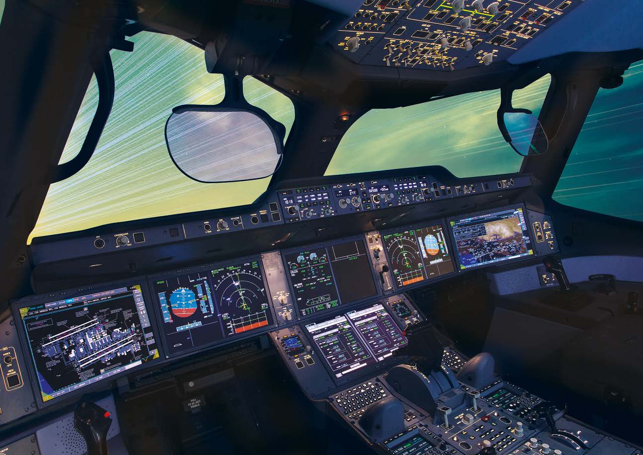
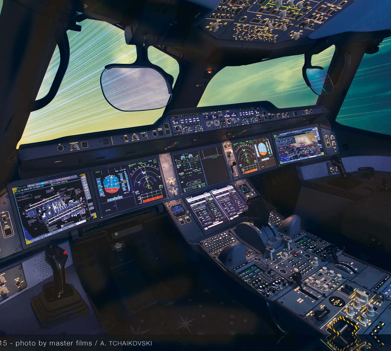
Cover photo: A350 cockpit
FAST
F
light
A
irworthiness
S
upport
T
echnology
Airbus technical magazine
#65
Propulsion system
integration
From design to entry-into-service
The defining moment
Making it easier to choose
cabin options
State-of-the-art
cockpit upgrade
The UPS choice for its A300-600 fleet
Protecting precious assets
Parking and storing aircraft
FAST forward
Innovations shaping the future
FAST from the past
Around the clock,
around the world
Customer Services contacts
and training centres
04
14
26
20
32
34
35
FAST magazine articles, primarily dedicated to Airbus
commercial aircraft customers, are written by technical
experts and focus on what is informative and useful.
Learn about innovations and evolutions to Airbus
aircraft, as well as best practices to help optimise
fleet performance. And see where Airbus is working,
sometimes with key players in the industry, to continue
to support customers and prepare the future.
Switching to the FAST app will enable you to share
and comment. Any changes in preference can be
sent to your field service or to the editor.
And for short news updates for customers, get the
Newsfeed by Airbus app (see opposite).


04 FAST#65 - 2020
Propulsion system
integration
The propulsion systems have a major impact
on an aircraft’s safety and on its environmental
and economic performance. These are key
criteria for the operator. From design to entry-
into-service, integrating the propulsion system
requires a multidisciplinary approach and close
cooperation between Airbus and its suppliers.
Article by (left to right)
Rüdiger THOMAS
Powerplant Executive Expert
AIRBUS
rudiger.thomas@airbus.com
Thierry BOUISSET
Senior Powerplant Architect
AIRBUS
thierry.bouisset@airbus.com
From design to entry-into-service








05 FAST#65 - 2020
Creating an aircraft engine: a journey
from pre-development to entry-into-service
The propulsion system – including the engines, nacelles and pylons, and the controls
integrated into the aircraft – has a significant impact on the aircraft safety, its economic
performance as well as its environmental and acoustic efficiency. Fuel burn, for example,
makes up 40-50% of an aircraft’s cash operating cost. Operational performance, reliability
and direct maintenance costs must also be taken into consideration. This makes engine
manufacturers a natural partner in aircraft development, who provide valuable input from
a very early stage.
Airbus regularly studies architecture and technology options with engine manufacturers
as part of its product strategy investigations. Before launching a new programme, a joint
study will enter a decisive pre-development phase, which will define the following aspects:
• Choice of propulsion architecture, including turbomachine and nacelle
• Engine integration, including mounting concepts, aerodynamics and aircraft systems
such as electrical, pneumatic and hydraulic systems and avionics
• Aircraft and engine optimisation to achieve the right balance between take-off
performance, climb and cruise performance, as well as acoustics
Once the key characteristics are settled, Airbus involves the nacelle manufacturer
in a three-way discussion with the engine manufacturer to finalise the overall concept
for the integrated propulsion system.
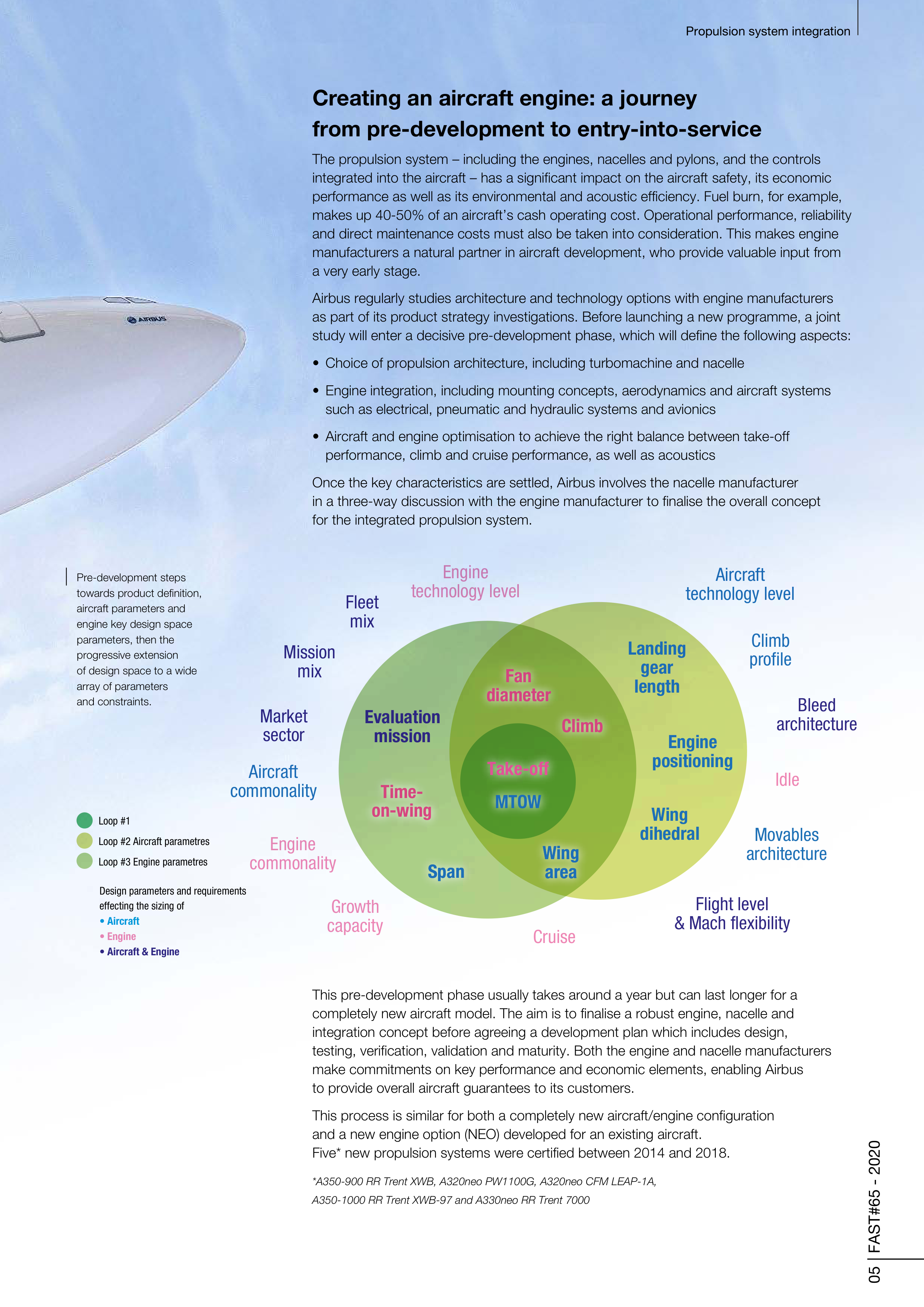
This pre-development phase usually takes around a year but can last longer for a
completely new aircraft model. The aim is to finalise a robust engine, nacelle and
integration concept before agreeing a development plan which includes design,
testing, verification, validation and maturity. Both the engine and nacelle manufacturers
make commitments on key performance and economic elements, enabling Airbus
to provide overall aircraft guarantees to its customers.
This process is similar for both a completely new aircraft/engine configuration
and a new engine option (NEO) developed for an existing aircraft.
Five* new propulsion systems were certified between 2014 and 2018.
*A350-900 RR Trent XWB, A320neo PW1100G, A320neo CFM LEAP-1A,
A350-1000 RR Trent XWB-97 and A330neo RR Trent 7000
Propulsion system integration
Fleet
mix
Mission
mix
Market
sector
Aircraft
commonality
Engine
commonality
Growth
capacity
Cruise
Flight level
& Mach flexibility
Movables
architecture
Idle
Bleed
architecture
Climb
profile
Aircraft
technology level
Engine
technology level
Climb
Time-
on-wing
Span
Wing
area
Fan
diameter
Climb
Evaluation
mission
Time-
on-wing
Span
Wing
area
Wing
dihedral
Landing
gear
length
Engine
positioning
Fan
diameter
Loop #1
Loop #2 Aircraft parametres
Loop #3 Engine parametres
Design parameters and requirements
effecting the sizing of
• Aircraft
• Engine
• Aircraft & Engine
MTOW
Take-off
Pre-development steps
towards product definition,
aircraft parameters and
engine key design space
parameters, then the
progressive extension
of design space to a wide
array of parameters
and constraints.
06 FAST#65 - 2020
Mastering extremes through
development and verification
After all conditions are met, the next phase begins, with the focus on achieving the optimum time to
market to satisfy customer needs. During a ‘make or buy’ analysis, Airbus will decide which components
it produces in-house and which to source. Supplier selection starts early on for key systems including the
engines, and can be completed later for shorter lead-time components.
Preliminary and critical design reviews are key milestones in defining the final design. Indeed, in a first
step, key functions and physical interfaces are defined and these data are shared with the stakeholders.
The design freeze is validated by the critical design reviews which fix the definitions of the engine, nacelle,
pylon and various systems and their interfaces, as well as the performance of the integrated propulsion
system and the associated means of verification. After these have been agreed, the suppliers begin
manufacturing, including the tooling and the parts needed to build the first prototypes.
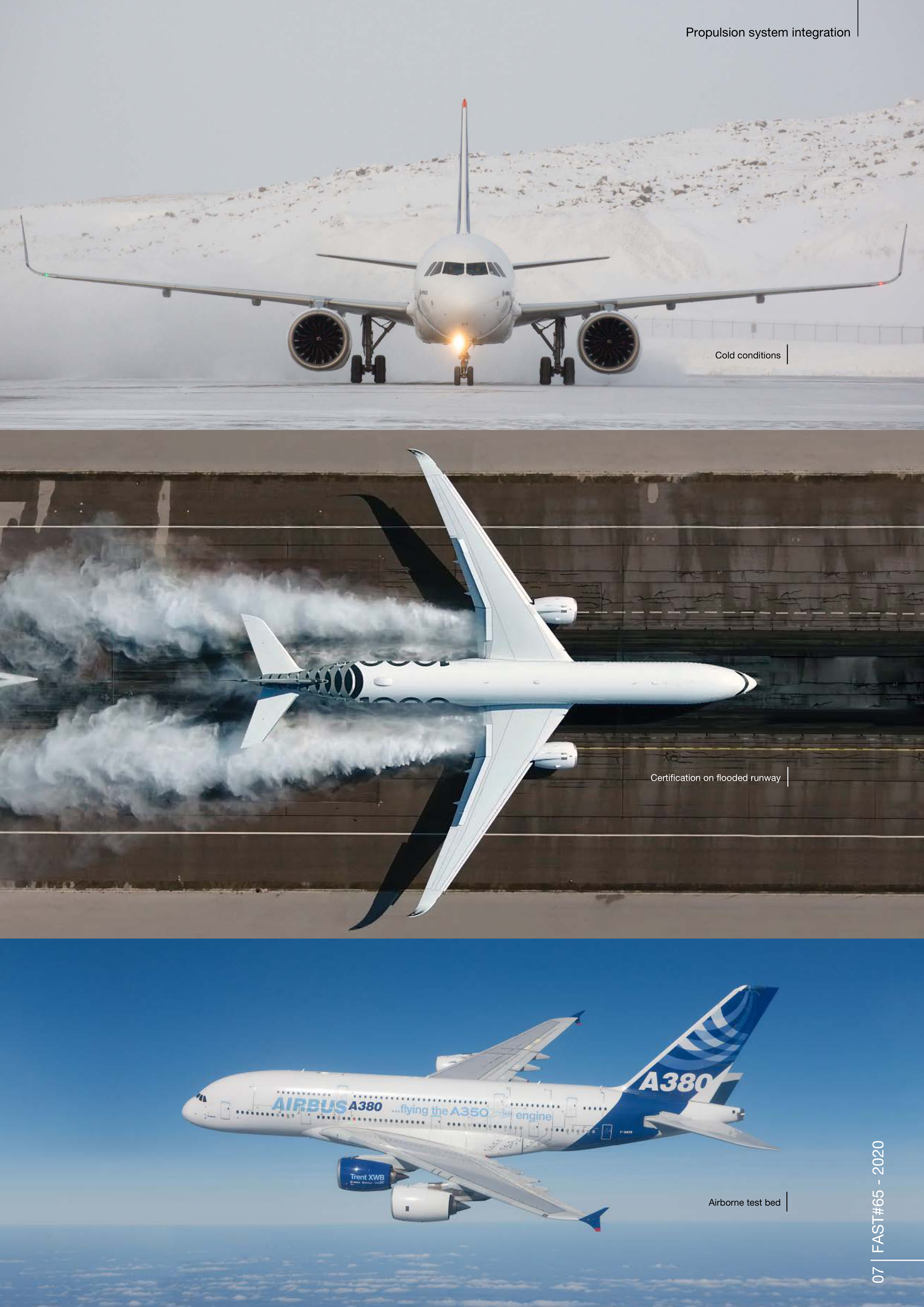
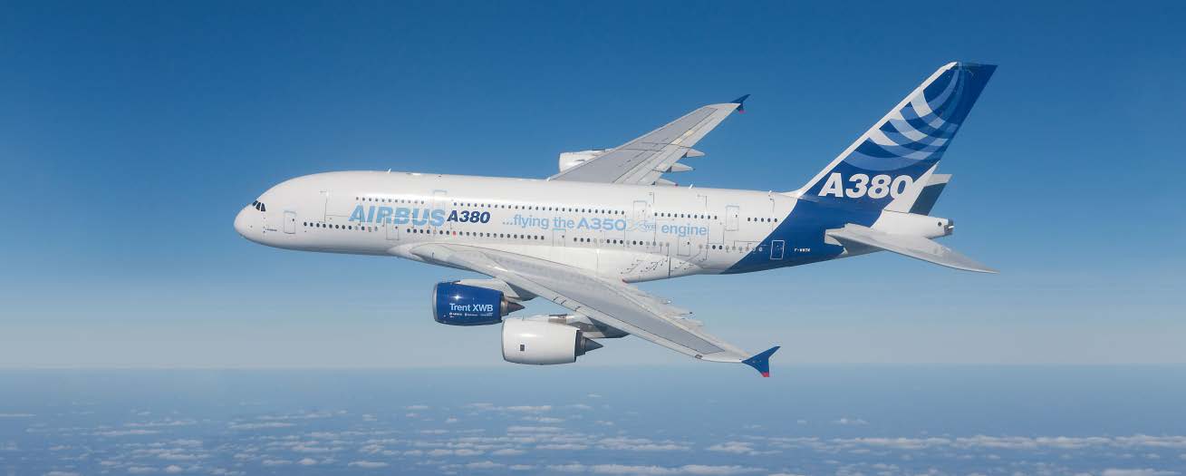
The verification phase starts as soon as the first parts are available. Engine prototypes are tested at the
manufacturer on a ground test bed, as well as at Airbus in both ground and flight testing. A flying test bed
to de-risk the propulsion system may be used ahead of the flight test campaign, especially if the engine
is a new development. This was used on recent programmes such as the A320neo and A350 XWB.
Verification demonstrates that the propulsion system complies with all the applicable specification and
certification requirements. Part of this involves proving it can operate correctly and safely across a range
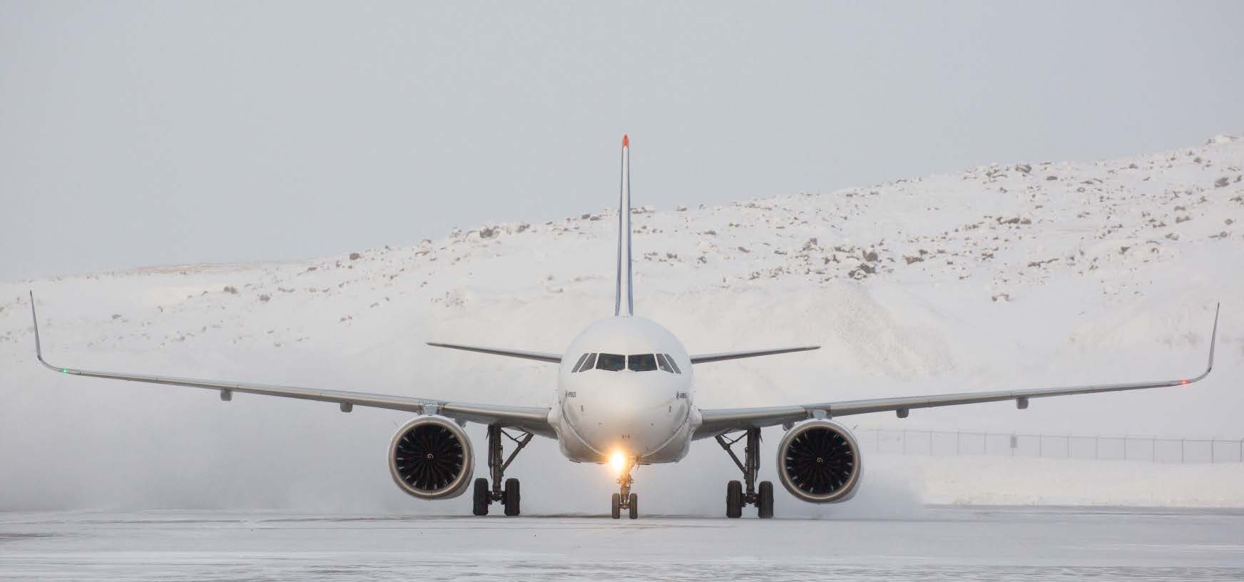
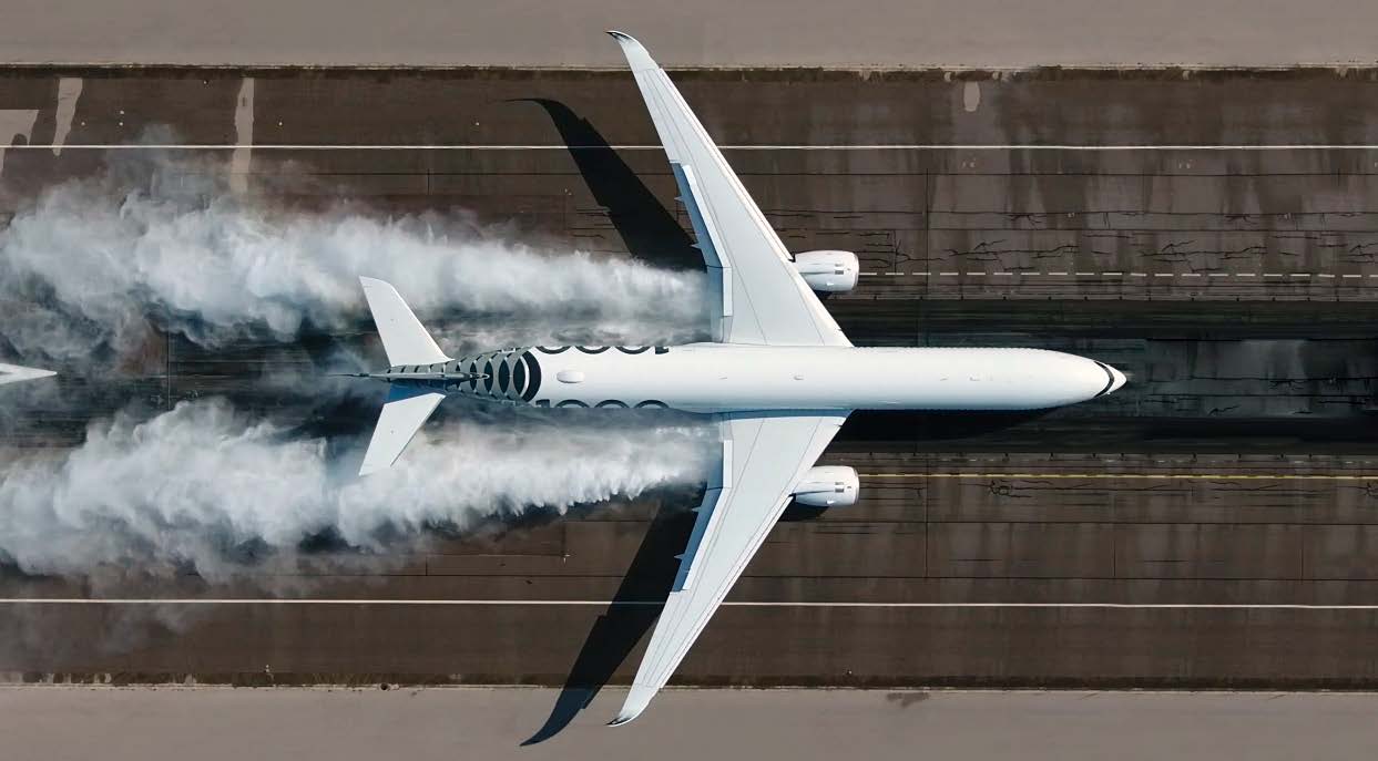
of extreme conditions such as hot and cold weather, ice, high-altitude airports, windy conditions, flooded
runways and lightning strikes. It will also demonstrate that the engine can safely contain a fan blade
release event* and will deliver the required thrust in case of bird or hailstone strike. The robustness to
other failure cases is also demonstrated, like the correct drainage of fluids within the propulsion system.
Engine characteristics are measured throughout the ground and flight test campaigns to ensure fuel
consumption, emissions and noise levels adhere to specified levels. The final phase of engine verification
is intensive endurance testing.
* A fan blade release event is when a blade detaches from the rotating engine fan.
Following verification at both the engine
manufacturer’s and at Airbus, test and
analysis reports are sent to the authorities
to obtain type certification.
First, the engine is certified by the engine
manufacturer complying with the engine
specific regulations (CS-E and FAR Part
33 respectively for EU and US). Then the
propulsion system installation into the
aircraft is certified by Airbus, complying
with aircraft regulations (CS-25 and FAR
Part 25).
Serial manufacturing and assembly are
already underway, with the first serial
engines fitted to the serial nacelles and
delivered to the final assembly line.
After type certification is granted,
customers can take delivery of their
aircraft and begin to operate revenue
flights – the start of an in-service life that
can last 25 years or more.
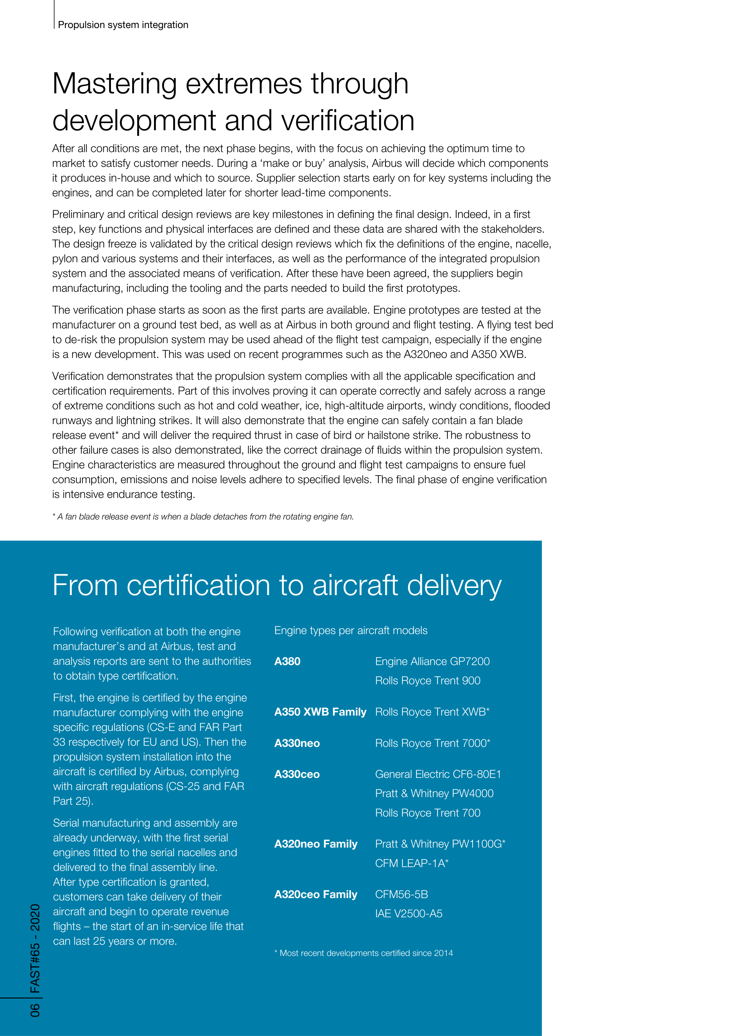
Engine types per aircraft models
A380
Engine Alliance GP7200
Rolls Royce Trent 900
A350 XWB Family
Rolls Royce Trent XWB*
A330neo
Rolls Royce Trent 7000*
A330ceo
General Electric CF6-80E1
Pratt & Whitney PW4000
Rolls Royce Trent 700
A320neo Family
Pratt & Whitney PW1100G*
CFM LEAP-1A*
A320ceo Family
CFM56-5B
IAE V2500-A5
* Most recent developments certified since 2014
Propulsion system integration
From certification to aircraft delivery
07 FAST#65 - 2020
Propulsion system integration
Cold conditions
Certification on flooded runway
Airborne test bed
08 FAST#65 - 2020
Propulsion system integration
How propulsion system integration delivers optimum
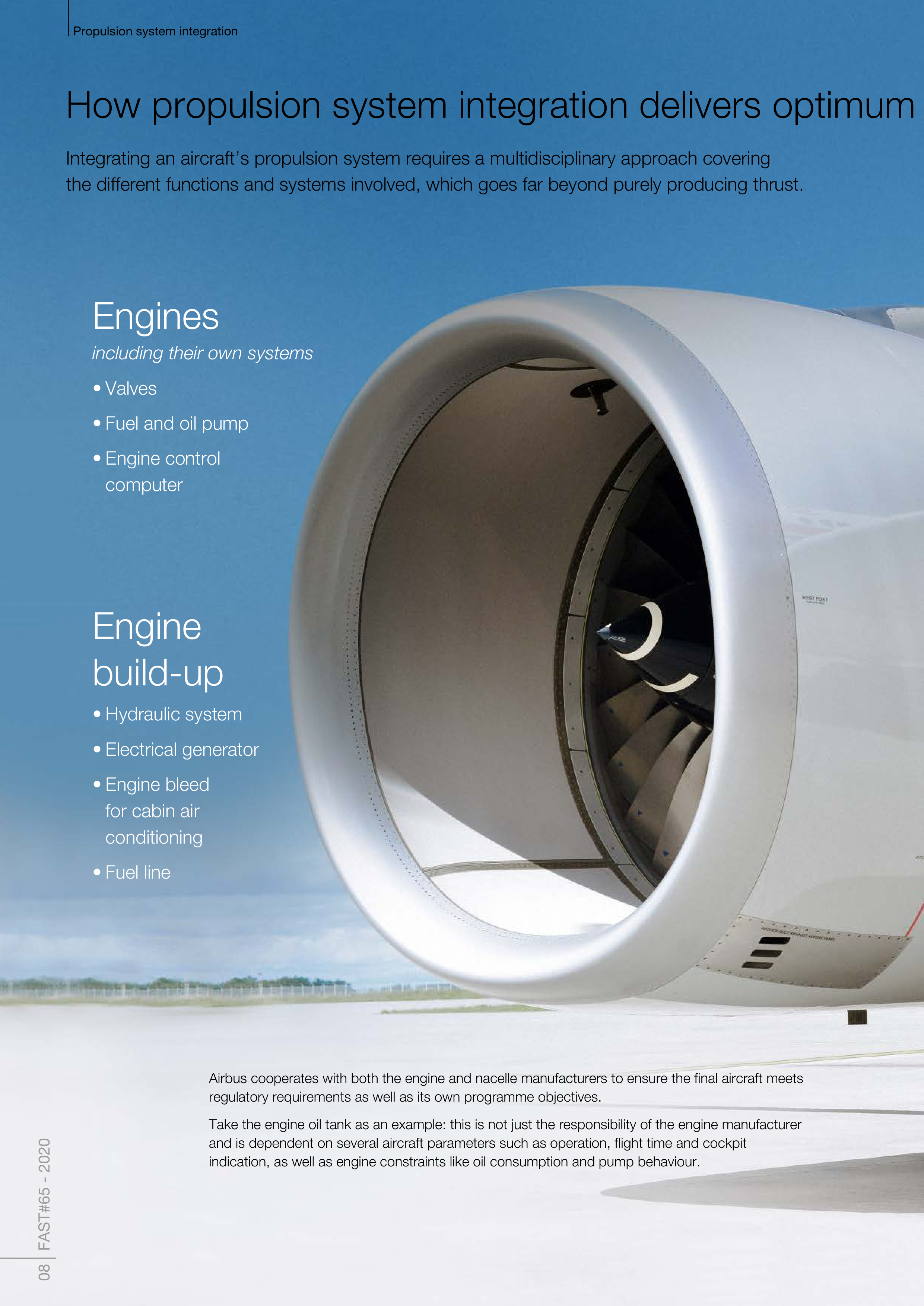
Integrating an aircraft’s propulsion system requires a multidisciplinary approach covering
the different functions and systems involved, which goes far beyond purely producing thrust.
Engines
including their own systems
• Valves
• Fuel and oil pump
• Engine control
computer
Engine
build-up
• Hydraulic system
• Electrical generator
• Engine bleed
for cabin air
conditioning
• Fuel line
Airbus cooperates with both the engine and nacelle manufacturers to ensure the final aircraft meets
regulatory requirements as well as its own programme objectives.
Take the engine oil tank as an example: this is not just the responsibility of the engine manufacturer
and is dependent on several aircraft parameters such as operation, flight time and cockpit
indication, as well as engine constraints like oil consumption and pump behaviour.
Propulsion system integration
09 FAST#65 - 2020
performance
Nacelles
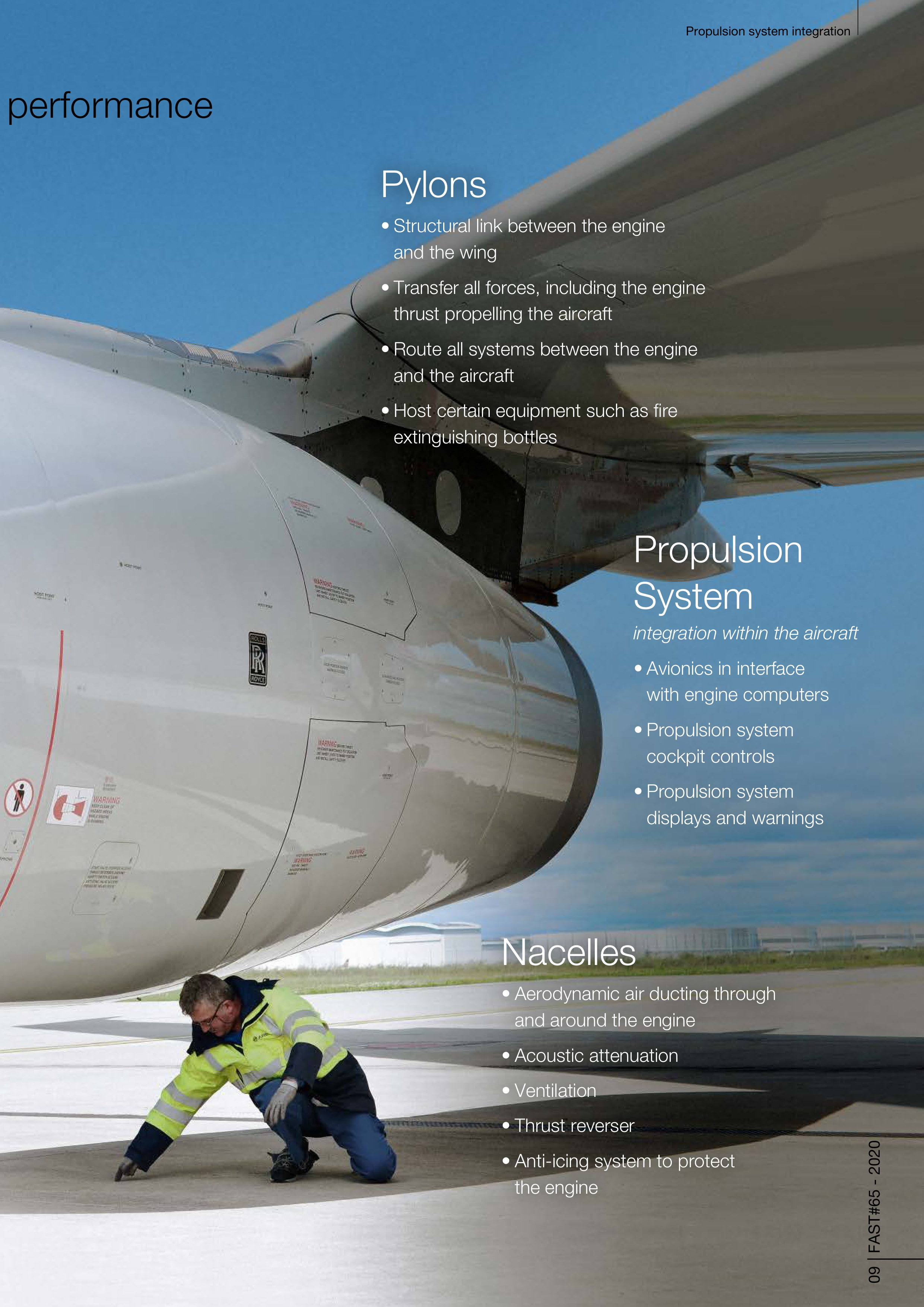
• Aerodynamic air ducting through
and around the engine
• Acoustic attenuation
• Ventilation
• Thrust reverser
• Anti-icing system to protect
the engine
Propulsion
System
integration within the aircraft
• Avionics in interface
with engine computers
• Propulsion system
cockpit controls
• Propulsion system
displays and warnings
Pylons
• Structural link between the engine
and the wing
• Transfer all forces, including the engine
thrust propelling the aircraft
• Route all systems between the engine
and the aircraft
• Host certain equipment such as fire
extinguishing bottles
10 FAST#65 - 2020
Propulsion system integration
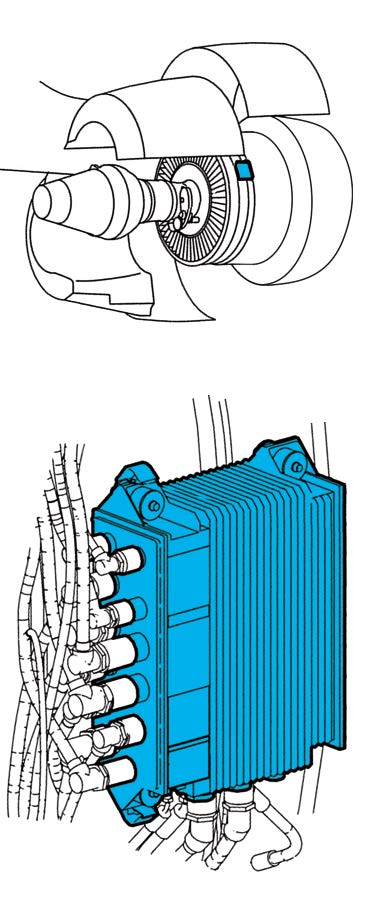
Integrating the engine’s brain
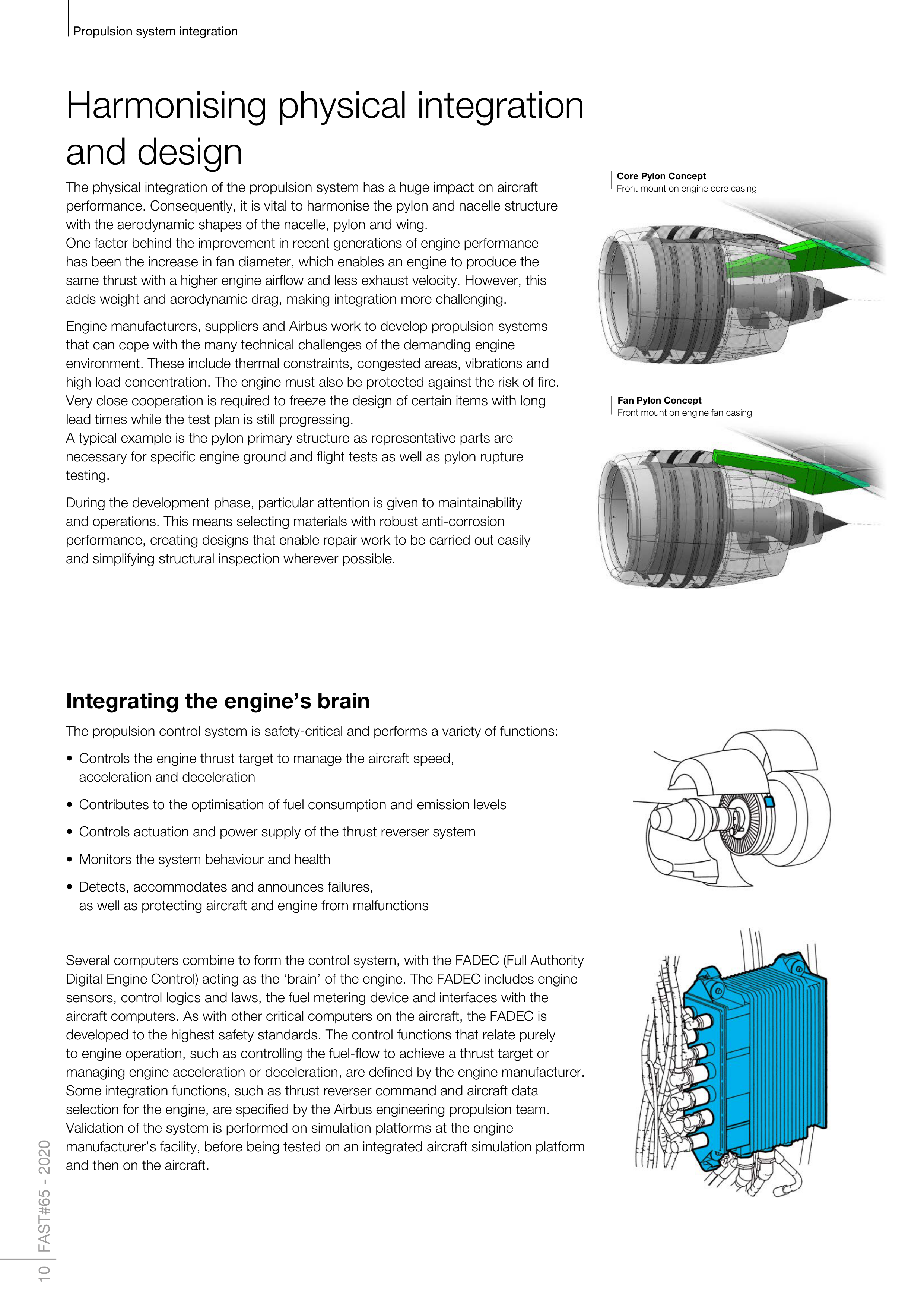
The propulsion control system is safety-critical and performs a variety of functions:
• Controls the engine thrust target to manage the aircraft speed,
acceleration and deceleration
• Contributes to the optimisation of fuel consumption and emission levels
• Controls actuation and power supply of the thrust reverser system
• Monitors the system behaviour and health
• Detects, accommodates and announces failures,
as well as protecting aircraft and engine from malfunctions
Several computers combine to form the control system, with the FADEC (Full Authority
Digital Engine Control) acting as the ‘brain’ of the engine. The FADEC includes engine
sensors, control logics and laws, the fuel metering device and interfaces with the
aircraft computers. As with other critical computers on the aircraft, the FADEC is
developed to the highest safety standards. The control functions that relate purely
to engine operation, such as controlling the fuel-flow to achieve a thrust target or
managing engine acceleration or deceleration, are defined by the engine manufacturer.
Some integration functions, such as thrust reverser command and aircraft data
selection for the engine, are specified by the Airbus engineering propulsion team.
Validation of the system is performed on simulation platforms at the engine
manufacturer’s facility, before being tested on an integrated aircraft simulation platform
and then on the aircraft.
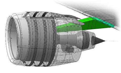
Fan Pylon Concept
Front mount on engine fan casing
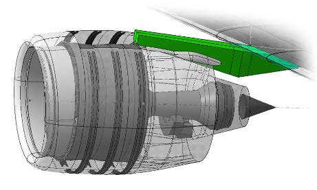
Core Pylon Concept
Front mount on engine core casing
Harmonising physical integration
and design
The physical integration of the propulsion system has a huge impact on aircraft
performance. Consequently, it is vital to harmonise the pylon and nacelle structure
with the aerodynamic shapes of the nacelle, pylon and wing.
One factor behind the improvement in recent generations of engine performance
has been the increase in fan diameter, which enables an engine to produce the
same thrust with a higher engine airflow and less exhaust velocity. However, this
adds weight and aerodynamic drag, making integration more challenging.
Engine manufacturers, suppliers and Airbus work to develop propulsion systems
that can cope with the many technical challenges of the demanding engine
environment. These include thermal constraints, congested areas, vibrations and
high load concentration. The engine must also be protected against the risk of fire.
Very close cooperation is required to freeze the design of certain items with long
lead times while the test plan is still progressing.
A typical example is the pylon primary structure as representative parts are
necessary for specific engine ground and flight tests as well as pylon rupture
testing.
During the development phase, particular attention is given to maintainability
and operations. This means selecting materials with robust anti-corrosion
performance, creating designs that enable repair work to be carried out easily
and simplifying structural inspection wherever possible.
Propulsion system integration
11 FAST#65 - 2020
How to guarantee performance
Airbus specifies a variety of metrics for engine manufacturers to meet, including fuel
consumption, in-flight thrust capability, gaseous emissions and noise – all with the
aim of optimising operational, environmental and economic efficiency for the end
customer. The verification process is executed jointly during the engine development
and test phase.
Engine performance follow-up during development is key to anticipate entry-into-
service product performance. This is achieved through a joint analysis of the engine
manufacturer’s ground tests and final flight tests conducted by Airbus. FADEC thrust
tables are developed jointly to deliver optimal aircraft performance in different
conditions. A hot environment like the Middle East, for example, can require specific
thrust capabilities.
Ensuring system maturity
Reaching optimum aircraft maturity at entry-into-service is essential for all partners.
The propulsion system is a major part of regular maintenance procedures. Together
with the company’s suppliers, Airbus considers the maturity of the propulsion system
at every stage of its life cycle. The shared objective is to prevent issues of immaturity
affecting a fleet, as well as ensuring fleet management plans are available for known
issues and constantly striving for improvements that will enhance reliability.
During pre-development, the maturity of new key technologies is assessed and
extensive feedback analyses are conducted to influence design or architecture
choices like electrical or hydraulic thrust reversers. Between the preliminary and
critical design reviews, much more exhaustive analyses are carried out to assess new
equipment suppliers, the robustness of all new technologies and to apply technical
lessons learned from previous aircraft programmes. Airbus works with suppliers to
ensure an adequate validation and verification strategy on any new components.
Rigorous process for safety and certification
Propulsion is one of the most critical functions of an aircraft. Engine manufacturers are
therefore major contributors to aircraft safety, and they must first certify their engine
to obtain a dedicated Engine Type Certificate to meet the safety regulations of CS-E
and FAR33.
Once certified, the engines are integrated on the aircraft to form a propulsion system
that will also have to comply with dedicated integration certification requirements
under the regulations of CS25 and FAR25. This ensures all engines operate as
expected when fully integrated with the aircraft structure, systems and avionics
throughout the flight envelope, and that relevant safety requirements are met.
It is achieved through a systematic and comprehensive assessment of the propulsion
system architecture, design and installation. The assessment covers all potential
failures of engines like the loss of thrust, internal fires or uncontained failures that
release high-energy debris. It ensures that aircraft integration incorporates sufficient
safety margins to sustain these engine failures.
The work does not stop there, however. The propulsion system is tracked throughout
an aircraft’s life to ensure it remains airworthy and within dedicated safety margins
when failures occur. Mitigations are defined and implemented whenever necessary.
Both Airbus and the engine manufacturer must follow their own but complementary
continued airworthiness obligations to ensure aircraft safety throughout its life.
Over the last two decades, the worldwide rate of engine in-flight shut-down has been
divided by 10 (*), showing a continuous joint effort from engine manufacturers
and Airbus to improve propulsion system safety.
(*) source CAAM international working group
12 FAST#65 - 2020
Propulsion system integration
Jet
Combustion
Turbine
Fan forward
Fan rearward
Bleed Valve
Total airframe
38%
32%
19%
29%
14%
27%
34%
25%
49%
7%
3%
2%
2%
1%
1%
17%
Flyover
Approach
Lateral
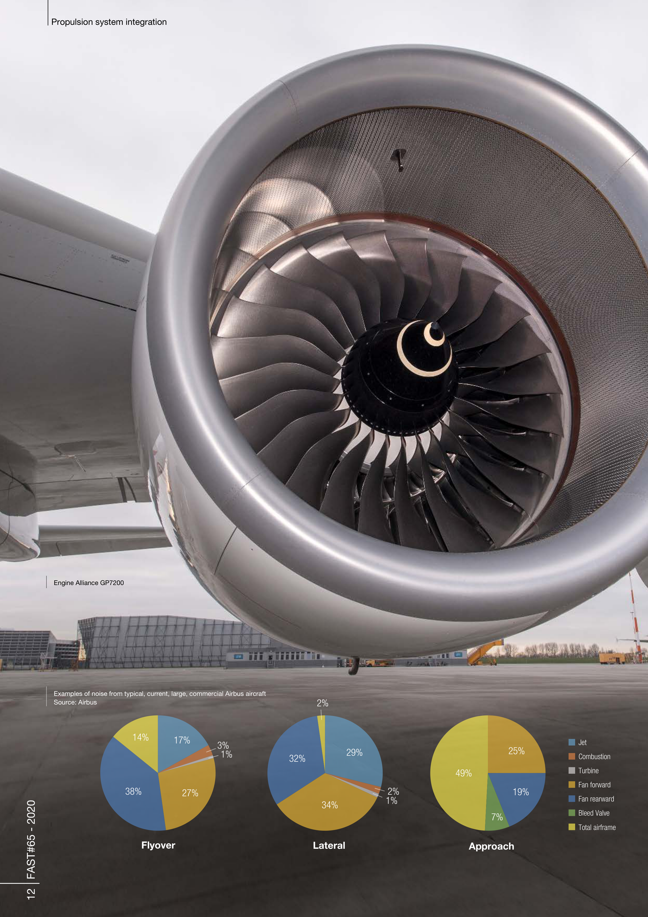
Engine Alliance GP7200
Examples of noise from typical, current, large, commercial Airbus aircraft
Source: Airbus
Propulsion system integration
13 FAST#65 - 2020
Minimising noise
Propulsion systems are the major contributor to community noise emissions on modern commercial aircraft at
take-off. They also generate about half of the noise emission during the final approach phase, in addition to airframe
aerodynamic noise sources like landing gears and wing flaps and slats. They contribute significantly to cabin noise,
too, particularly during initial climb in the front cabin and most of the cruise in the rear cabin.
The way engines are installed and integrated play an important role in the acoustic performance and quality of an
aircraft. Most of the nacelles’ inner walls are covered with acoustic absorbing treatment to provide acoustic attenuation
to engine noise. The treatments are carefully optimized to match the characteristics of the main turbomachinery noise
sources and prevent 50-70% of acoustic energy generated by the engine from being radiated outside. The result is
a reduction of between three and five EPNdB (Equivalent Perceived Noise in Decibels) at each control point.
Airbus has developed numerous innovative technologies to minimise noise emissions. One example is the zero-splice
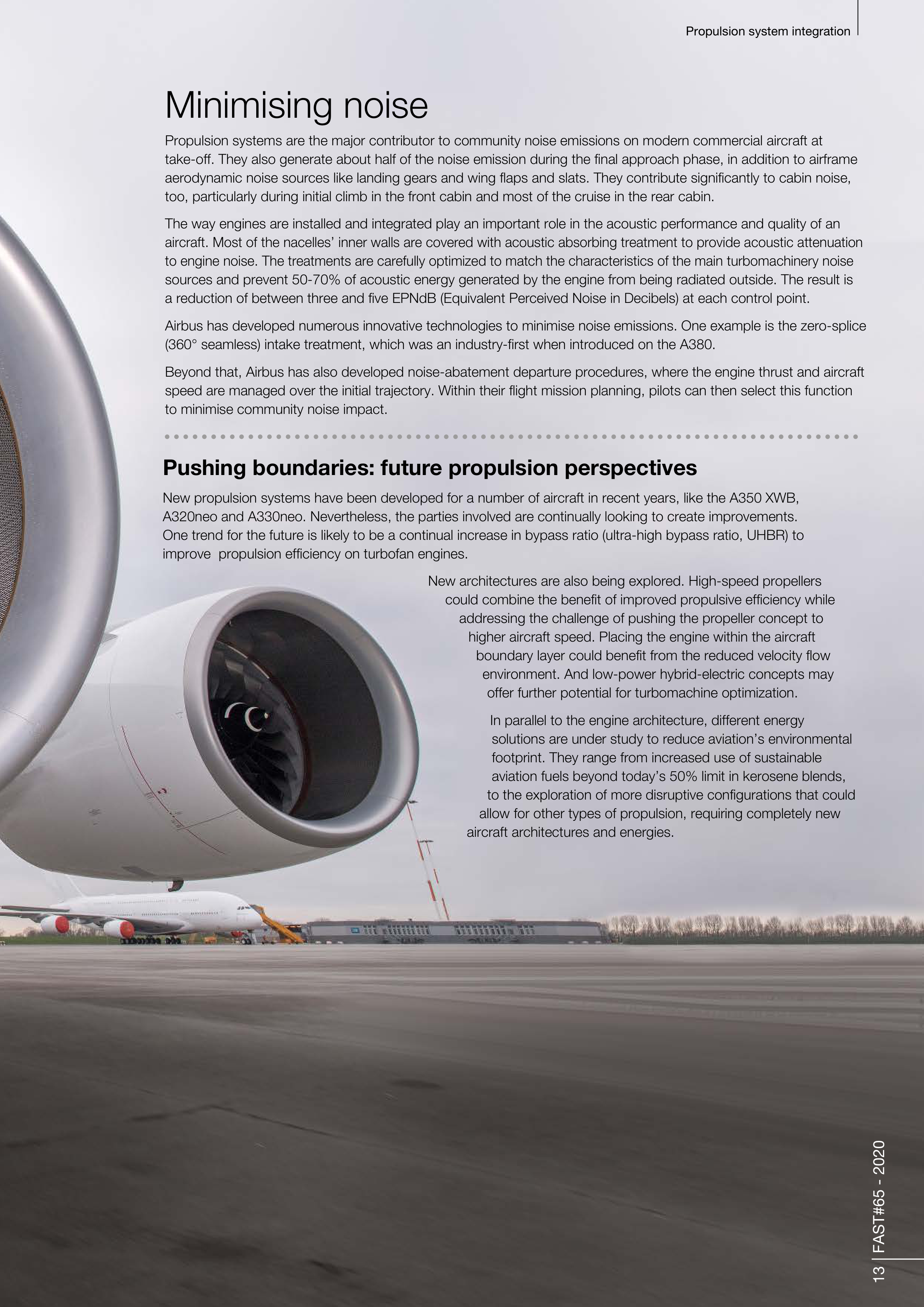
(360° seamless) intake treatment, which was an industry-first when introduced on the A380.
Beyond that, Airbus has also developed noise-abatement departure procedures, where the engine thrust and aircraft
speed are managed over the initial trajectory. Within their flight mission planning, pilots can then select this function
to minimise community noise impact.
Pushing boundaries: future propulsion perspectives
New propulsion systems have been developed for a number of aircraft in recent years, like the A350 XWB,
A320neo and A330neo. Nevertheless, the parties involved are continually looking to create improvements.
One trend for the future is likely to be a continual increase in bypass ratio (ultra-high bypass ratio, UHBR) to
improve propulsion efficiency on turbofan engines.
New architectures are also being explored. High-speed propellers
could combine the benefit of improved propulsive efficiency while
addressing the challenge of pushing the propeller concept to
higher aircraft speed. Placing the engine within the aircraft
boundary layer could benefit from the reduced velocity flow
environment. And low-power hybrid-electric concepts may
offer further potential for turbomachine optimization.
In parallel to the engine architecture, different energy
solutions are under study to reduce aviation’s environmental
footprint. They range from increased use of sustainable
aviation fuels beyond today’s 50% limit in kerosene blends,
to the exploration of more disruptive configurations that could
allow for other types of propulsion, requiring completely new
aircraft architectures and energies.

14 FAST#65 - 2020
The defining moment
Making it easier to choose cabin options
Choosing the right options for a new aircraft cabin can be daunting for airline customers.
Airbus aircraft cabins have become far more customisable in recent years,
leaving customers facing a huge number of choices, but technological innovations
are helping to smooth the process.
Thierry ORILLAC,
A350 XWB Cabin Project Leader
explains more:
People who haven’t worked in an airline cabin, don’t always realise how complex it is.
They can just think it’s about seats, toilets and a galley and that’s it.
But there are also partitions, curtains, storage, lights, air conditioning, cabin communication systems
and much more. And there is also a lot of interconnection in the cabin – so there is a domino effect,
if you change one option it has knock-on effects elsewhere.
Driving an airline’s choices in the cabin are the different objectives of its teams – so cabin definition means
balancing the priorities of management, alongside marketing teams and other airline teams such as cabin
crew, catering and engineering.
Each cabin definition project is unique and as detailed as the airline wishes. Airlines’ aims vary depending
on their goal as a carrier – for example, whether they’re targeting domestic or international passengers.
But they all want to differentiate themselves from the competition. And they are all seeking profitability.
If they are investing a lot in the cabin, they also want a quick return on that investment.
Article by
Thierry ORILLAC
A350 Cabin Project Leader
AIRBUS
thierry.orillac@airbus.com
Alexander JUERS
Project manager, Customer Definition Centre
AIRBUS
alexander.juers@airbus.com
15 FAST#65 - 2020
The defining moment
Cabin criteria
There are several variables for airline customers
to consider when defining their cabin.
If it’s a big airline, there can be many stakeholders. While with
smaller airlines, we are sometimes in direct contact with the
CEO or board members. We have many ways to support the
customer and we work to balance the best package for them
and help them to take a decision.
Alongside the customer’s requirements, there are also
regulatory obligations from the aviation authorities and technical
constraints from Airbus – for example, not exceeding weight
limits. In addition, there can be mandatory operational
requirements from the airline to be considered – for example,
having a minimum number of trolleys by the aircraft door, or no
seats in front of the lavatory entrance.
After that, airlines are looking at points of differentiation for their
cabin, features they want for passengers, requirements for
cabin crew to perform effectively, and any additional necessities
for pilots or engineering and maintenance personnel.
The requirements of airline and Airbus suppliers also need
considering. We work in partnership with them to get the
required equipment into the cabin.
The layout of the cabin is the main factor as it provides the basis
for the cabin definition. This depends on the needs of the
airlines, but we also have to consider integration into the
aircraft. We’re creating a unique solution for each airline based
on its requirement – considering seat models, lavatories,
storage etc.
The cabin layout is modified and updated as the project
progresses. Usually it’s about finding a compromise that works
for the airlines, for example, there is a maximum number of
possible seats and galleys. It’s about adapting the original
requirement.
Definition journey
The Airbus teams help guide the customer through the definition process.
After the kick-off meeting, customers have a product offer demonstration
at
the CDC, where they see the variety of the cabin offer. Suppliers – such as seat
manufacturers - are present as needed to explain their products.
After the demonstration, comes the definition meeting. And then at the end is the
Cabin Definition Closure Meeting, where we go step-by-step through the definition
document. Then we sign the definition document with the customer and suppliers.
Based on that document we build the cabin. Once that is done, the delivery centre
and other customer teams take care of the delivery phase.


The defining moment
16 FAST#65 - 2020
Customers can see what their
future products will look like
– using fully-integrated cabin
mock-ups, virtual reality
and mixed-reality tools,
all under one roof
One-stop shop
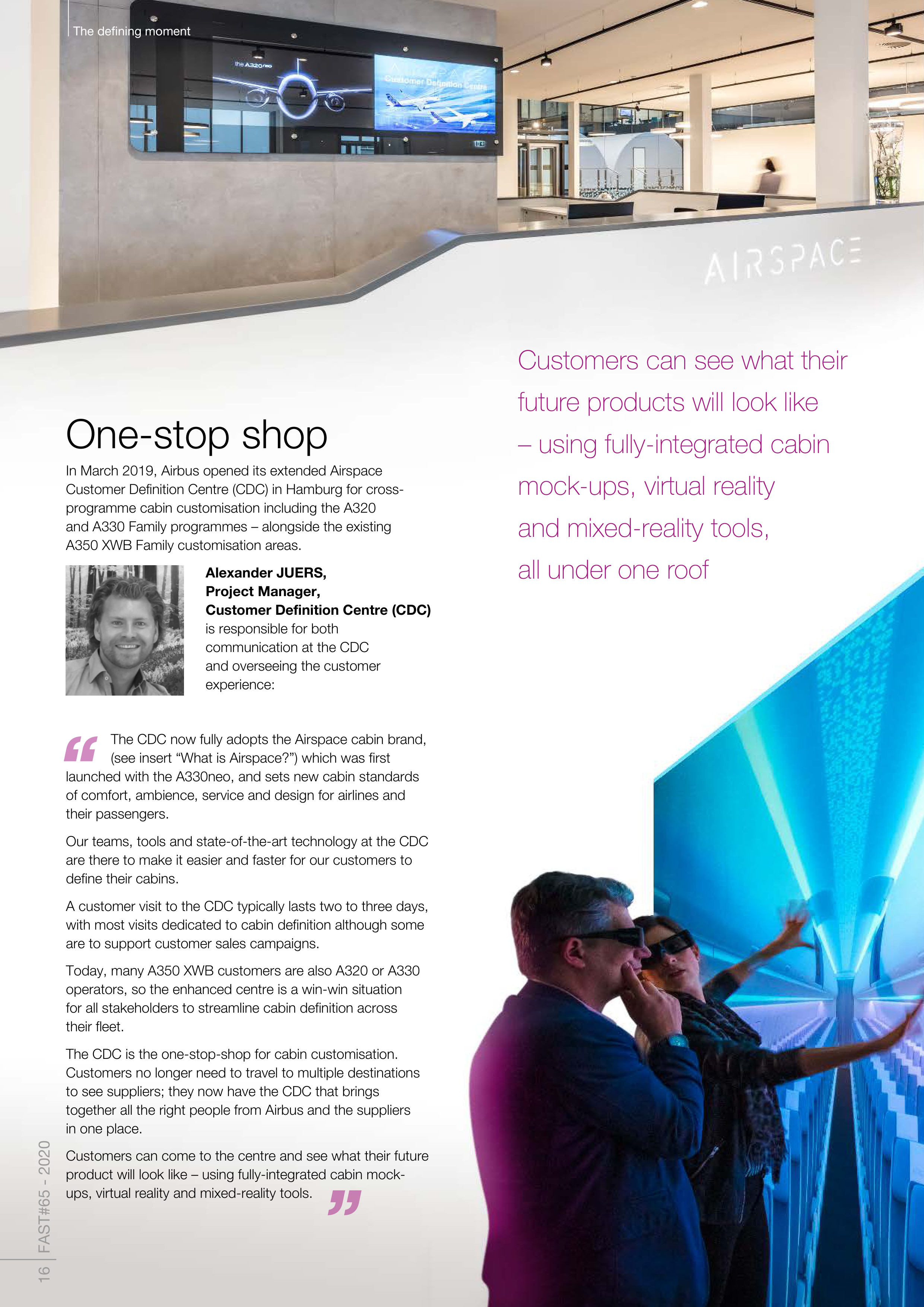
In March 2019, Airbus opened its extended Airspace
Customer Definition Centre (CDC) in Hamburg for cross-
programme cabin customisation including the A320
and A330 Family programmes – alongside the existing
A350 XWB Family customisation areas.
Alexander JUERS,
Project Manager,
Customer Definition Centre (CDC)
is responsible for both
communication at the CDC
and overseeing the customer
experience:
The CDC now fully adopts the Airspace cabin brand,
(see insert “What is Airspace?”) which was first
launched with the A330neo, and sets new cabin standards
of comfort, ambience, service and design for airlines and
their passengers.
Our teams, tools and state-of-the-art technology at the CDC
are there to make it easier and faster for our customers to
define their cabins.
A customer visit to the CDC typically lasts two to three days,
with most visits dedicated to cabin definition although some
are to support customer sales campaigns.
Today, many A350 XWB customers are also A320 or A330
operators, so the enhanced centre is a win-win situation
for all stakeholders to streamline cabin definition across
their fleet.
The CDC is the one-stop-shop for cabin customisation.
Customers no longer need to travel to multiple destinations
to see suppliers; they now have the CDC that brings
together all the right people from Airbus and the suppliers
in one place.
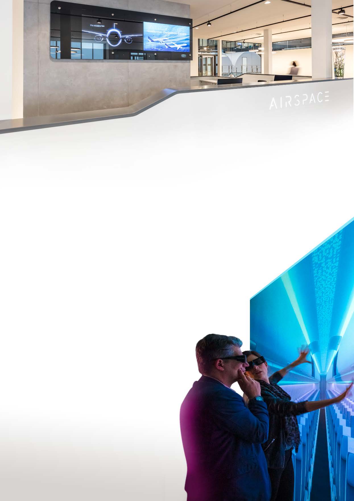
Customers can come to the centre and see what their future
product will look like – using fully-integrated cabin mock-
ups, virtual reality and mixed-reality tools.



The defining moment
What is Airspace?
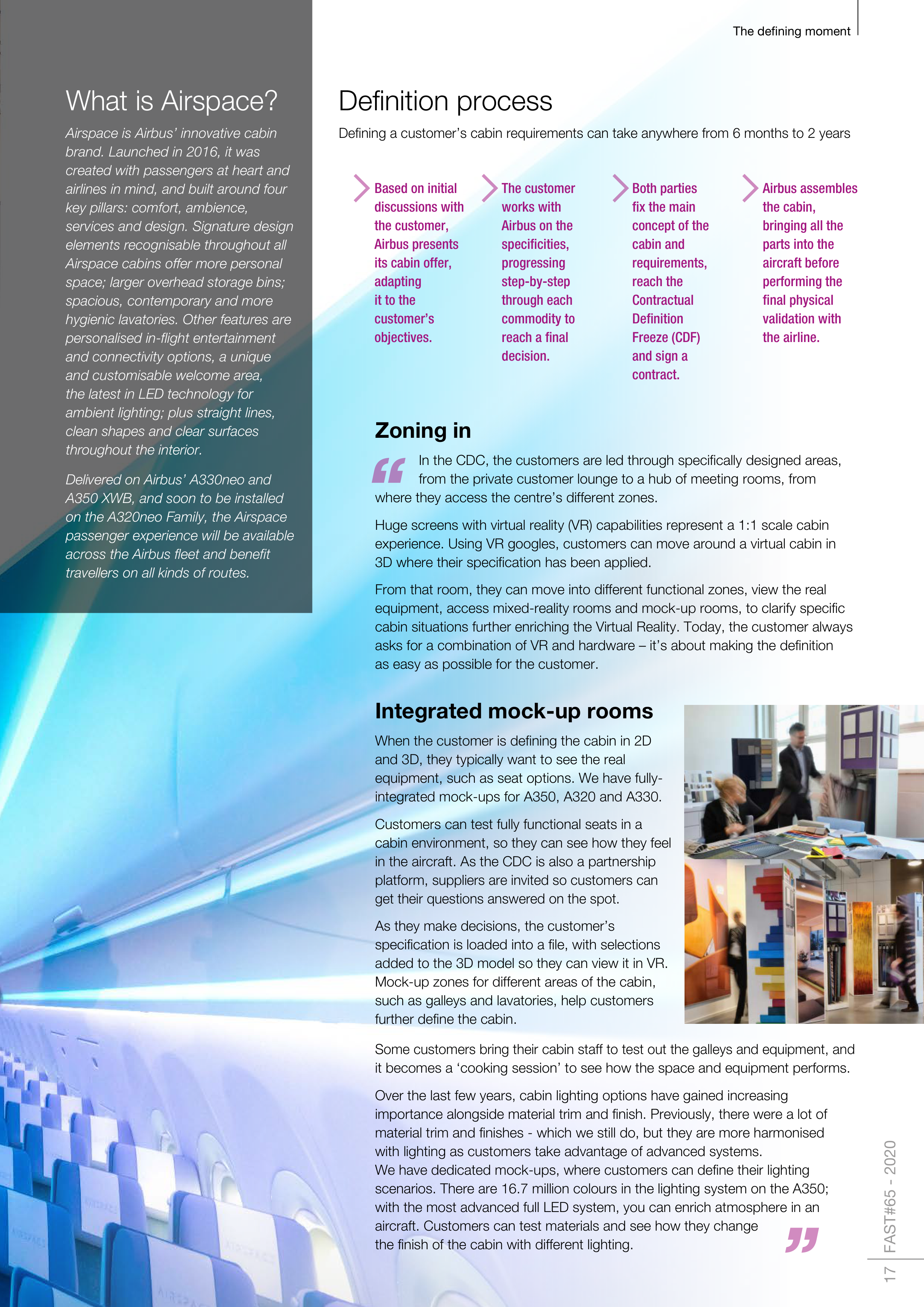
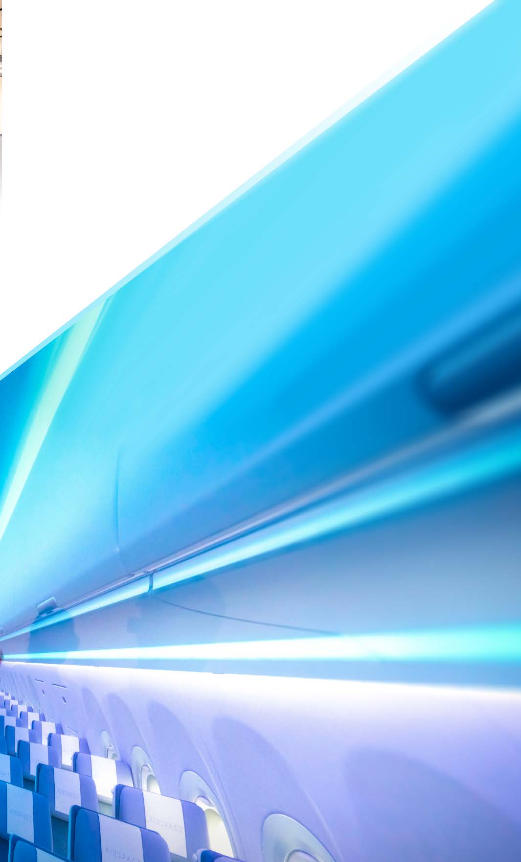
Airspace is Airbus’ innovative cabin
brand. Launched in 2016, it was
created with passengers at heart and
airlines in mind, and built around four
key pillars: comfort, ambience,
services and design. Signature design
elements recognisable throughout all
Airspace cabins offer more personal
space; larger overhead storage bins;
spacious, contemporary and more
hygienic lavatories. Other features are
personalised in-flight entertainment
and connectivity options, a unique
and customisable welcome area,
the
latest in LED technology for
ambient lighting; plus straight lines,
clean shapes and clear surfaces
throughout the interior.
Delivered on Airbus’ A330neo and
A350 XWB, and soon to be installed
on the A320neo Family, the Airspace
passenger experience will be available
across the Airbus fleet and benefit
travellers on all kinds of routes.
17 FAST#65 - 2020
Zoning in
In the CDC, the customers are led through specifically designed areas,
from the private customer lounge to a hub of meeting rooms, from
where they access the centre’s different zones.
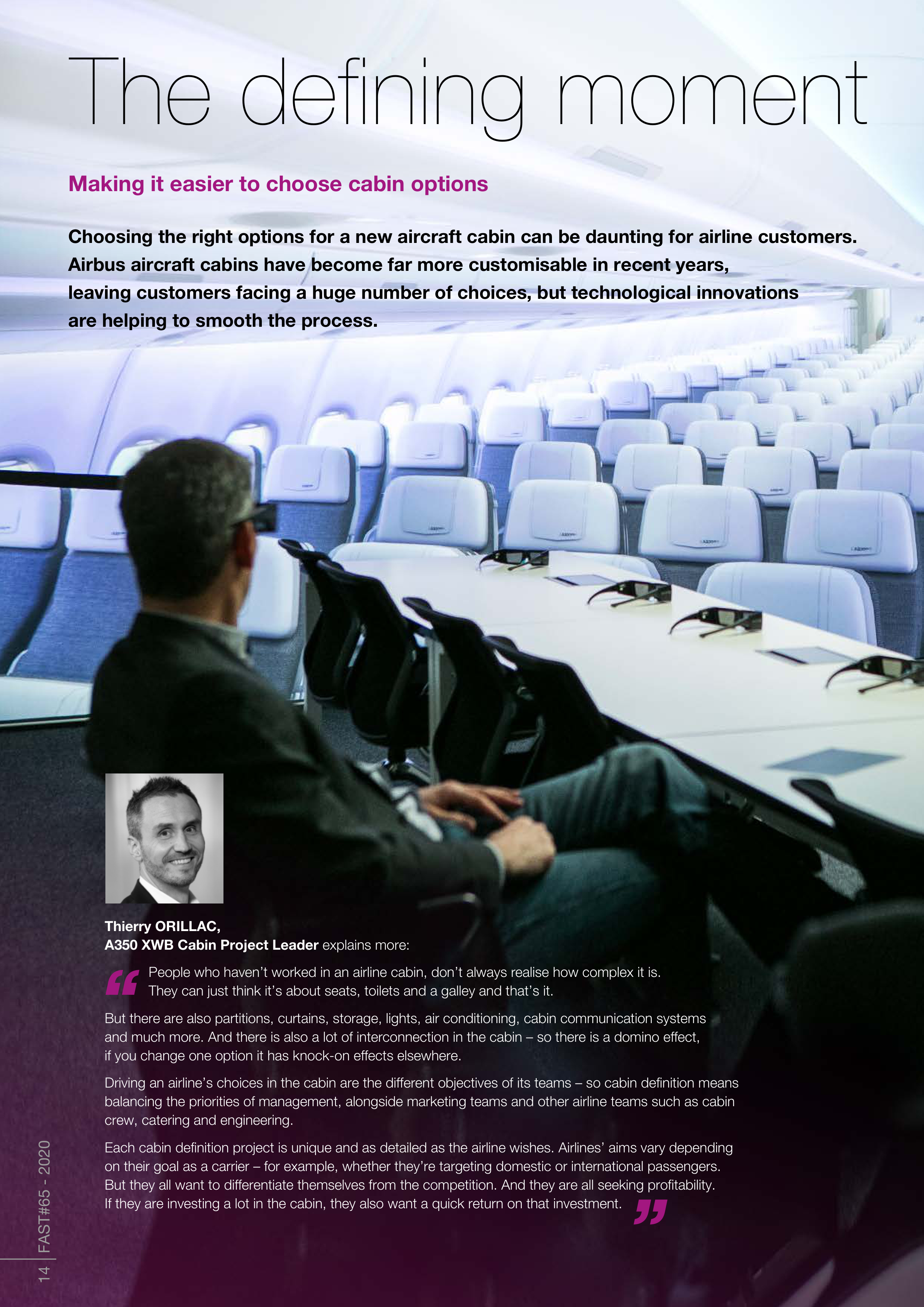
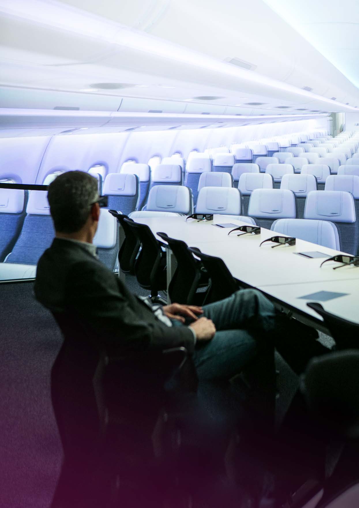
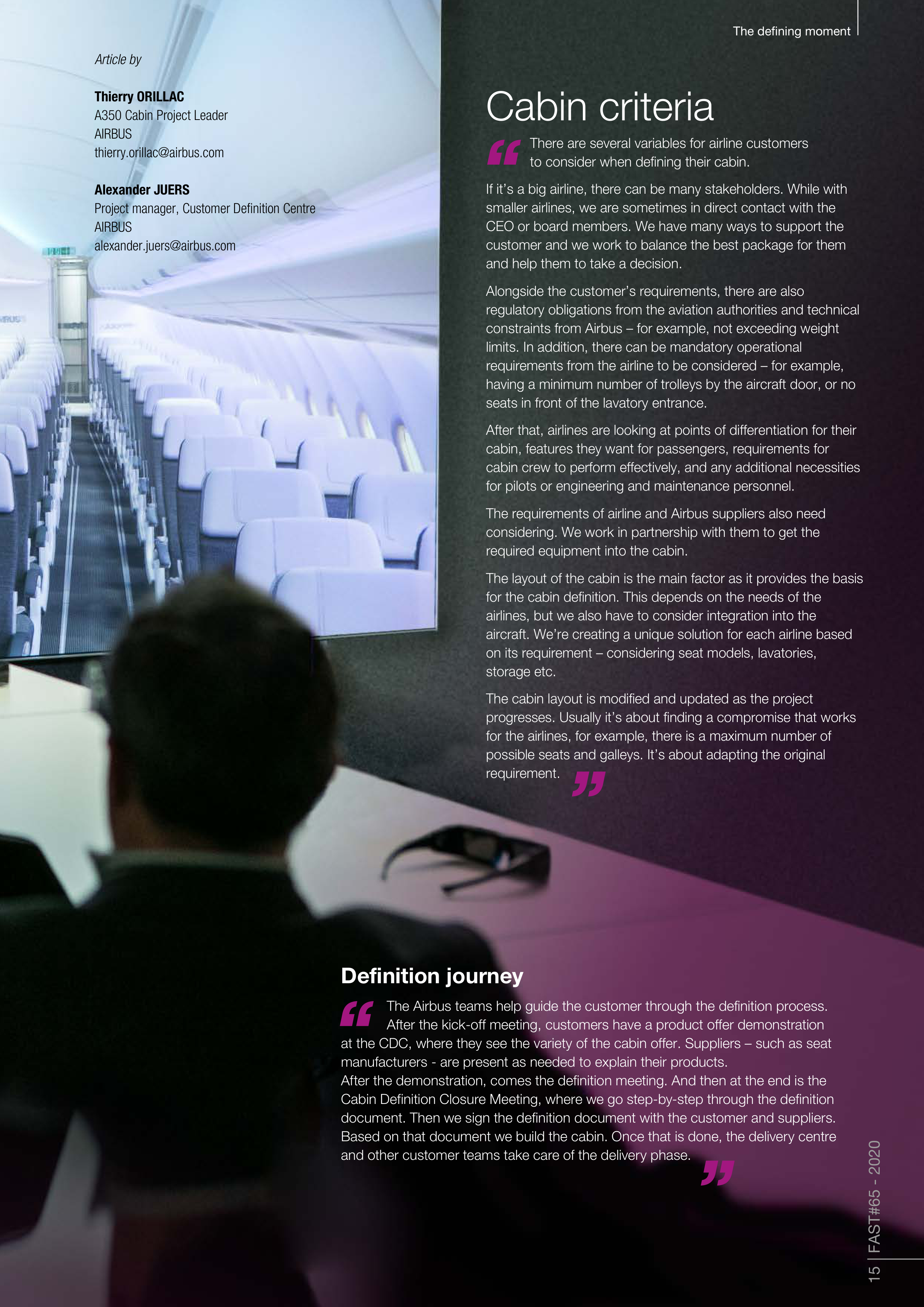
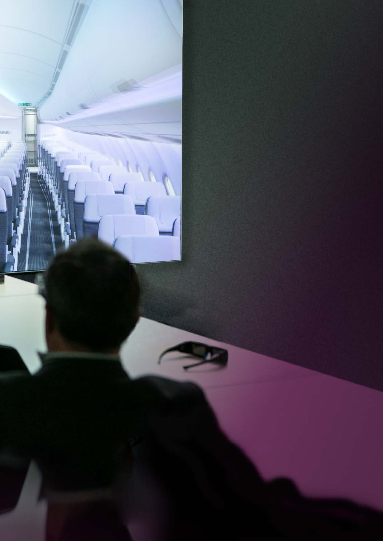
Huge screens with virtual reality (VR) capabilities represent a 1:1 scale cabin
experience. Using VR googles, customers can move around a virtual cabin in
3D where their specification has been applied.
From that room, they can move into different functional zones, view the real
equipment, access mixed-reality rooms and mock-up rooms, to clarify specific
cabin situations further enriching the Virtual Reality. Today, the customer always
asks for a combination of VR and hardware – it’s about making the definition
as easy as possible for the customer.
Integrated mock-up rooms
When the customer is defining the cabin in 2D
and 3D, they typically want to see the real
equipment, such as seat options. We have fully-
integrated mock-ups for A350, A320 and A330.
Customers can test fully functional seats in a
cabin environment, so they can see how they feel
in the aircraft. As the CDC is also a partnership
platform,
suppliers are invited so customers can
get their questions answered on the spot.
As they make decisions, the customer’s
specification is loaded into a file, with selections
added to the 3D model so they can view it in VR.
Mock-up zones for different areas of the cabin,
such as galleys and lavatories, help customers
further define the cabin.
Some customers bring their cabin staff to test out the galleys and equipment, and
it becomes a ‘cooking session’ to see how the space and equipment performs.
Over the last few years, cabin lighting options have gained increasing
importance alongside material trim and finish. Previously, there were a lot of
material trim and finishes - which we still do, but they are more harmonised
with lighting as customers take advantage of advanced systems.
We have dedicated mock-ups, where customers can define their lighting
scenarios. There are 16.7 million colours in the lighting system on the A350;
with the most advanced full LED system, you can enrich atmosphere in an
aircraft. Customers can test materials and see how they change
the finish of the cabin with different lighting.
Definition process
Defining a customer’s cabin requirements can take anywhere from 6 months to 2 years
Based on initial
discussions with
the customer,
Airbus presents
its cabin offer,
adapting
it to the
customer’s
objectives.
The customer
works with
Airbus on the
specificities,
progressing
step-by-step
through each
commodity to
reach a final
decision.
Both parties
fix the main
concept of the
cabin and
requirements,
reach the
Contractual
Definition
Freeze (CDF)
and sign a
contract.
Airbus assembles
the cabin,
bringing all the
parts into the
aircraft before
performing the
final physical
validation with
the airline.
18 FAST#65 - 2020
The defining moment
Configuring the layout
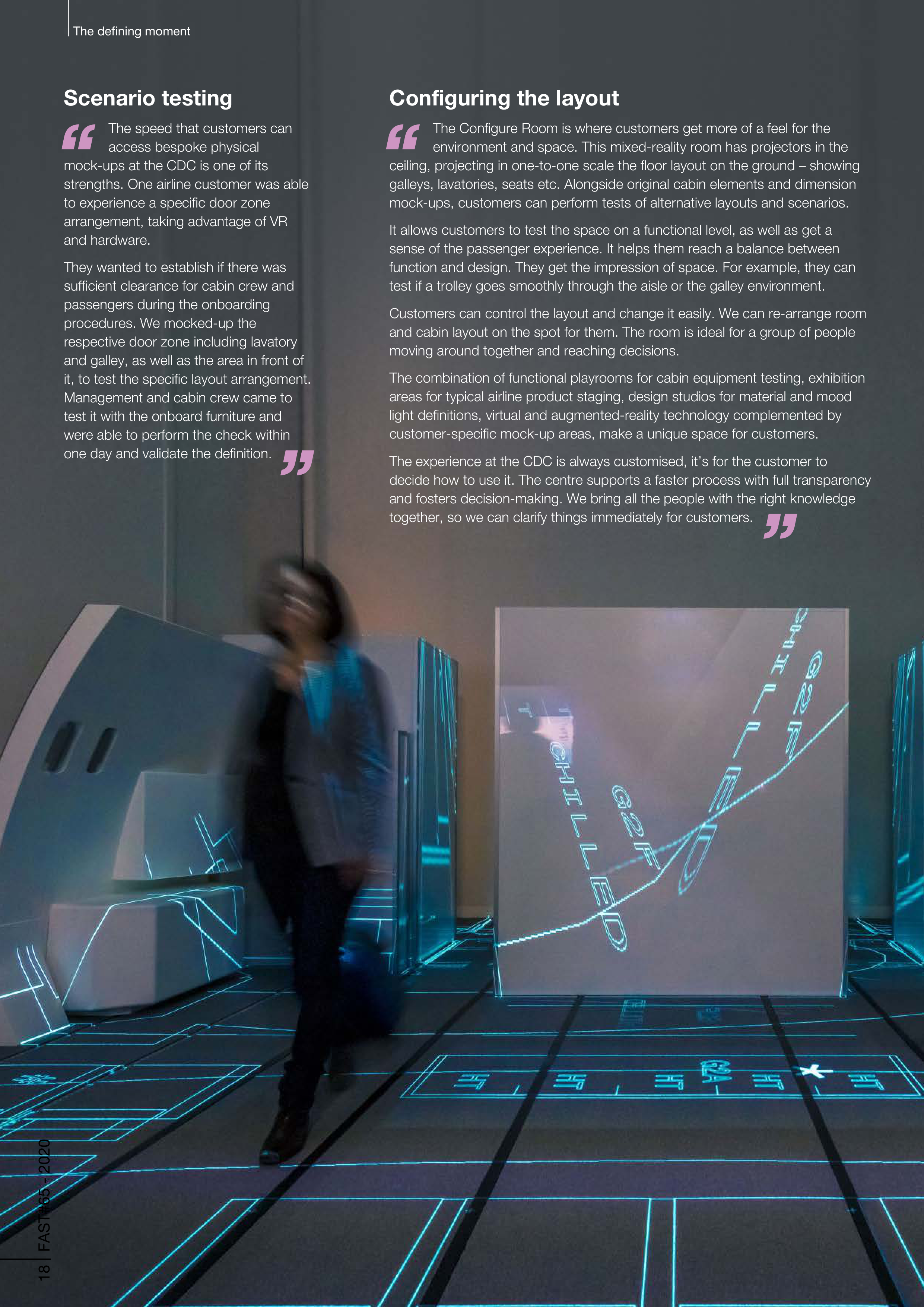
The Configure Room is where customers get more of a feel for the
environment and space. This mixed-reality room has projectors in the
ceiling, projecting in one-to-one scale the floor layout on the ground – showing
galleys, lavatories, seats etc. Alongside original cabin elements and dimension
mock-ups, customers can perform tests of alternative layouts and scenarios.
It allows customers to test the space on a functional level, as well as get a
sense of the passenger experience. It helps them reach a balance between
function and design. They get the impression of space. For example, they can
test if a trolley goes smoothly through the aisle or the galley environment.
Customers can control the layout and change it easily. We can re-arrange room
and cabin layout on the spot for them. The room is ideal for a group of people
moving around together and reaching decisions.
The combination of functional playrooms for cabin equipment testing, exhibition
areas for typical airline product staging, design studios for material and mood
light definitions, virtual and augmented-reality technology complemented by
customer-specific mock-up areas, make a unique space for customers.
The experience at the CDC is always customised, it’s for the customer to
decide how to use it. The centre supports a faster process with full transparency
and fosters decision-making. We bring all the people with the right knowledge
together, so we can clarify things immediately for customers.
Scenario testing
The speed that customers can
access bespoke physical
mock-ups at the CDC is one of its
strengths. One airline customer was able
to experience a specific door zone
arrangement, taking advantage of VR
and hardware.
They wanted to establish if there was
sufficient clearance for cabin crew and
passengers during the onboarding
procedures. We mocked-up the
respective door zone including lavatory
and galley, as well as the area in front of
it, to test the specific layout arrangement.
Management and cabin crew came to
test it with the onboard furniture and
were able to perform the check within
one day and validate the definition.



The defining moment
Retro-fitting
Retro-fitting a cabin has more
technical constraints than
line-fitting. We have to take into
account the current aircraft we’re
going to refurbish and the current
specification it has, so there can
be additional limitations.
Most of the airlines want to minimise
the cost of refurbishment, so they
want to use the most cost-efficient
modifications – and we can support
them to do that.
Customer experience
Morio Suzuki
Manager, Interior Group, Engineering Project Office,
JAL Engineering (JALEC)
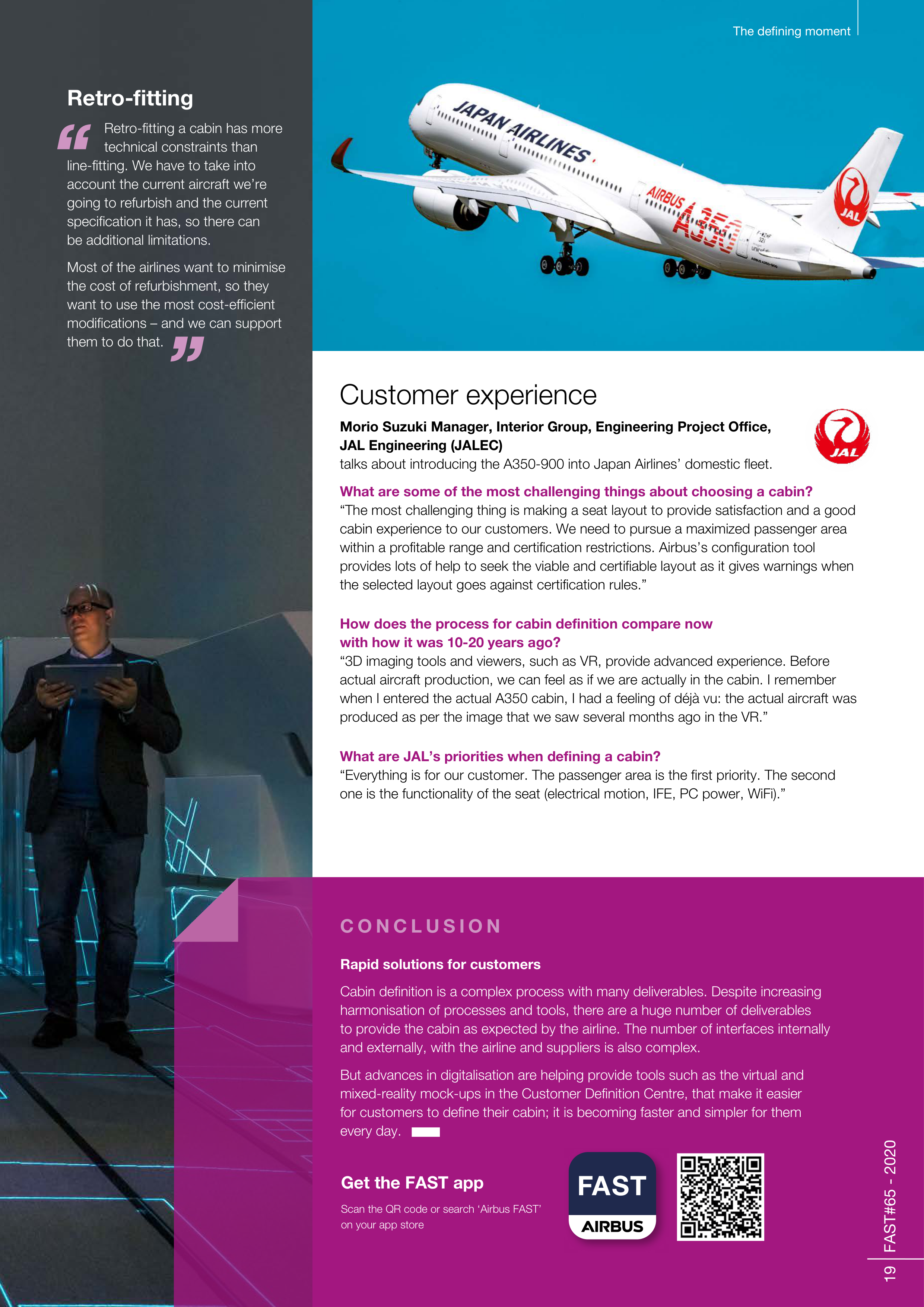
talks about introducing the A350-900 into Japan Airlines’ domestic fleet.
What are some of the most challenging things about choosing a cabin?
“The most challenging thing is making a seat layout to provide satisfaction and a good
cabin experience to our customers. We need to pursue a maximized passenger area
within a profitable range and certification restrictions. Airbus’s configuration tool
provides lots of help to seek the viable and certifiable layout as it gives warnings when
the selected layout goes against certification rules.”
How does the process for cabin definition compare now
with how it was 10-20 years ago?
“3D imaging tools and viewers, such as VR, provide advanced experience. Before
actual aircraft production, we can feel as if we are actually in the cabin. I remember
when I entered the actual A350 cabin, I had a feeling of déjà vu: the actual aircraft was
produced as per the image that we saw several months ago in the VR.”
What are JAL’s priorities when defining a cabin?
“Everything is for our customer. The passenger area is the first priority. The second
one is the functionality of the seat (electrical motion, IFE, PC power, WiFi).”
Rapid solutions for customers
Cabin definition is a complex process with many deliverables. Despite increasing
harmonisation of processes and tools, there are a huge number of deliverables
to provide the cabin as expected by the airline. The number of interfaces internally
and externally, with the airline and suppliers is also complex.
But advances in digitalisation are helping provide tools such as the virtual and
mixed-reality mock-ups in the Customer Definition Centre, that make it easier
for customers to define their cabin; it is becoming faster and simpler for them
every day.
C O N C L U S I O N
19 FAST#65 - 2020
Get the FAST app
Scan the QR code or search ‘Airbus FAST’
on your app store




State-of-the-art
cockpit upgrade
20 FAST#65 - 2020
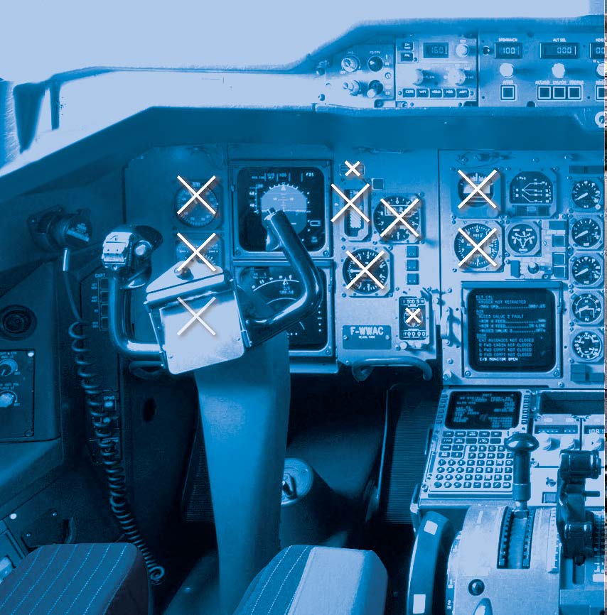
The A300-600 cockpit redesign serves to future-proof the UPS fleet for the remainder
of its life. A denser set of waypoints and routes in US airspace exceeded the capacity
of the current navigation database long ago. The need to operate in busier traffic led
the regulator to introduce new operational requirements, either mandates or quasi-
mandates such as FANS. Additionally, technology has opened up fresh possibilities,
such as new GPS-based approaches, on which more and more airports now rely.
The redesign provides an opportunity for safety enhancements. New functions and
upgraded hardware from the updated cockpit remove limitations and coping
operational strategies that the customer has to manage to fly the current A300-600.
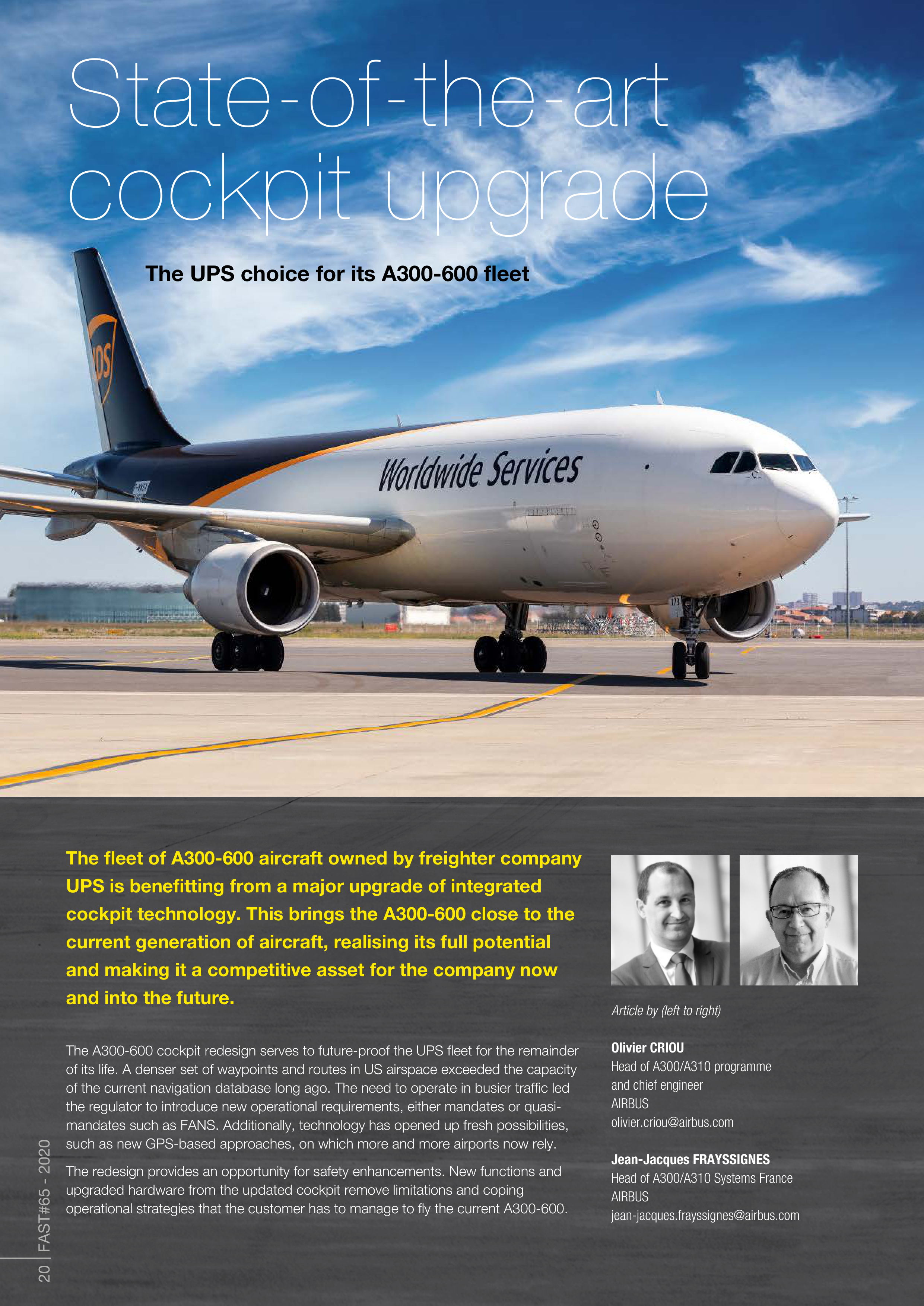
The UPS choice for its A300-600 fleet
The fleet of A300-600 aircraft owned by freighter company
UPS is benefitting from a major upgrade of integrated
cockpit technology. This brings the A300-600 close to the
current generation of aircraft, realising its full potential
and making it a competitive asset for the company now
and into the future.
Article by (left to right)
Olivier CRIOU
Head of A300/A310 programme
and chief engineer
AIRBUS
olivier.criou@airbus.com
Jean-Jacques FRAYSSIGNES
Head of A300/A310 Systems France
AIRBUS
jean-jacques.frayssignes@airbus.com


21 FAST#65 - 2020
State -of-the-art-cockpit-upgrade
Current fleet and decision to upgrade
UPS operates 52 A300-600s, and two simulators. From the point of view of counting
aircraft flight-cycles, this is a robust, young freighter fleet. The aircraft are flown two to
three times per day. Low utilisation combined with a robust design mean their
airframes have a long remaining structural life. UPS A300-600s are expected to fly for
the next 20 years.
The A300-600 was designed in the 1980s and entered into service in 1983. Airbus
ceased production of the aircraft in July 2007. Despite product evolutions brought into
this fleet over the years, there is still a significant gap compared to later aircraft designs
which have entered into service in recent years.
Until now UPS has been able to adapt in order to operate with these systems, but the
most effective way to optimise their current and future operations was to integrate a
comprehensive upgrade to the cockpit. UPS operates in the ‘next-day-delivery’ market
so modern cockpit functions bring a distinct advantage and are fundamental to a
business model which “sells a speed advantage”.
Despite being post-production, when approached by UPS in 2015 Airbus was
determined not to leave its customer without support. Stopping production of an
aircraft type does not mean the end of the programme. It is just a new phase where
Airbus remains engaged with customers, even for ambitious and challenging projects.
A holistic design and installation approach
- optimal for the customer
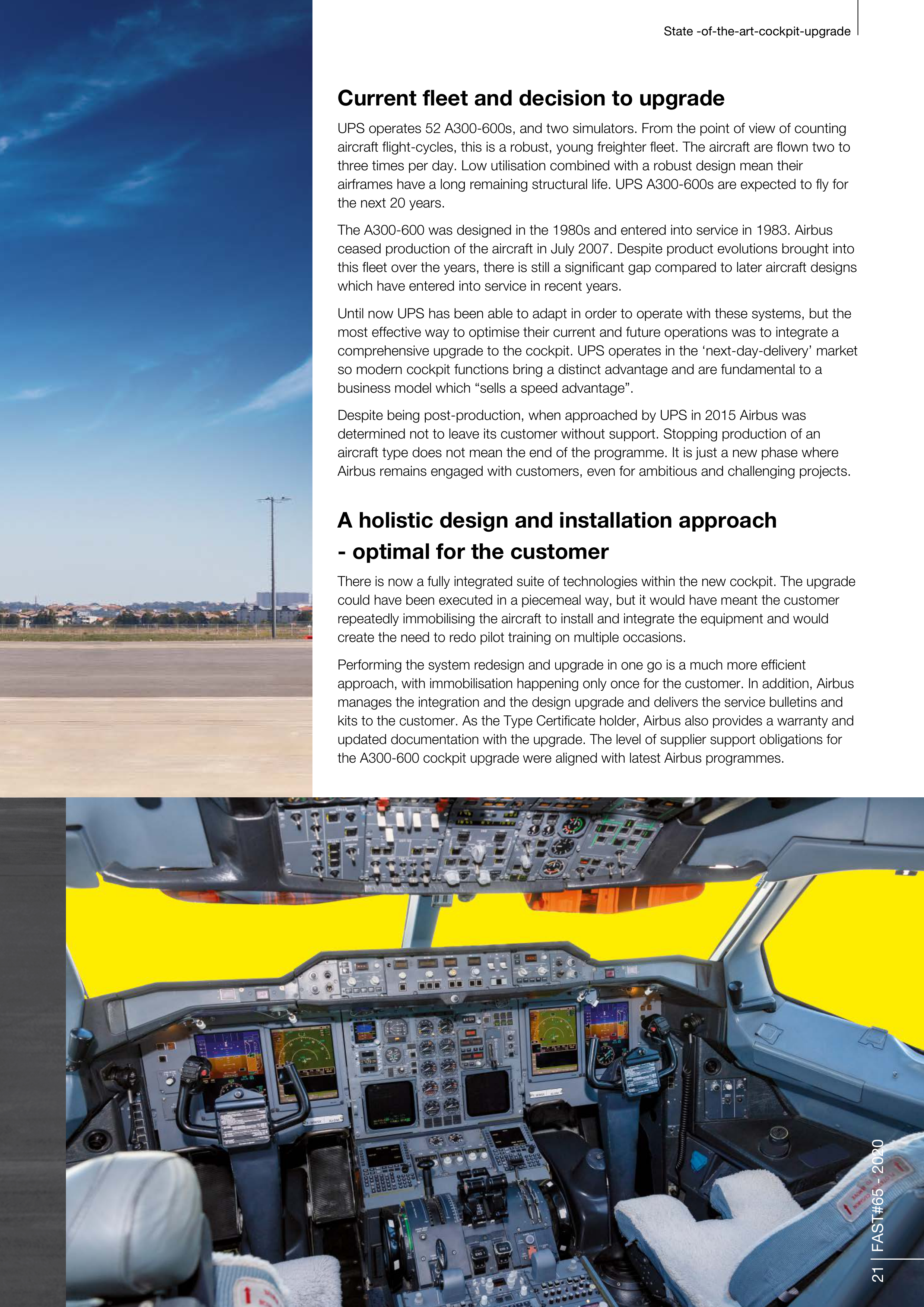
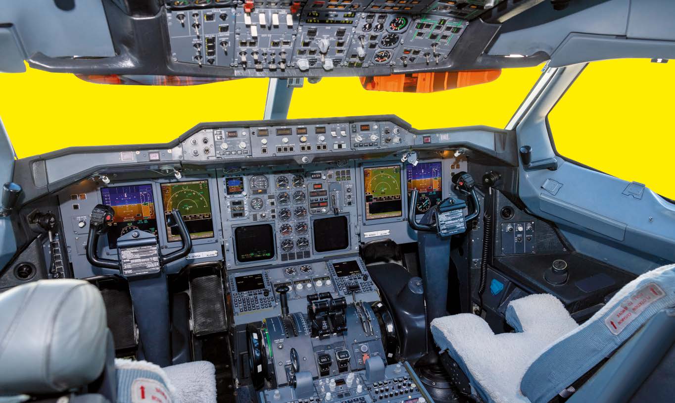
There is now a fully integrated suite of technologies within the new cockpit. The upgrade
could have been executed in a piecemeal way, but it would have meant the customer
repeatedly immobilising the aircraft to install and integrate the equipment and would
create the need to redo pilot training on multiple occasions.
Performing the system redesign and upgrade in one go is a much more efficient
approach, with immobilisation happening only once for the customer. In addition, Airbus
manages the integration and the design upgrade and delivers the service bulletins and
kits to the customer. As the Type Certificate holder, Airbus also provides a warranty and
updated documentation with the upgrade. The level of supplier support obligations for
the A300-600 cockpit upgrade were aligned with latest Airbus programmes.
State -of-the-art-cockpit-upgrade
22 FAST#65 - 2020
What new technology is on board?
Flight Management System
The FMS is a fundamental component
of modern avionics. The suite includes a
modern FMS which provides sophisticated
automation of in-flight tasks, primarily flight
plan management and navigation, but also
integration of all components of the auto-flight
system.
The new database has ample capacity to
carry all worldwide data required without
being full and is loadable in about ten minutes.
In addition, there is space for the 7% growth
observed every year, therefore covering the
remaining life of the UPS fleet.
This is a key enhancement as the original
database in the A300-600 was from the 1980s
and was then adequate to contain all options
and routes within its 1GB of Random Access
Memory (RAM). Compare this to the RAM of a
modern smartphone, which typically has 4GB
of RAM! But database growth over the years
means that even North America airspace
information alone vastly exceeds this memory
size. UPS therefore carves it up onto separate
regional databases with every database change
taking about 40 to 50 minutes per computer.
This is not compatible with the UPS business
need for efficiency and compromises
competitive advantage. This problem is now
fully resolved with the database embedded
in the new FMS.
There is also a new colour Multifunction Control
and Display Unit (MCDU). The MCDU is a
combination of a keyboard and a high-
performance Liquid-Crystal Display (LCD) that
allows pilots to input and modify flight plans.
New cockpit displays
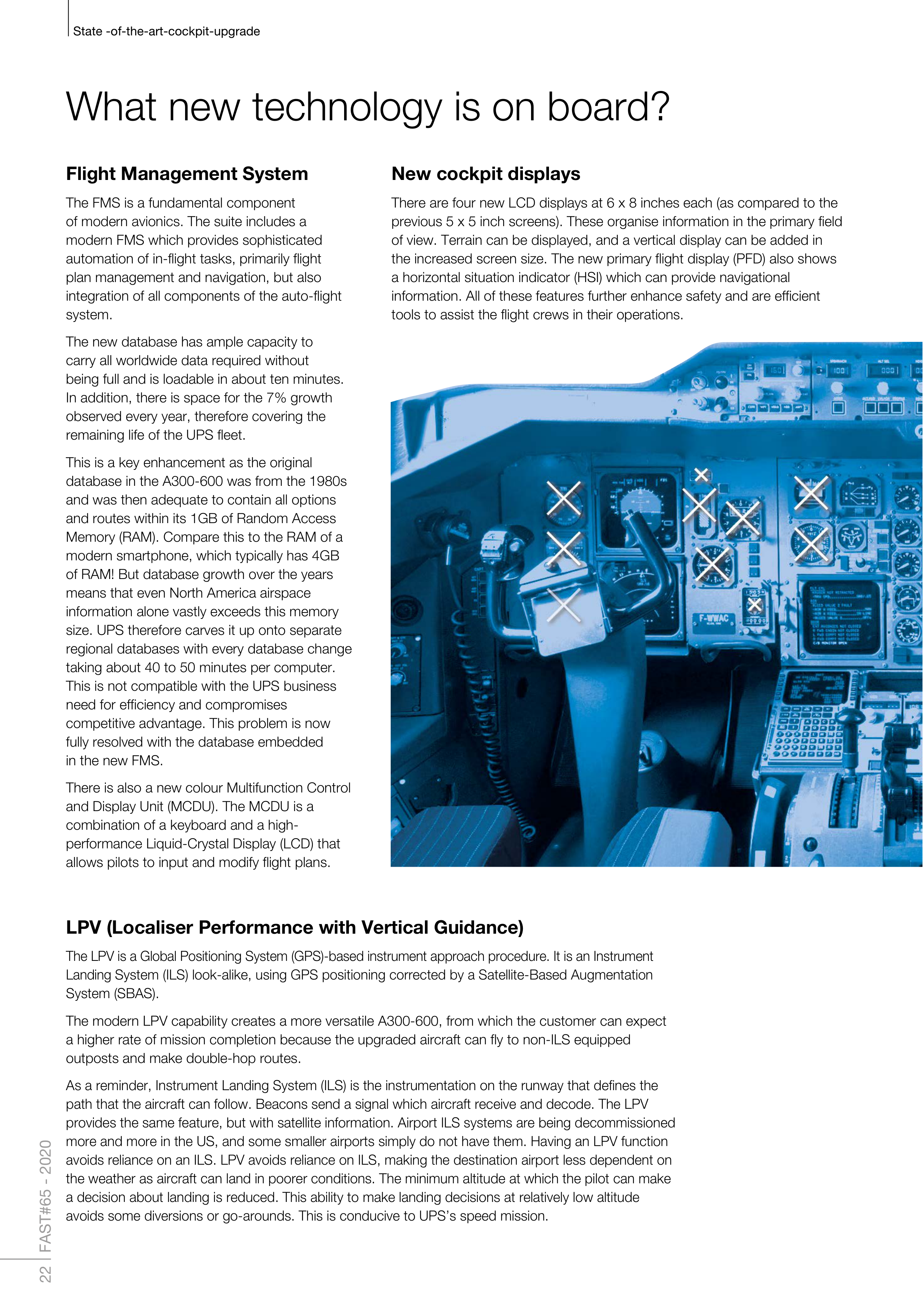
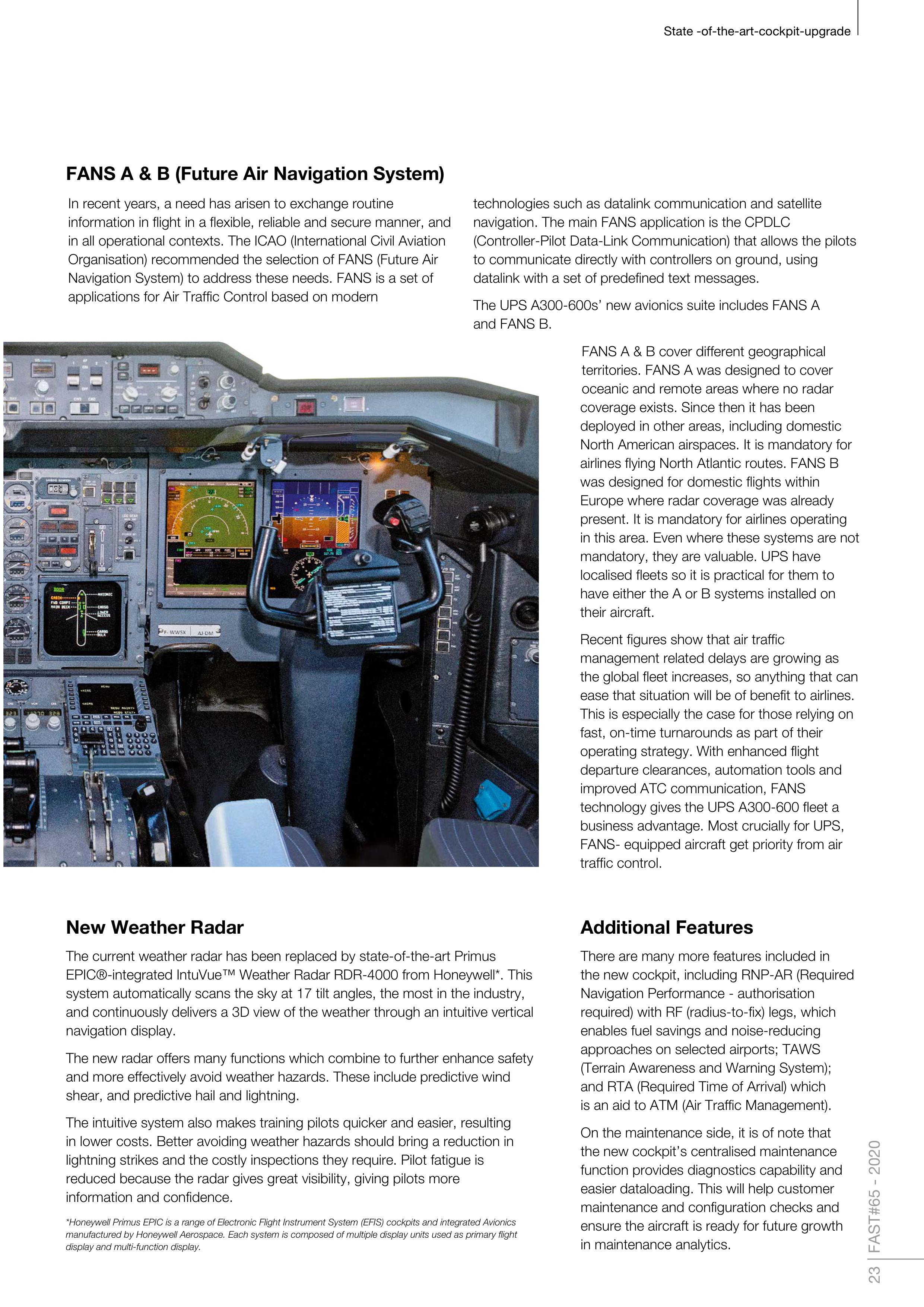
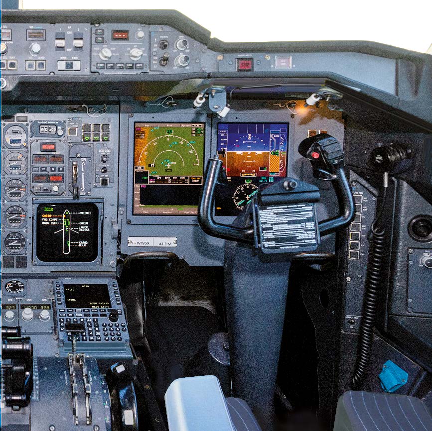
There are four new LCD displays at 6 x 8 inches each (as compared to the
previous 5 x 5 inch screens). These organise information in the primary field
of view. Terrain can be displayed, and a vertical display can be added in
the increased screen size. The new primary flight display (PFD) also shows
a horizontal situation indicator (HSI) which can provide navigational
information. All of these features further enhance safety and are efficient
tools to assist the flight crews in their operations.
LPV (Localiser Performance with Vertical Guidance)
The LPV is a Global Positioning System (GPS)-based instrument approach procedure. It is an Instrument
Landing
System (ILS) look-alike, using GPS positioning corrected by a Satellite-Based Augmentation
System (SBAS).
The modern LPV capability creates a more versatile A300-600, from which the customer can expect
a higher rate of mission completion because the upgraded aircraft can fly to non-ILS equipped
outposts and make double-hop routes.
As a reminder, Instrument Landing System (ILS) is the instrumentation on the runway that defines the
path that the aircraft can follow. Beacons send a signal which aircraft receive and decode. The LPV
provides the same feature, but with satellite information. Airport ILS systems are being decommissioned
more and more in the US, and some smaller airports simply do not have them. Having an LPV function
avoids reliance on an ILS. LPV avoids reliance on ILS, making the destination airport less dependent on
the weather as aircraft can
land in poorer conditions. The minimum altitude at which the pilot can make
a decision about landing is
reduced. This ability to make landing decisions at relatively low altitude
avoids some diversions or go-arounds.
This is conducive to UPS’s speed mission.
23 FAST#65 - 2020
State -of-the-art-cockpit-upgrade
In recent years, a need has arisen to exchange routine
information in flight in a flexible, reliable and secure manner, and
in all operational contexts. The ICAO (International Civil Aviation
Organisation) recommended the selection of FANS (Future Air
Navigation System) to address these needs. FANS is a set of
applications for Air Traffic Control based on modern
technologies such as datalink communication and satellite
navigation. The main FANS application is the CPDLC
(Controller-Pilot Data-Link Communication) that allows the pilots
to communicate directly with controllers on ground, using
datalink with a set of predefined text messages.
The UPS A300-600s’ new avionics suite includes FANS A
and FANS B.
FANS A & B cover different geographical
territories. FANS A was designed to cover
oceanic and remote areas where no radar
coverage exists. Since then it has been
deployed in other areas, including domestic
North American airspaces. It is mandatory for
airlines flying North Atlantic routes. FANS B
was designed for domestic flights within
Europe where radar coverage was already
present. It is mandatory for airlines operating
in this area. Even where these systems are not
mandatory, they are valuable. UPS have
localised fleets so it is practical for them to
have either the A or B systems installed on
their aircraft.
Recent figures show that air traffic
management related delays are growing as
the global fleet increases, so anything that can
ease that situation will be of benefit to airlines.
This is especially the case for those relying on
fast, on-time turnarounds as part of their
operating strategy. With enhanced flight
departure clearances, automation tools and
improved ATC communication, FANS
technology gives the UPS A300-600 fleet a
business advantage. Most crucially for UPS,
FANS- equipped aircraft get priority from air
traffic control.
FANS A & B (Future Air Navigation System)
New Weather Radar
The current weather radar has been replaced by state-of-the-art Primus
EPIC®-integrated IntuVue™ Weather Radar RDR-4000 from Honeywell*. This
system automatically scans the sky at 17 tilt angles, the most in the industry,
and continuously delivers a 3D view of the weather through an intuitive vertical
navigation display.
The new radar offers many functions which combine to further enhance safety
and more effectively avoid weather hazards. These include predictive wind
shear, and predictive hail and lightning.
The intuitive system also makes training pilots quicker and easier, resulting
in lower costs. Better avoiding weather hazards should bring a reduction in
lightning strikes and the costly inspections they require. Pilot fatigue is
reduced because the radar gives great visibility, giving pilots more
information and confidence.
*Honeywell Primus EPIC is a range of Electronic Flight Instrument System (EFIS) cockpits and integrated Avionics
manufactured by Honeywell Aerospace. Each system is composed of multiple display units used as primary flight
display and multi-function display.
Additional Features
There are many more features included in
the new cockpit, including RNP-AR (Required
Navigation Performance - authorisation
required) with RF (radius-to-fix) legs, which
enables fuel savings and noise-reducing
approaches on selected airports; TAWS
(Terrain Awareness and Warning System);
and RTA (Required Time of Arrival) which
is an aid to ATM (Air Traffic Management).
On the maintenance side, it is of note that
the new cockpit’s centralised maintenance
function provides diagnostics capability and
easier dataloading. This will help customer
maintenance and configuration checks and
ensure the aircraft is ready for future growth
in maintenance analytics.


24 FAST#65 - 2020
State -of-the-art-cockpit-upgrade
It will be no surprise that a complex and ambitious project such as this raised some
challenges. It requires a multi-functional team - including experts in upgrades,
engineering, testing, procurement, supply chain, production, quality, and support
- to collaborate and find solutions to suit the customer’s needs.
Although the A300-600 was originally designed by older tools, the team used
modern 3D techniques to conceive and check the installation of the
new systems into the existing fuselage nose.
As there were no A300-600 test aircraft at Airbus’ disposal, UPS
and Airbus agreed to lease one of UPS’ aircraft for flight testing.
Kevin O’HARA
, Director of Project Engineering/Aircraft Acquisitions for UPS
Airlines, told FAST that the primary reason to upgrade the A300-600 cockpit
was the navigation database capacity in the flight management system.
The navigation data required to fly in current national air systems has grown
significantly over the last five years. UPS estimates that it will continue to grow
in the future at a rate of approximately 7% per year as the United States
manages increased air traffic and congestion in the national airspace and
terminal areas.
Navigational database growth can be attributed to the move from fixed
navigation aids such as a very high-frequency (VHF) omnidirectional range
(VOR) system to coordinates in space to support required navigational
performance (RNP).
The new technology will significantly reduce the requirement to upload new
navigation data from once per aircraft per day to the typical monthly update.
The time required for multiple data loads are a significant burden on the UPS
operation resulting in aircraft routing constraints, and the potential for
dispatch delays and interrupted service to our customers.
The associated benefits to UPS from the new suite of integrated cockpit
technology includes reduced maintenance cost, a substantial improvement
in systems/component reliability, and safety improvements. There is also
the ability to operate efficiently in both highly congested airspace as well
as smaller airports during poor weather operations.
This cockpit upgrade was required to enable UPS to operate the aircraft
efficiently into the future. The A300-600 was first introduced to UPS in 2000.
The average fleet age today is 16 years. The cockpit upgrade extends that life
expectancy by a further 20 years.
Continued use of our fleet would certainly not be realistic if the technology
didn’t support the demands of our business operation, government
regulations, part obsolescence, and the service levels required for
our customers.
What is it like to fly?
Airbus test pilot,
Captain Michel BONNIFET
,
commented after his first flight
in the new cockpit:
I really know this
aircraft well and the
upgrade felt like a
generational change.
It is now like flying
a modern airliner
Overcoming technical challenges
“
“
”
”
Customer motivation:
Why upgrade the cockpit?

State -of-the-art-cockpit-upgrade
The cockpit technology upgrade gives UPS a go-anywhere fleet of
A300-600 aircraft, with high-tech, flexibility and reliability supporting their
mission to deliver speed to their customers.
It provides UPS with an original equipment manufacturer (OEM) solution,
and an easier way to operate in an ever more demanding business world.
C O N C L U S I O N
Get the FAST app
Scan the QR code or search
‘Airbus FAST’ on your app store
25 FAST#65 - 2020
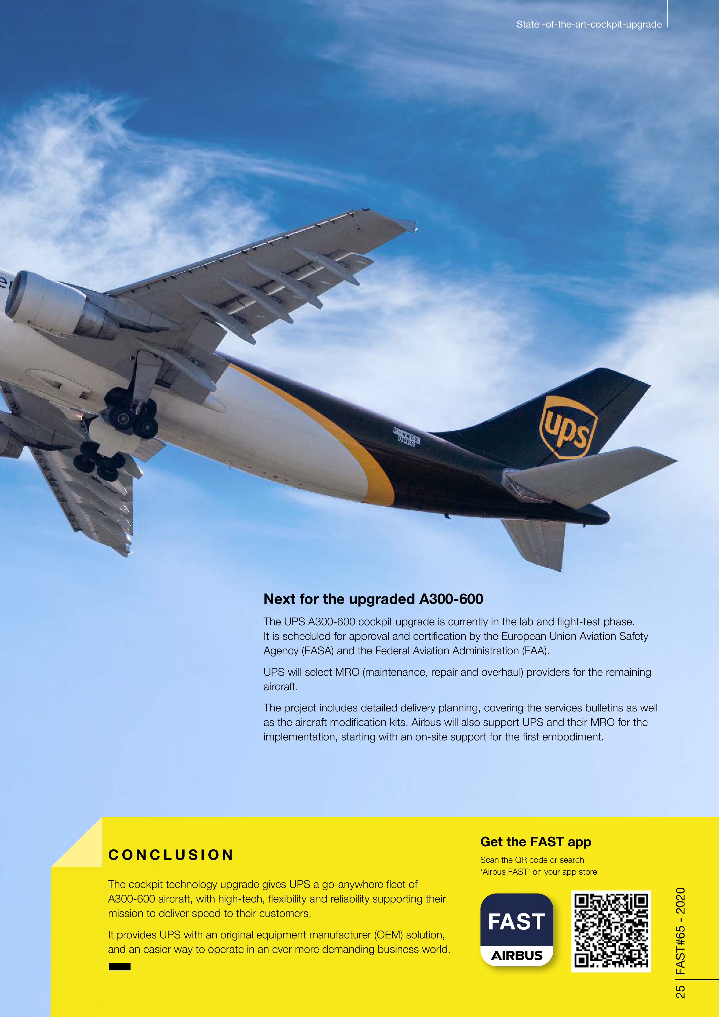
Next for the upgraded A300-600
The UPS A300-600 cockpit upgrade is currently in the lab and flight-test phase.
It is scheduled for approval and certification by the European Union Aviation Safety
Agency (EASA) and the Federal Aviation Administration (FAA).
UPS will select MRO (maintenance, repair and overhaul) providers for the remaining
aircraft.
The project includes detailed delivery planning, covering the services bulletins as well
as the aircraft modification kits. Airbus will also support UPS and their MRO for the
implementation, starting with an on-site support for the first embodiment.
26 FAST#65 - 2020
Protecting precious
assets
Parking and storing aircraft
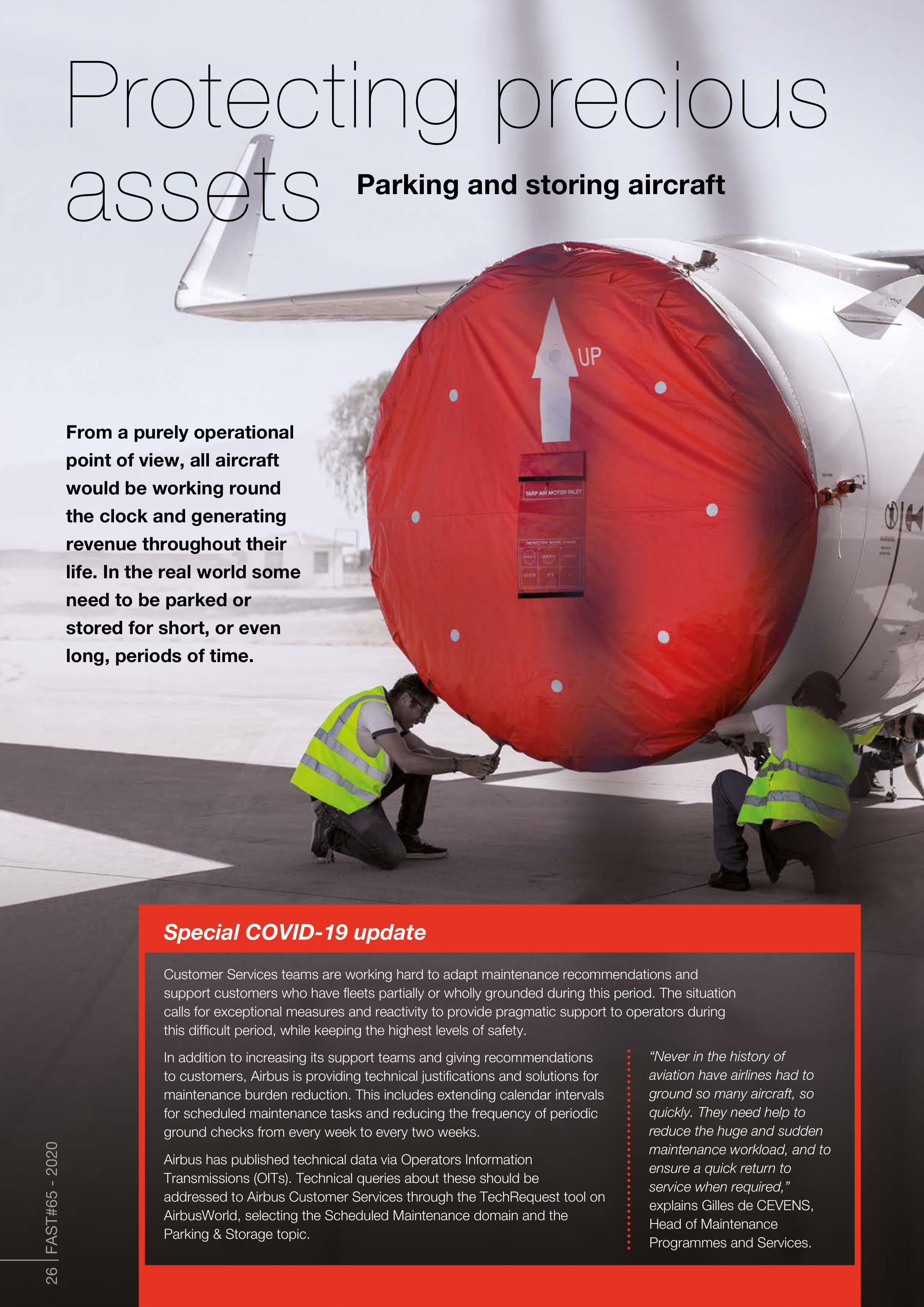
From a purely operational
point of view, all aircraft
would be working round
the clock and generating
revenue throughout their
life. In the real world some
need to be parked or
stored for short, or even
long, periods of time.
Special COVID-19 update
Customer Services teams are working hard to adapt maintenance recommendations and
support customers who have fleets partially or wholly grounded during this period. The situation
calls for exceptional measures and reactivity to provide pragmatic support to operators during
this difficult period, while keeping the highest levels of safety.
In addition to increasing its support teams and giving recommendations
to customers, Airbus is providing technical justifications and solutions for
maintenance burden reduction. This includes extending calendar intervals
for scheduled maintenance tasks and reducing the frequency of periodic
ground checks from every week to every two weeks.
Airbus has published technical data via Operators Information
Transmissions (OITs). Technical queries about these should be
addressed to Airbus Customer Services through the TechRequest tool on
AirbusWorld, selecting the Scheduled Maintenance domain and the
Parking & Storage topic.
“Never in the history of
aviation have airlines had to
ground so many aircraft, so
quickly. They need help to
reduce the huge and sudden
maintenance workload, and to
ensure a quick return to
service when required,”
explains Gilles de CEVENS,
Head of Maintenance
Programmes and Services.


27 FAST#65 - 2020
Article by
Why store an aircraft that could be earning?
Aircraft are sometimes referred to as ‘revenue generators’. It is common for them to
enter commercial service within days of delivery to operators and a key aim of fleet
planning is to safely maximise the time each aircraft spends in the air carrying
passengers or freight. Parking or storing an aircraft is an expensive option but there
are sometimes compelling reasons to do so.
Time away from operations, such as when waiting for maintenance activities, isn’t
unusual and some operators have business models which include being less busy
at particular times of year. Offering holiday-related travel to regions where a seasonal
climate is part of the destinations’ appeal might mean anticipating a regular ‘down-
season’. Reducing flight frequency or closing some routes and then parking or storing
part of the fleet makes better financial sense than flying aircraft with too many empty
seats. Aircraft are also sometimes taken out of service while awaiting return to the
leasing company that owns them. Getting all the relevant dates and activities involved
to coincide perfectly can be difficult so a short period of parking can be a practical
solution.
However, unplanned events can also create a need for parking or storage, usually
in circumstances where the operator has little choice but still needs to protect their
asset. These can range from technical issues which can’t be resolved quickly to an
aircraft being grounded by the authorities while a long way from its base. Financial
issues can also create a need for storage, such as bankruptcy, outstanding fuel bills,
lack of ground and cabin staff or pilots, and abandonment of aircraft owned by
lessors.
Regional or global crises can lead to a complete or partial collapse in the usual
infrastructure needed to support aviation. Humanitarian disasters, widespread health
or sanitary problems, extreme economic or political events; whatever the reason,
parking or storage might be the only viable option available to aircraft operators
caught in the middle of such events.
Why protection is key
Once an aircraft is out of service the likelihood of issues caused by the wear and
tear of routine flying is reduced. Nevertheless, without proper protection a host of
new threats to the condition of the aircraft can emerge depending on the climate
and conditions the aircraft is stored in. Weather can cause problems. If rain,
snow, salty air, dust or sand enter air ducts, they can degrade or contaminate
the mechanical parts they come into contact with. Extremely high winds can also
cause damage to an aircraft that might be considered safe and stable in normal
circumstances. High humidity, lightning strikes and volcanic ash also require
special consideration.
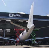
Protection against unwelcome ‘passengers’ is also vital. It only takes weeks for
rodents, birds and insects to cause serious damage to a previously pristine cabin
with seats, carpets and wiring all vulnerable particularly if a nest is established.
Returning to service without an expensive and time-consuming deep-clean and
repair operation is unthinkable. In extreme cases, infestation can also lead to
blocked ducts, some of which could have safety repercussions – again thorough
checks and remedial actions take time so avoiding the problem is the best solution.
Protecting precious assets
Parking and storage - what’s the difference?
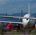
‘Parking’
usually means the aircraft is taken out of
operation for up to six months. Sometimes longer spells
of parking mean coming out of a flight-ready condition,
but it is more usual to carry out the regular light
maintenance needed to preserve a ‘ready to go’ state
which allows a rapid return to service. Every week over
100 aircraft are parked for periods which exceed 14 days.
‘Storage’
generally applies when a rapid or unexpected
return to service is unlikely and the planned period out of
service is up to two years. In these cases airworthiness can
be maintained but more preferable is a reduced maintenance
schedule combined with preservation activities, such as
sealing and greasing.
Christoph MAIER
Customer Manager
Customer Services Engineering
AIRBUS
christoph.maier@airbus.com
Christian NIEDERST
Field Service Representative
Customer Services
AIRBUS
christian.niederst@airbus.com
28 FAST#65 - 2020
Protecting precious assets
Help! - Requests from around the world
A wide variety of natural phenomena can threaten stored or parked aircraft.
Customer Services teams are often asked for advice on dealing with potential
issues, some of which have a distinct regional flavour.
Middle East:
With up to 80 million locusts
in the central area of a swarm the need for
extra caution is clear. Moving aircraft into
hangars and sealing ducts and potential
entry points is crucial.
Japan:
AMM (Aircraft Maintenance
Manual) procedures cover mooring
of aircraft in winds up to 75 knots.
Severe typhoons have winds of at
least 80 knots while super typhoons
are defined by winds of at least 100
knots. Advice varies according to
specific circumstances but it can
include moving aircraft into hangars
- or out of them if the buildings
themselves are at risk. Filling fuel
tanks can add extra weight to the
aircraft while removing plastic
sheeting prevents it from catching
the wind and becoming a ‘sail’ which
drags the aircraft.
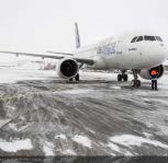
Siberia:
In winter, temperatures can reach below
40°C. In ‘deep freeze’ cold of this nature, some
plastic and rubber derived parts can become
brittle so care is needed.
Asia and Northern Europe:
Heavy rain and high
humidity can cause mildew inside the aircraft. Without
careful sealing, extreme water levels can even cause
cabin flooding leading to litres of water pouring out at
the end of the storage period. However, sealing must
be done correctly to ensure that evaporation is still
possible, thus preventing mould.
Caribbean:
Salty and humid
conditions require
extra protection.
Overall it is fair to say that, depending on location and on seasonal and
operational conditions, the exact procedures for storage or parking vary.
However, protecting the aircraft against contamination, mechanical degradation
or damage is always essential.
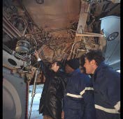
Aircraft should be parked or stored in clean and serviceable condition. Measures
should be taken to clean the cabin, galleys and cargo, service all the systems,
protect the exposed areas, and carry out the periodical checks. Anticipation is
also vital. Use experience and knowledge of the environment as a guide, to take
appropriate actions for cold weather, ventilation, mooring, and ensuring that
sufficient fuel is in the tanks for water draining or APU (auxiliary power unit)
operation and engine runs.
AMM or Maintenance Procedure tasks exist to prepare an aircraft for parking/
storage and return it to service and these should always be followed.
Fumigation
Avionics bay
contamination
Sun screens
Fungus
Fuel
contamination
De-calcification
Sterilisation
Monitor
Maintain
Clean
Service
29 FAST#65 - 2020
Protecting precious assets
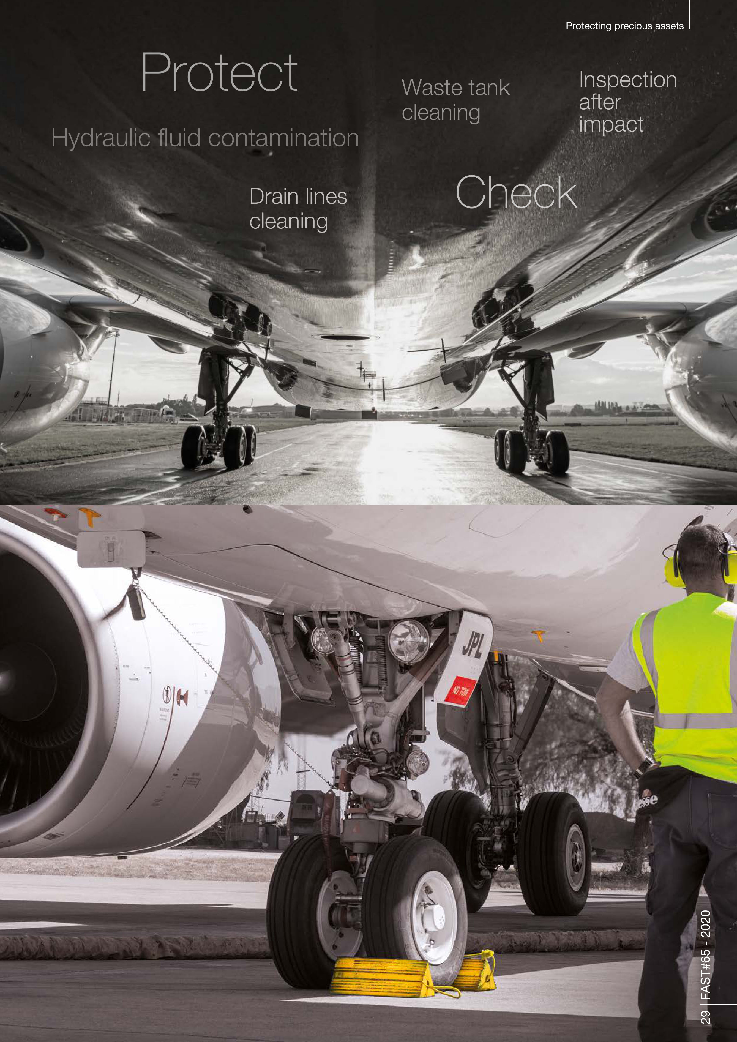
Protect
Hydraulic fluid contamination
Inspection
after
impact
Drain lines
cleaning
Waste tank
cleaning
Check
30 FAST#65 - 2020
Protecting precious assets
Asking the right questions
When deciding whether to park or store an aircraft, you should check requirements carefully.
An out-of-operation aircraft can be maintained with an approved maintenance programme.
Consult the AMM to find procedures and check which are mandatory.
Seven frequently asked questions:
Is it necessary to park or store an aircraft before a scheduled maintenance check,
working party or cabin refurbishing?
Check the guidelines regarding your specific circumstances.
What can I do when the parking or storage period has expired?
Normally after two years an aircraft must return to operation before going back into storage.
This should become a deviation in the future and there will be no need to re-fly if the aircraft
is not required by the operator.
Is it possible to remove parts from an aircraft that is parked or stored?
Parked aircraft should be flight ready – batteries can be removed to preserve them as they
can be quickly reinstalled. Other items can be removed in specific conditions, for example
some of the fire extinguishers in the cabin aren’t necessary for a flight without passengers.
However, removing parts for parking is highly restricted.
In stored aircraft, it is more common for major components to be removed. Engines, APUs,
flaps and computers all have high value and can be transferred to in-service aircraft.
The best solutions often depend on the planned storage time. Operators have some flexibility
and should check with Airbus if in doubt. It can become a costly process if an aircraft needs
to return to service when major parts have been removed, so operators should be clear about
the storage mode and duration before making decisions.
What is the starting date to be used to calculate future ground checks?
All dates must be calculated based on the last flight date. This rule applies even if an aircraft is
initially parked then moves to storage, or if it needs two months of maintenance then is parked.
How does a parking or storage period influence the scheduled maintenance?
Scheduled or planned maintenance must still be done, but may be postponed until the end
of a parking/storage period if operators have agreement from their local authority.
If an aircraft is in short-term parking mode, it is advisable to do scheduled maintenance
when due, to avoid delays on return-to-service.
Who shall I ask questions to related to engines and APU?
Operators need to refer directly to the engine and APU manufacturers in line with legal
requirements.
How can Airbus support me regarding aircraft parking and storage?
Operators can log a request in the Airbus TechRequest too, for advice, deviation options,
and overdue maintenance where aircraft needs to be flown to a specific maintenance base
or to new owner.
Operators who supply full and accurate information to Airbus can be supported with
documents confirming that procedures have been followed – these can be a requirement
for airworthiness authorities.
ISI 10.00.00003
Guidelines
for appropriate
actions
ISI 10.00.00004
Parking or Storage
extension
ISI 10.00.00005
Aircraft system
integrity
ISI 10.00.00006
Scheduled
maintenance
control
ISI 10.00.00007
Tasks calendar
ISI 10.00.00008
Engines & APU
on wing
ISI 10.00.00009
Assistance and ISI
10.00.00010 cover
deviations
1)
2)
3)
4)
5)
6)
7)


Whatever the circumstances, when parking or storage is the right
solution for an aircraft it is wise to prepare in advance and strongly
advisable to refer to the latest recommendations and guidelines in
the AMM, in-service information and technical follow-up documents.
Making full use of Airbus support as early as possible to evaluate
specific needs, avoid unplanned deviations and anticipate costs will
also help. Keeping delays and costs down means thinking through
storage rental but also planning maintenance to avoid overdue work
causing a backlog which ultimately delays return-to-service.
The most crucial piece of advice is to get in touch early. This helps
all parties and allows the best possible experience of a potentially
complicated situation. Poorly planned and handled storage or parking
can lead to aircraft being prevented from returning to operation when
required and the consequences for revenues can be serious.
C O N C L U S I O N
Get the FAST app
Scan the QR code
or search ‘Airbus FAST’
on your preferred store
31 FAST#65 - 2020
Protecting precious assets
Back to service
To return an aircraft to service all the required maintenance must be carried out.
This includes all scheduled maintenance, daily and weekly servicing when needed,
and the restoration of any defects which may have arisen during the period of
storage or parking. Everything required to bring the aircraft back to operational
standards and ensure safe use is essential. Calendar items as well as mandatory
items, Airworthiness Directives, All Operator Telex, shelf-life equipment, and
inspections due must be included. Upon release into service the aircraft must be
fully airworthy in every respect.
Support and responsibilities
Airbus deals with several requests for support every day and offers advice as well
services. It can evaluate specific situations to help ensure the safety and serviceability
required for an easy return-to-service. Operators are responsible for ensuring correct
and complete information for Airbus when preparing validation from their authorities.
As for any maintenance actions, parking and storage have to be approached like a
planned maintenance check. All the regulations and standard practices apply.
Preparation, traceability and proper execution of the maintenance tasks are essential
for a safe and uncomplicated release back into service.
Keeping the AMM current
By reporting back to Airbus, operators can help keep the AMM up-to-date in the light
of experience and evolving techniques. This happened, for example, when operators
explained that the aluminium covers being used to prevent fabric fading inside the
cabin were actually causing paint discoloration around the windows. A new technique
was then developed to resolve this issue.
Scheduled Maintenance seminars
These include some information on critical situations for parking and storing, aircraft
waiting for dismantling, or needing leasing company acceptance for flight, aircraft on
standby and more
- sched-maint.seminar@airbus.com

FAST
FORWARD
Airbus is powered by innovation to redefine and shape the future of flight
Birds of a feather flock together
When a flock of geese takes to the skies, it usually adopts a V-shape. But why?
The answer lies in a flight technique known as “wake-energy retrieval.” When a bird flaps
its wings, air flows over the wings and swirls upwards behind the wingtips.
This flow creates a wake through which air gets pushed upward. When another bird
enters this upwash, it immediately benefits from free lift. Just like birds, every
aircraft creates a wake while flying. Flying together could thus help aircraft to
retrieve the lost kinetic energy by positioning a follower aircraft in the air
upwash of one of the lead aircraft’s wakes.
Today, Airbus is exploring the benefits of wake-energy retrieval for
commercial aircraft through the flight demonstrator project fello’fly.
If the technology behind fello’fly proves viable, this collaborative
activity could produce fuel savings of between 5-10% per trip.
“It’s a great opportunity for our industry to demonstrate a joint
commitment to reducing our use of fossil fuels,”
said Nick
Macdonald, fello’fly Demonstrator Leader, Airbus.
Airbus aims to involve manufacturers, airlines, air navigation
service providers, regulators and authorities to help the
aviation industry to reduce fuel consumption and CO
2
emissions. The next flight tests are expected to take
place in 2020.
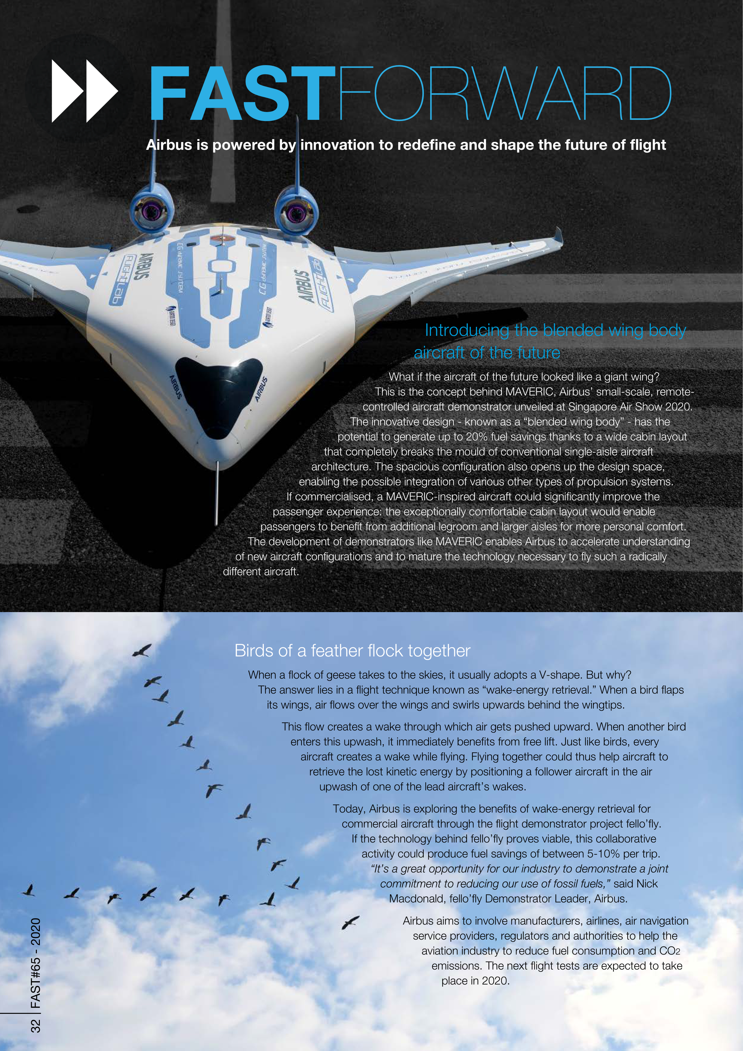
Introducing the blended wing body
aircraft of the future
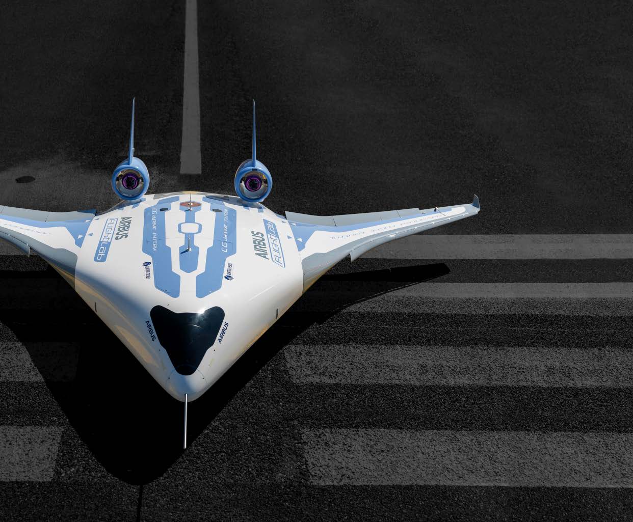
What if the aircraft of the future looked like a giant wing?
This is the concept behind MAVERIC, Airbus’ small-scale, remote-
controlled aircraft demonstrator unveiled at Singapore Air Show 2020.
The innovative design - known as a “blended wing body” - has the
potential to generate up to 20% fuel savings thanks to a wide cabin layout
that completely breaks the mould of conventional single-aisle aircraft
architecture. The spacious configuration also opens up the design space,
enabling the possible integration of various other types of propulsion systems.
If commercialised, a MAVERIC-inspired aircraft could significantly improve the
passenger experience: the exceptionally comfortable cabin layout would enable
passengers to benefit from additional legroom and larger aisles for more personal comfort.
The development of demonstrators like MAVERIC enables Airbus to accelerate understanding
of new aircraft configurations and to mature the technology necessary to fly such a radically
different aircraft.
32 FAST#65 - 2020

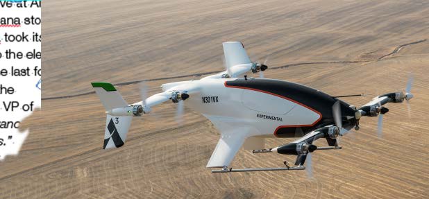
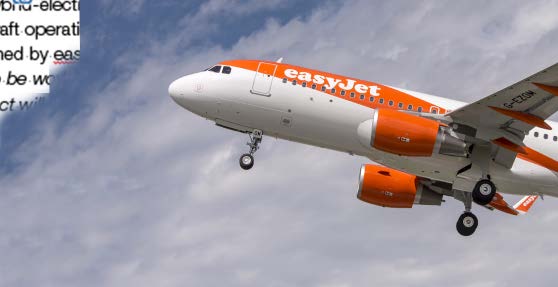

Connecting Chinese airlines to the Skywise data platform
Airbus is teaming up with Alibaba Cloud, the data intelligence backbone
of Alibaba Group, to co-develop a Skywise Data Centre in China.
By partnering with Alibaba Cloud and utilising the local data centre,
Skywise will provide customised services for Chinese domestic
airlines, as well as features and tools for data compliance
required for Chinese airlines to join the platform.
Since the beginning of 2019, Airbus has rolled out
advanced analytics services to Chinese domestic airlines
through Skywise. To date, Spring Airlines, Yunnan
Hongtu Airlines and Zhejiang Loong Airlines have
connected to Skywise. Approximately 1,800 Airbus
aircraft are operated by Chinese airlines today.
Paving the way for safe integration of drones into airspace
Commercial drone remote pilots will soon be able to benefit from a safer, faster and more seamless
experience when planning, reviewing and conducting their flights thanks to a new collaboration between
Airbus UTM (Unmanned Traffic Management) and DroneDeploy, the largest drone software platform
in the US. Airbus UTM has integrated its UTM software into DroneDeploy’s drone management
platform to offer airspace authorisation and flight briefings for commercial drone remote pilots.
One of the key benefits of the integration is the speed at which DroneDeploy remote pilots will
be able to secure digital flight authorisation and a guaranteed level of safety.
“Our integration
with DroneDeploy streamlines the flight authorisation process for DroneDeploy commercial
pilots, while laying the foundation for new services and safe cooperation of drones in
airspace,”
said Joe Polastre, Head of UTM Products, Airbus. The integration is already
being tested in private beta with DroneDeploy’s enterprise customers, and a full
release is expected to arrive in 2020.
easyJet & Airbus take important next step to help decarbonise the aviation industry
What are the requirements necessary for the large-scale introduction of hybrid-electric aircraft?
What infrastructure will be required? How will day-to-day commercial aircraft operations be
impacted? These questions are at the heart of a joint research project signed by easyJet
and Airbus. According to Johan Lundgren, easyJet CEO:
“I’m delighted to be working
with Airbus on a new hybrid-electric plane research partnership. The project will aim to
identify the detailed technical challenges and requirements for electric and hybrid-
electric planes when deployed for short-haul flying around Europe so that we can
help shape the technology and airline networks of the future. We hope this will
be an important step towards making hybrid-electric planes a reality.”
The announcement comes several months after Airbus signed a similar agree
-
ment with SAS Scandinavian Airlines to study infrastructure development
and commercial operations needs for hybrid-electric aircraft.
The end of an era: Vahana takes its final test flight
The flagship programme that launched the urban air mobility initiative at Airbus has
now come to a close. In November 2019, the final page of the Vahana story was
written at the Pendleton UAS range in Oregon, USA. Here, Vahana took its final
test flight to the cheers of all those who have closely contributed to the electric
vertical take-off and landing vehicle (eVTOL)’s development over the last four
years. The Vahana programme was launched in 2016 at Acubed, the
company’s innovation centre in Silicon Valley. Says Zach Lovering, VP of
UAM Systems, Airbus:
“Learnings from Vahana will be used to advance
our relationship with regulators and to understand key technologies.”
Now that the Vahana programme has been completed, the project
team is looking forward to applying the lessons learned to the
future urban air vehicle at Airbus.
33
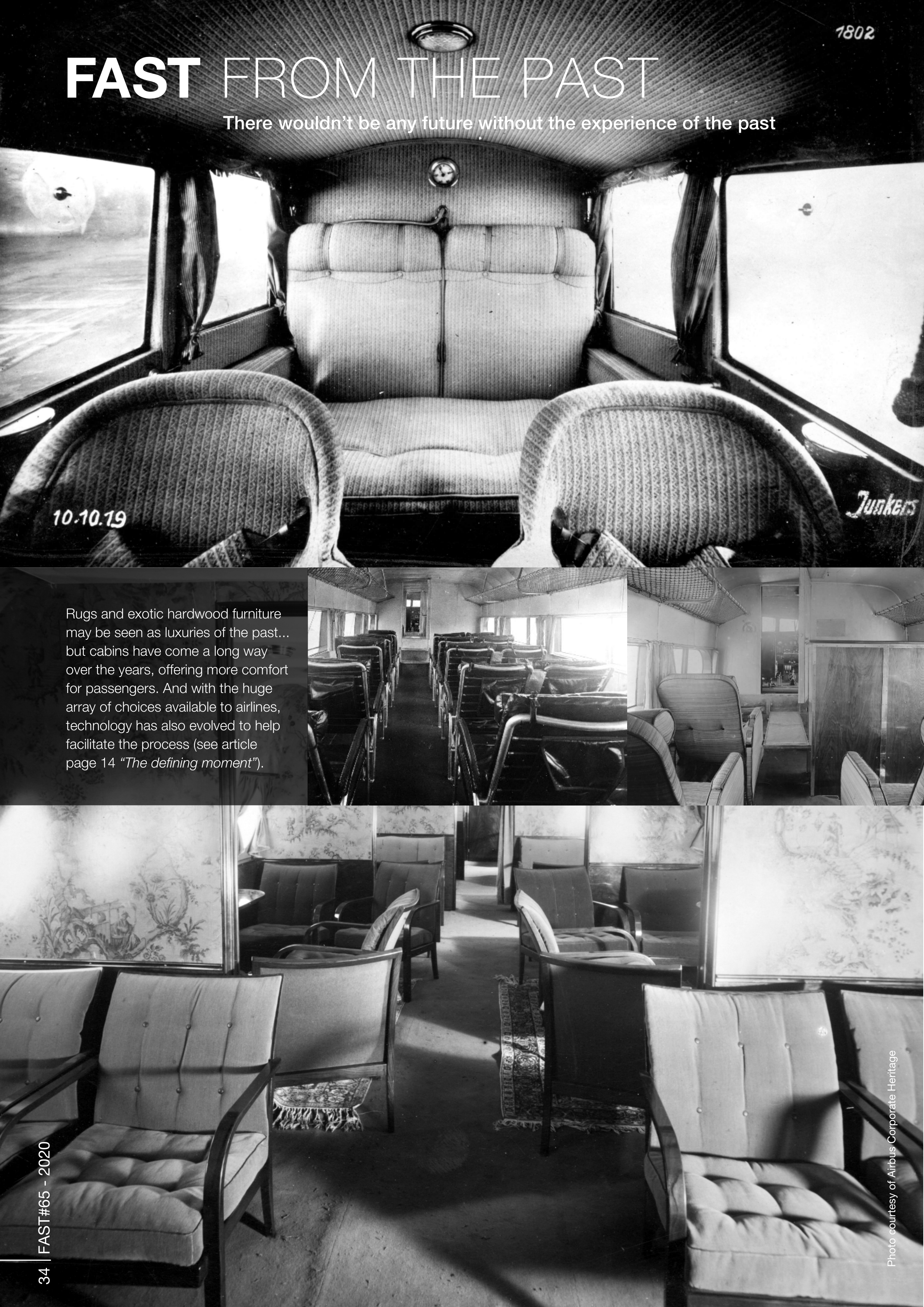
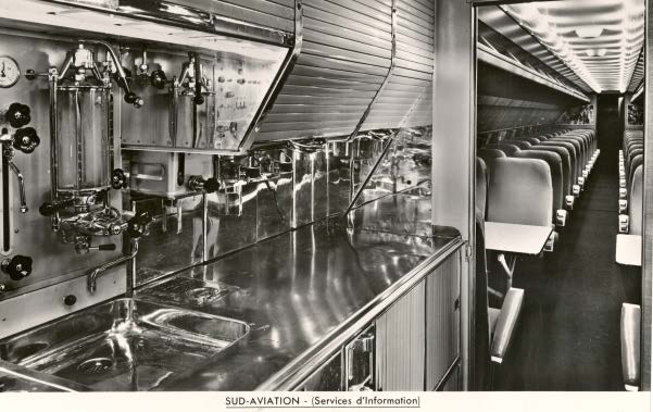
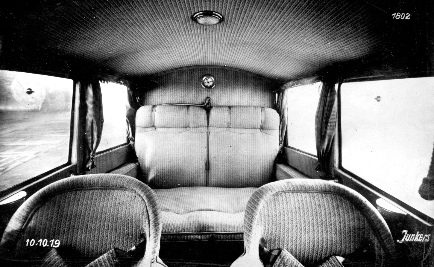
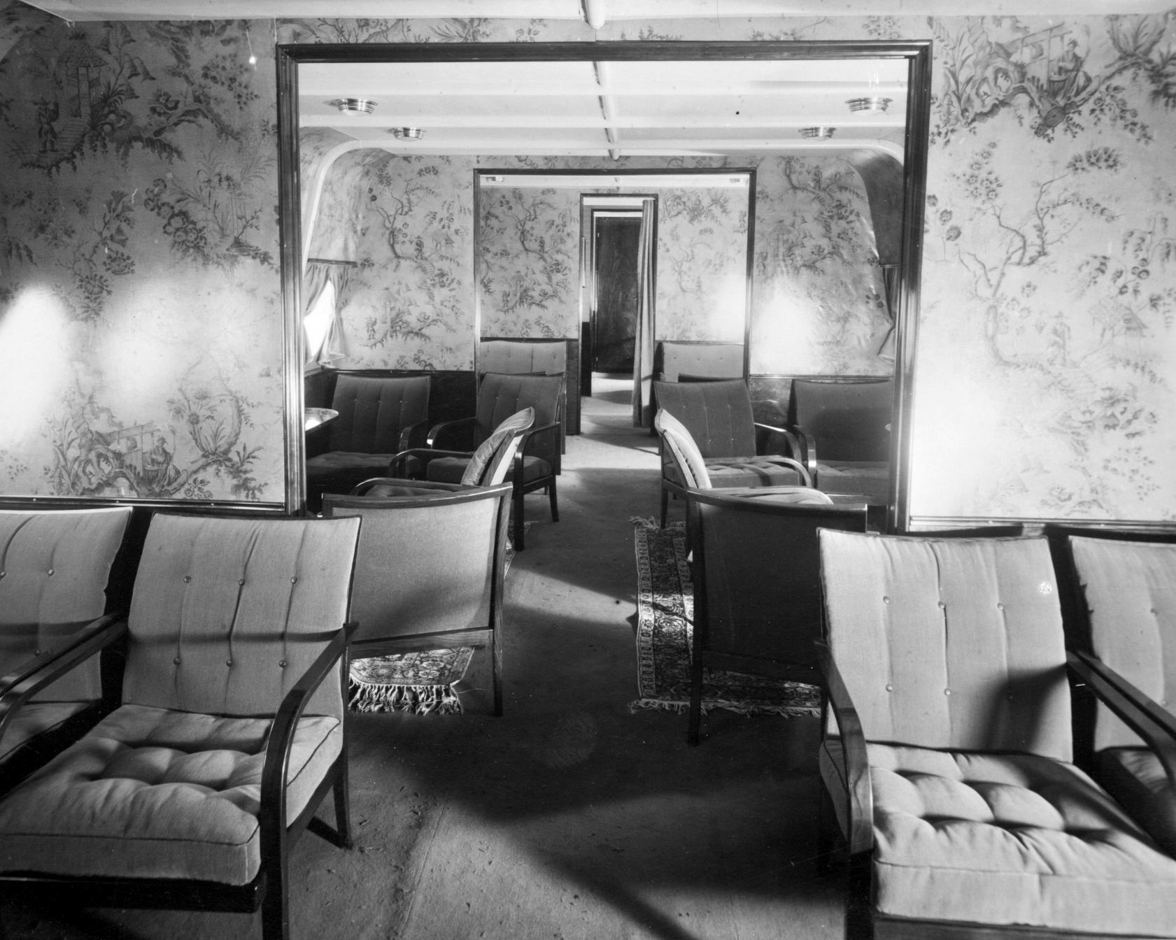

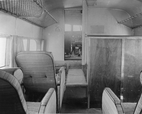
Photo courtesy of Airbus Corporate Heritage
There wouldn’t be any future without the experience of the past
FAST
FROM THE PAST
34 FAST#65 - 2020
Rugs and exotic hardwood furniture
may be seen as luxuries of the past...
but cabins have come a long way
over the years, offering more comfort
for passengers. And with the huge
array of choices available to airlines,
technology has also evolved to help
facilitate the process (see article
page 14
“The defining moment”
).
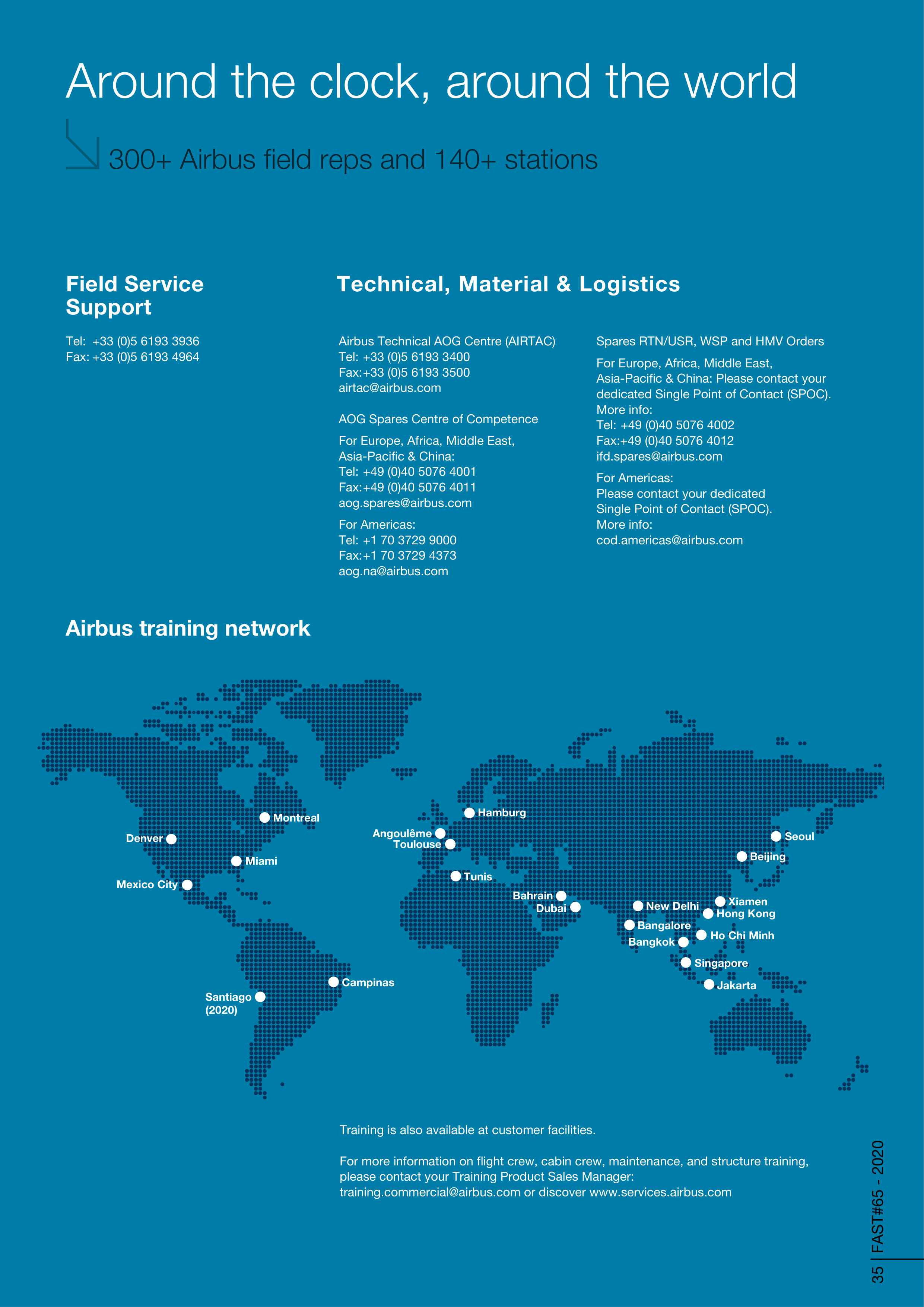

Around the clock, around the world
300+ Airbus field reps and 140+ stations
Technical, Material & Logistics
35 FAST#65 - 2020
Field Service
Support
Tel: +33 (0)5 6193 3936
Fax: +33 (0)5 6193 4964
Airbus Technical AOG Centre (AIRTAC)
Tel: +33 (0)5 6193 3400
Fax: +33 (0)5 6193 3500
airtac@airbus.com
AOG Spares Centre of Competence
For Europe, Africa, Middle East,
Asia-Pacific & China:
Tel: +49 (0)40 5076 4001
Fax: +49 (0)40 5076 4011
aog.spares@airbus.com
For Americas:
Tel: +1 70 3729 9000
Fax: +1 70 3729 4373
aog.na@airbus.com
Training is also available at customer facilities.
For more information on flight crew, cabin crew, maintenance, and structure training,
please contact your Training Product Sales Manager:
training.commercial@airbus.com or discover www.services.airbus.com
Spares RTN/USR, WSP and HMV Orders
For Europe, Africa, Middle East,
Asia-Pacific & China: Please contact your
dedicated Single Point of Contact (SPOC).
More info:
Tel: +49 (0)40 5076 4002
Fax:+49 (0)40 5076 4012
ifd.spares@airbus.com
For Americas:
Please contact your dedicated
Single Point of Contact (SPOC).
More info:
cod.americas@airbus.com
Airbus training network
Miami
Montreal
Toulouse
Beijing
Campinas
Singapore
New Delhi
Mexico City
Jakarta
Ho Chi Minh
Tunis
Bangkok
Hong Kong
Bangalore
Dubai
Hamburg
Denver
Seoul
Santiago
(2020)
Bahrain
Angoulême
Xiamen


WE’VE BUILT IT.
Designed with a digital future in mind,
the A350-1000 is the most modern
widebody aircraft in service today. And
will be for decades to come. Based on
a clean-sheet design and integrating
latest cutting-edge technologies, the
A350-1000 efficiently flies over 400
passengers in the quietest and most
comfortable cabin, all with 25% lower
fuel burn and CO
2
emissions. Making
the A350-1000 not only the smart
choice – but the responsible choice too.
The A350-1000. The future is here.
Ground-breaking. We make it fly.
FLY